HP G62-325CA Service Guide
HP G62-325CA Manual
 |
View all HP G62-325CA manuals
Add to My Manuals
Save this manual to your list of manuals |
HP G62-325CA manual content summary:
- HP G62-325CA | Service Guide - Page 1
PC and HP G62 Notebook PC Maintenance and Service Guide SUMMARY This guide is a troubleshooting reference used for maintaining and servicing the computer. It provides comprehensive information on identifying computer features, components, and spare parts; troubleshooting computer problems; and - HP G62-325CA | Service Guide - Page 2
to change without notice. The only warranties for HP products and services are set forth in the express warranty statements accompanying such products and services. Nothing herein should be construed as constituting an additional warranty. HP shall not be liable for technical or editorial errors - HP G62-325CA | Service Guide - Page 3
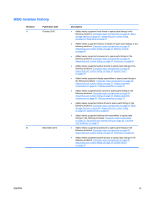
locations: Computer major components on page 20, Sequential part number listing on page 33, System board on page 76. ● Added newly supported display assemblies to spare parts listings in the following locations: Computer major components on page 20, Sequential part number listing on page 33 - HP G62-325CA | Service Guide - Page 4
iv MSG revision history ENWW - HP G62-325CA | Service Guide - Page 5
Safety warning notice WARNING! To reduce the possibility of heat-related injuries or of overheating the computer, do not place the computer directly on your lap or obstruct the computer air vents. Use the computer only on a hard, flat surface. Do not allow another hard surface, such as an adjoining - HP G62-325CA | Service Guide - Page 6
vi Safety warning notice ENWW - HP G62-325CA | Service Guide - Page 7
catalog ...19 Serial number location ...19 Computer major components ...20 Display assembly components ...27 Plastics Kit ...29 Mass storage devices ... ...39 Preliminary replacement requirements 39 Tools required ...39 Service considerations ...39 Plastic parts ...39 Cables and connectors 40 - HP G62-325CA | Service Guide - Page 8
cover ...59 Speaker assembly ...62 Power button board ...63 TouchPad button board ...64 Modem module ...65 USB board ...67 Power connector ...69 Display assembly ...70 System board ...76 RTC battery ...79 Fan/heat sink assembly ...81 Processor ...85 5 Setup Utility ...89 Computer Setup in Windows - HP G62-325CA | Service Guide - Page 9
...101 Computer specifications ...101 39.6-cm (15.6-in) display specifications 101 Hard drive specifications ...103 DVD±RW and CD from the recovery discs 112 Recovering from the dedicated recovery partition (select models only 112 Linux backup and recovery ...113 8 Connector pin assignments - HP G62-325CA | Service Guide - Page 10
10 Recycling ...123 Battery ...123 Display ...123 Index ...131 x ENWW - HP G62-325CA | Service Guide - Page 11
Product Name Processors Compaq Presario CQ62 Notebook PC HP G62 Notebook PC AMD Phenom™ N930 Processor (2.0 GHz, 2 core AMD Phenom II P860 Processor (2.0 GHZ 1.5 MB L2 cache 1066MHz)-Triple core 25 W (for model 1.2 only) AMD Phenom II N660 Processor 3.0 GHZ 2 MB AMD Phenom II P950 Processor (2.6 - HP G62-325CA | Service Guide - Page 12
Chipset Graphics Panel Memory Description HP G62 AMD Athlon II P360 Discrete Processor 2.3 GHZ 35 W (for model 1.2 only) AMD Champlain Supports dual-channel memory √ DDR3, 1066 MHz Supports up to 8 GB of system √ memory Supports the following configurations: ● 4096 MB (2048 MB × 2) HP G62 - HP G62-325CA | Service Guide - Page 13
56K V.92 data/fax MDC modem (computer models not equipped with a modem have a cover over the RJ-11 jack opening) Supports all worldwide certification requirements Integrated 10/100 network interface card (NIC) Discrete √ √ √ √ √ √ √ HP G62 UMA √ √ √ √ √ √ √ Compaq Presario CQ62 Discrete - HP G62-325CA | Service Guide - Page 14
HP G62 Realtek 8102E Wireless Integrated wireless local area network (WLAN) options by way of wireless module: 2 wireless antennas built into display assembly Support for no-WLAN option Support (select models only ) Digital Media Slot supporting SD, MMC, MS, MSPro, xD cards. Supports mini - HP G62-325CA | Service Guide - Page 15
adapter with localized cable plug support 90-W AC adapter with localized cable plug support Security Kensington Security Lock Serviceability End-user replaceable parts: AC adapter Battery (system) Hard drive Memory module Optical drive Mini-card devices Discrete √ √ √ √ √ HP G62 - HP G62-325CA | Service Guide - Page 16
6 Chapter 1 Product description ENWW - HP G62-325CA | Service Guide - Page 17
component identification Identifying the hardware Components included with the computer might vary by region and model. The illustrations in this chapter identify the standard features on most computer models. To see a list of hardware installed in the computer: 1. Select Start > My Computer. 2. In - HP G62-325CA | Service Guide - Page 18
Top components TouchPad Component (1) TouchPad light (2) TouchPad zone (3) Left TouchPad button (4) Right TouchPad button *This table describes factory settings. Description Off-Touchpad is on. Amber-Touchpad is off. Moves the pointer and selects or activates items on the screen. Press - HP G62-325CA | Service Guide - Page 19
Lights Component (1) TouchPad light (2) Caps lock light (3) Power light (4) Wireless light Description ● Off-TouchPad is enabled. ● Amber-TouchPad is disabled. On-Caps lock is on ● On-The computer is on. ● Flashing-The computer is in Sleep. ● Off-The computer is off or in Hibernation. ● - HP G62-325CA | Service Guide - Page 20
power settings, select Start > Control Panel > System and Security > Power Options. *This table describes factory settings. For information about changing factory settings, see the user guides located in Help and Support. 10 Chapter 2 External component identification ENWW - HP G62-325CA | Service Guide - Page 21
(4) Web browser key (5) Print key (6) Calculator key (7) fn key (8) Windows logo key (9) Windows applications key (10) Action keys Description Displays system information when pressed in combination with the fn key. Opens a new e-mail in your default e-mail client. Launches CyberLink - HP G62-325CA | Service Guide - Page 22
Display Component (1) Wireless antenna (2) (2) Internal microphone (3) Integrated webcam (select models only) (4) Webcam light (select models only) Description Sends and receives signals from one or more wireless devices. Records sound. Records audio and video and captures still - HP G62-325CA | Service Guide - Page 23
Right-side components Component (1) Optical drive (2) USB port (3) RJ-11 (modem) jack (select models only) (4) AC adapter light (5) Power connector (6) Security cable slot Description Reads and writes to optical discs. Connects an optional USB device. Connects a modem cable. ● Flashing - HP G62-325CA | Service Guide - Page 24
, or any compatible digital or audio component. NOTE: Depending on the computer model, the computer might include an HDMI port or a USB port at this powered stereo speakers, headphones, earbuds, a headset, or television audio. Supports the following optional digital card formats: ● Memory Stick (MS) - HP G62-325CA | Service Guide - Page 25
from the battery bay. Contains two memory module slots and, on select models, the wireless LAN (WLAN) device. CAUTION: To prevent an unresponsive module to restore computer functionality, and then contact technical support through Help and Support. Holds the hard drive. Wireless antennas At least - HP G62-325CA | Service Guide - Page 26
around the antennas free from obstructions. To review the wireless regulatory notices, see to the section of the Regulatory, Safety and Environmental Notices that applies to your country or region. These notices are located in Help and Support. 16 Chapter 2 External component identification ENWW - HP G62-325CA | Service Guide - Page 27
Additional hardware components Component (1) Power cord* (2) AC adapter (3) Battery* *Power cords vary in appearance by country or region. Description Connects an AC adapter to an AC outlet. Converts AC power to DC power. Powers the computer when the computer is not plugged into external - HP G62-325CA | Service Guide - Page 28
18 Chapter 2 External component identification ENWW - HP G62-325CA | Service Guide - Page 29
provide the computer serial number and model number located in the battery bay of number/Product number (p/n) (4) Warranty period (5) Model description ENWW Description The name affixed to the hardware components. The part number helps a service technician to determine what components and parts - HP G62-325CA | Service Guide - Page 30
Computer major components 20 Chapter 3 Illustrated parts catalog ENWW - HP G62-325CA | Service Guide - Page 31
Display assembly components on page 27. ● HP G62 biscotti computer models ● HP G62 biscotti computer models with webcam ● HP G62 silver computer models (for model 1.0 only) ● HP G62 silver computer models with webcam (for model 1.0 only) ● HP G62 matte black computer models (for model 1.0 only) ● HP - HP G62-325CA | Service Guide - Page 32
603785-001 ● 500 GB, 7200 rpm 634919-001 ● 320 GB, 7200 rpm 599055-001 ● 250 GB, 7200 rpm 599054-001 ● 160 GB, 7200 rpm (for models 1.0 and 1.1 only) 599053-001 ● Hard Drive Hardware Kit (not illustrated, includes bracket and screws) 599057-001 22 Chapter 3 Illustrated parts catalog ENWW - HP G62-325CA | Service Guide - Page 33
II N640 Processor (2.9 GHz, 2 MB total L2 cache, 1066 MHz)-Quad 616344-001 Core 35 W (for models 1.1 and 1.2 only) ● AMD Phenom II P840 Processor (1.9 GHz, 2 MB total L2 cache, 1066 MHz) (for models 1.1 and 1.2 only) 616335-001 ● AMD Phenom II N850 Processor (2.2 GHz, 2 MB total L2 cache, 1066 - HP G62-325CA | Service Guide - Page 34
AMD Phenom II P960 Processor (1.8 GHZ 2 MB L2 cache 1066 MHz)-Quad core 25 634689-001 W (for model 1.2 only) ● AMD Phenom II N870 Processor (2.3 GHZ 1.5 MB L2 cache 1333 MHz)-Triple core (for model 1.2 only) 635495-001 ● AMD Phenom II P860 Processor (2 GHZ 1.5 MB L2 cache 1066 MHz)-Triple core 25 - HP G62-325CA | Service Guide - Page 35
for use with: ● Biscotti computer models 599062-001 ● Matte black computer models 600651-001 ● Silver computer models (for model 1.0 only) 608112-001 ● Charcoal computer models (for models 1.1 and 1.2 only) 615588-001 ● Imperial blue computer models (for models 1.1 and 1.2 only) 622565-001 - HP G62-325CA | Service Guide - Page 36
Item (21) (22) Description ● Hard drive cover ● Memory module cover Spare part number 26 Chapter 3 Illustrated parts catalog ENWW - HP G62-325CA | Service Guide - Page 37
assembly components Item (1) (2) Description Display bezel ● Presario CQ62 with webcam and microphone modules ● Presario CQ62 with microphone module only ● HP G62 with webcam and microphone modules ● HP G62 with microphone module only Display bracket (with hinges) Spare part number 595190-001 - HP G62-325CA | Service Guide - Page 38
cable Display cable Display back cover (includes logo) for use with: ● HP G62 biscotti computer models ● HP G62 silver computer models (for model 1.0 only) ● HP G62 charcoal computer models (for models 1.1 and 1.2 only) ● HP G62 imperial blue computer models (for models 1.1 and 1.2 only) ● HP G62 - HP G62-325CA | Service Guide - Page 39
Plastics Kit Item Description Plastics kit (1) Hard drive bay cover (includes captive screws) (2) Wireless/memory module mini-card compartment cover (includes captive screw) Spare part number 595200-001 ENWW Plastics Kit 29 - HP G62-325CA | Service Guide - Page 40
Combo Drive with LightScribe for use with: ● Biscotti computer models ● Matte black computer models ● Silver computer models (for model 1.0 only) ● Charcoal computer models (for models 1.1 and 1.2 only) ● Imperial blue computer models (for models 1.1 and 1.2 only) 599062-001 600651-001 608112-001 - HP G62-325CA | Service Guide - Page 41
Item Description ● 320-GB 7200 RPM ● 250-GB 7200 RPM ● 160-GB 7200 RPM (for models 1.0 and 1.1 only) Hard drive hardware kit (not illustrated, includes bracket and screws) Spare part number 599055-001 599054-001 599053-001 600191-001 ENWW Mass storage devices 31 - HP G62-325CA | Service Guide - Page 42
90-W AC adapter 613153-001 Power cord, AC, 3 wire, black, 1.83-m (for use with both HP G62 and Presario CQ 62 computer models) for use in: ● Australia 490371-011 ● India 490371-D61 ● Japan (for models 1.1 and 1.2 only) ● Korea 490371-291 490371-AD1 ● North America 490371-001 ● the People - HP G62-325CA | Service Guide - Page 43
cord for use in North America Power cord for use in Australia Power cord for use in Thailand Power cord for use in Japan (for models 1.1 and 1.2 only) Power cord for use in the People's Republic of China Power cord for use in Taiwan Power cord for use in Korea Power - HP G62-325CA | Service Guide - Page 44
with Presario CQ62 with webcam and microphone modules Display enclosure for use with HP G62 biscotti computer models Display bezel for use with HP G62 with microphone module only Display bezel for use with HP G62 with webcam and microphone modules Display enclosure for use with Presario CQ62 matte - HP G62-325CA | Service Guide - Page 45
4313 802.11b/g/n 1x1 WiFi and 2070 Bluetooth 2.1+EDR Combo adapter (BT3.0+HS ready) Display hinge covers DVD±RW and CD-RW SuperMulti Double-Layer Combo Drive with LightScribe for use with matte black computer models Blu-ray ROM with LightScribe DVD±R/RW SuperMulti Double-Layer Drive for use with - HP G62-325CA | Service Guide - Page 46
-emitting diode display assembly for HP G62 silver computer models (for model 1.0 only) 39.6-cm (15.6-in) HD, light-emitting diode display assembly for HP G62 silver computer models with webcam (for model 1.0 only) Display enclosure for use with HP G62 silver computer models (for model 1.0 only) Top - HP G62-325CA | Service Guide - Page 47
1.1 and 1.2 only) 39.6-cm (15.6-in) HD, light-emitting diode display assembly for HP G62 imperial blue computer models with webcam (for models 1.1 and 1.2 only) Display enclosure for use with HP G62 imperial blue computer models (for models 1.1 and 1.2 only) DVD±RW and CD-RW SuperMulti Double-Layer - HP G62-325CA | Service Guide - Page 48
with LightScribe DVD±R/RW SuperMulti Double-Layer Drive for use with imperial blue computer models (for models 1.1 and 1.2 only) Top cover (includes TouchPad board) for use in imperial blue computer models (for models 1.1 and 1.2 only) Base enclosure with HDMI card reader for imperial blue computer - HP G62-325CA | Service Guide - Page 49
screwdriver ● Phillips P0 and P1 screwdrivers Service considerations Before disassembly or assembly procedures, review and adhere to all service considerations. NOTE: As you remove pressure only at the points designated in the maintenance instructions.. ENWW Preliminary replacement requirements 39 - HP G62-325CA | Service Guide - Page 50
Cables and connectors CAUTION: When servicing the computer, be sure that cables are placed in their proper locations during the reassembly process. Improper cable placement can damage the computer. Cables must - HP G62-325CA | Service Guide - Page 51
Grounding guidelines Electrostatic discharge damage Electronic components are sensitive to electrostatic discharge (ESD). Circuitry design and structure determine the degree of sensitivity. Networks built into many integrated circuits provide some protection, but in many cases, ESD contains enough - HP G62-325CA | Service Guide - Page 52
material. ● Use a wrist strap connected to a properly grounded work surface and use properly grounded tools and equipment. ● Use conductive field service tools, such as cutters, screwdrivers, and vacuums. ● When fixtures must directly contact dissipative surfaces, use fixtures made only of static - HP G62-325CA | Service Guide - Page 53
with ground cords of one megohm resistance ● Static-dissipative tables or floor mats with hard ties to the ground ● Field service kits ● Static awareness labels ● Material-handling packages ● Nonconductive plastic bags, tubes, or boxes ● Metal tote boxes ● Electrostatic voltage levels and - HP G62-325CA | Service Guide - Page 54
in 12 different sizes, that must be removed, replaced, or loosened when servicing the computer. Make special note of each screw size and location during contacting technical support. (1) Product name (2) Serial number (3) Product number (4) Warranty period (5) Model description (select models) 44 - HP G62-325CA | Service Guide - Page 55
Computer feet Description Rubber Feet Kit Spare part number 600849-001 The computer feet are adhesive-backed rubber pads. The feet attach to the base enclosure in the locations illustrated below. ENWW Component replacement procedures 45 - HP G62-325CA | Service Guide - Page 56
Battery Description 6 cell, 2.20-Ah, 47 Wh 6 cell, 2.55-Ah, 55 Wh Spare part number 593553-001 593554-001 Before disassembling the computer: 1. Shut down the computer. If you are unsure whether the computer is off or in Hibernation, turn on the computer, and then shut it down through the operating - HP G62-325CA | Service Guide - Page 57
1.1 and 1.2 only) 640 GB; 5400 RPM 500 GB; 7200 RPM 320 GB; 7200 RPM 250 GB; 7200 RPM 160 GB; 7200 RPM (for models 1.0 and 1.2 only) Hard drive hardware kit (not illustrated, includes connector, bracket, and screws) Spare part number 603787-001 603785-001 634919-001 599055-001 599054- - HP G62-325CA | Service Guide - Page 58
3. Lift the left side of the hard drive cover (2), swing it forward, and remove the cover (3). The hard drive cover is included in the plastics kit, spare part number 595200-001. 4. Remove the three Phillips PM2.5×5.0 screws (1) that secure the hard drive to the computer. 5. Use the hard drive - HP G62-325CA | Service Guide - Page 59
9. Grasp the two attached Mylar tabs and pull the bracket straight up to remove it from the hard drive (2). Reverse this procedure to install the hard drive. ENWW Component replacement procedures 49 - HP G62-325CA | Service Guide - Page 60
Combo Drive with LightScribe for use with: ● Biscotti computer models ● Matte black computer models ● Silver computer models (for model 1.0 only) ● Charcoal computer models (for models 1.1 and 1.2 only) ● Imperial blue computer models (for models 1.1 and 1.2 only) Blu-ray ROM with LightScribe DVD - HP G62-325CA | Service Guide - Page 61
3. Grasp the bezel and slide the optical drive out of the computer (2). 4. To replace the optical drive bracket, position the optical drive with the optical drive bracket toward you. 5. Remove the two Phillips PM2.0×3.0 screws (1) that secure the optical drive bracket to the optical drive. 6. Remove - HP G62-325CA | Service Guide - Page 62
WLAN module Description Spare part number Atheros AR9285 802.11 a/b/g/n 2x2 WiFi 580101-001 Atheros AR9285 802.11 a/b/g/n 2x2 WiFi adapter 580101-002 Realtek RTL8191SE 802.11b/g/n 1x1 WiFi Adapter 593533-001 Broadcom 4313 802.11b/g/n 1x1 WiFi Adapter 593836-001 Broadcom 4313 802.11b/g/n - HP G62-325CA | Service Guide - Page 63
4. Lift the cover off the computer (3). The mini-card compartment cover is included in the plastics kit, spare part number 595200-001. 5. Disconnect the main antenna cable (1) and the auxiliary antenna cable (2) from the wireless module. 6. Remove the Phillips PM2.0×3.0 screw (3) that secures the - HP G62-325CA | Service Guide - Page 64
replace the module and then receive a warning message, remove the module to restore computer functionality, and then contact technical support through Help and Support. NOTE: WLAN modules are designed with a notch (5) to prevent incorrect insertion into the WLAN module slot. Reverse this procedure - HP G62-325CA | Service Guide - Page 65
Memory module Description 1 GB, 1066 MHz DDR3 2 GB, 1066 MHz DDR3 4 GB, 1066 MHz DDR3 (for models 1.1 and 1.2 only) Spare part number 598859-001 598856-0011 599092-0011 Before removing the memory module: 1. Shut down the computer. If you are unsure whether - HP G62-325CA | Service Guide - Page 66
5. Spread the retaining tabs (1) on each side of the memory module slot to release the memory module. (The edge of the module opposite the slot rises away from the computer.) 6. Remove the module (2) by pulling it away from the slot at an angle. NOTE: Memory modules are designed with a notch (3) to - HP G62-325CA | Service Guide - Page 67
Keyboard Description For use in Canada For use in Japan (for models 1.1 and 1.2 only) For use in Korea For use in North America For use in Taiwan For use in Thailand Spare part number 595199-121 595199- - HP G62-325CA | Service Guide - Page 68
of the keyboard using a thin flat-bladed screwdriver. 6. Lift the rear edge of the keyboard (3), and set the keyboard back towards the display (4). 7. Release the zero insertion force (ZIF) connector (1) to which the keyboard cable is attached and disconnect the keyboard cable (2) from the system - HP G62-325CA | Service Guide - Page 69
For use with biscotti computer models For use with matte black computer models For use with silver computer models (for model 1.0 only) For use with charcoal computer models (for models 1.1 and 1.2 only) For use with imperial blue computer models (for models 1.1 and 1.2 only) Spare part number - HP G62-325CA | Service Guide - Page 70
PM2.5x6.5 screws on the base enclosure. The top cover screws are identified by a triangle icon embossed on the base enclosure. 3. Turn the computer display-side up with the front toward you. 4. Open the computer as far as possible. 5. Remove the Phillips PM2.5×6.0 screw that secures the top cover - HP G62-325CA | Service Guide - Page 71
6. Release the power button ZIF connector (1), speaker cable (2), touchpad ZIF connector (3), and touchpad button ZIF connector (4). 7. Lift the rear edge of the top cover (1) until the top cover disengages from the base enclosure. Remove the top cover (2). NOTE: The TouchPad is glued to the top - HP G62-325CA | Service Guide - Page 72
Speaker assembly Description Speaker assembly (includes cable) Spare part number 602744-001 Before removing the speaker assembly: 1. Shut down the computer. If you are unsure whether the computer is off or in Hibernation, turn on the computer, and then shut it down through the operating system. 2. - HP G62-325CA | Service Guide - Page 73
Power button board Description Power button board Spare part number 595204-001 Before removing the power button board: 1. Shut down the computer. If you are unsure whether the computer is off or in Hibernation, turn on the computer, and then shut it down through the operating system. 2. Disconnect - HP G62-325CA | Service Guide - Page 74
TouchPad button board Description Touchpad button board Spare part number 595203-001 Before removing the TouchPad button board: 1. Shut down the computer. If you are unsure whether the computer is off or in Hibernation, turn on the computer, and then shut it down through the operating system. 2. - HP G62-325CA | Service Guide - Page 75
Modem module Description All countries and regions except for Australia and New Zealand (for model 1.0 only) Australia and New Zealand (for model 1.0 only) Spare part number 510100-001 510100-011 Before removing the modem module: 1. Shut down the computer. If you are unsure whether the computer is - HP G62-325CA | Service Guide - Page 76
3. Lift up on the front of the modem module (2) to disconnect it from the system board. Reverse the above procedure to install the modem module, and be sure that the connector on the bottom of the modem module connects firmly into the system board. 66 Chapter 4 Removal and replacement procedures - HP G62-325CA | Service Guide - Page 77
USB board Description USB board Spare part number 595205-001 Before removing the USB board: 1. Shut down the computer. If you are unsure whether the computer is off or in Hibernation, turn on the computer, and then shut it down through the operating system. 2. Disconnect all external devices - HP G62-325CA | Service Guide - Page 78
Reverse this procedure to install the USB board. 68 Chapter 4 Removal and replacement procedures ENWW - HP G62-325CA | Service Guide - Page 79
Power connector Description Power connector (includes cable) Spare part number 602743-001 Before removing the power connector cable: 1. Shut down the computer. If you are unsure whether the computer is off or in Hibernation, turn on the computer, and then shut it down through the operating system. - HP G62-325CA | Service Guide - Page 80
(LED) display assembly for use in: ● HP G62 computer biscotti computer models ● HP G62 computer biscotti computer models with webcam ● HP G62 silver computer models (for model 1.0 only) ● HP G62 silver computer models with webcam (for model 1.0 only) ● HP G62 matte black computer models (for model - HP G62-325CA | Service Guide - Page 81
system board and release it from the clips that attach it to the system board. CAUTION: Support the display assembly when removing the display screws in the following steps. Failure to support the display assembly can result in damage to the assembly and other components. 6. Remove the four black - HP G62-325CA | Service Guide - Page 82
internal components, remove the following screw covers and screws: (1) Two mylar screw covers on the display bezel bottom edge (2) Two Phillips PM2.5×4.0 screws The display screw covers are included in the display screw kit, spare part number 595198-001. 9. Flex the inside edge of the top (1), the - HP G62-325CA | Service Guide - Page 83
bezel (4). Reverse this procedure to install the display bezel. 11. To replace the webcam module (select models only), lift the webcam module as far from the display enclosure as the webcam module cable allows. 12. Disconnect the webcam module cable (1) from the webcam module, and remove the webcam - HP G62-325CA | Service Guide - Page 84
Reverse this procedure to install the display hinge covers. 15. To replace the display panel, remove eight phillips PM2.5×6.0 screws (1) that secure the display panel to the display enclosure. 16. Remove the display panel (2) from the display enclosure. The display panel is available using the spare - HP G62-325CA | Service Guide - Page 85
panel brackets. 19. To replace the wireless antenna transceivers, lift up on the silver transceiver (1) and release the adhesive material from the display cover (2). 20. Lift up to remove the antenna transceivers (3). The wireless antenna transceivers with cable is available with the LCD cable kit - HP G62-325CA | Service Guide - Page 86
/1G PCA Discrete system board with card reader (for model 1.1 only) HD6370/512M Discrete system board (for model 1.2 only) HD6370/512M Discrete system board with card reader (for model 1.2 only) HD6370/1G Discrete system board (for model 1.2 only) HD6370/1G Discrete system board with card reader - HP G62-325CA | Service Guide - Page 87
c. Keyboard (see Keyboard on page 57) d. Top cover (see Top cover on page 59) e. Speaker assembly (see Speaker assembly on page 62) f. Display assembly (see Display assembly on page 70) Remove the following cables from the system board: ● Power connector cable (see Power connector on page 69) ● USB - HP G62-325CA | Service Guide - Page 88
5. To replace the modem module cable, remove the RJ-11 connector cable from the clips (1), and then lift the connector straight up (2) and out of the computer. The modem module cable is available using spare part number 595201-001. Reverse this procedure to install the modem module cable. When - HP G62-325CA | Service Guide - Page 89
d. Keyboard (see Keyboard on page 57) e. Top cover (see Top cover on page 59) f. Speaker assembly (see Speaker assembly on page 62) g. Display assembly (see Display assembly on page 70) h. System board (see System board on page 76) Remove the RTC battery: 1. Turn the system board upside down. 2. Use - HP G62-325CA | Service Guide - Page 90
3. Lift the battery (2) out of the computer. Reverse this procedure to install the RTC battery. 80 Chapter 4 Removal and replacement procedures ENWW - HP G62-325CA | Service Guide - Page 91
assembly (see Display assembly on page 70) g. System board (see System board on page 76) Remove the fan/heat assembly (fan/heat sink appearance might vary): NOTE: Steps 1 through 4 apply only to computer models equipped with graphics subsystems having UMA memory. 1. Turn the system board right - HP G62-325CA | Service Guide - Page 92
side to detach the assembly. 4. Remove the fan/heat sink assembly (2) by lifting straight up. NOTE: Steps 5 through 8 apply only to computer models equipped with graphics subsystems having discrete memory. 1. Turn the system board right-side up, with the front toward you. 82 Chapter 4 Removal and - HP G62-325CA | Service Guide - Page 93
2. Disconnect the fan cable from the system board. 3. Loosen the three Phillips captive screws (1) and three Phillips spring-loaded captive screws (2) that secure the fan/heat sink assembly. NOTE: Due to the adhesive quality of the thermal material located between the fan/heat sink assembly and - HP G62-325CA | Service Guide - Page 94
NOTE: Thermal pads and thermal paste are included with all fan/heat sink assembly, system board, and processor spare part kits. The following illustration shows the locations for thermal material on systems with UMA graphics subsystems. The thermal material must be thoroughly cleaned from the - HP G62-325CA | Service Guide - Page 95
, 3.6 GT/s)-Dual Core 25 W 594173-001 AMD Athlon II N330 Processor (2.3 GHz, 1 MB L2 cache, 1066 MHz, 3.2 GT/s)-Dual Core 35 W 594164-001 (for model 1.0 only) AMD Athlon II P320 Processor (2.1 GHz, 1 MB L2 cache, 1066 MHz, 3.2 GT/s)-Dual Core 25 W 594165-001 AMD Sempron II V120 Processor (2.2 GHz - HP G62-325CA | Service Guide - Page 96
core 35 W (for model 1.2 only) 635494-001 AMD Phenom II P650 Processor (2.6 GHZ 2 MB L2 cache)-25 W (for model 1.2 only) 634687-001 AMD page 59) e. Speaker assembly (see Speaker assembly on page 62) f. Display assembly (see Display assembly on page 70) g. System board (see System board on page - HP G62-325CA | Service Guide - Page 97
2. Lift the processor (2) straight up and remove it. NOTE: The gold triangle (3) on the processor must be aligned with the triangle icon (4) embossed on the processor socket when you install the processor. Reverse this procedure to install the processor. ENWW Component replacement procedures 87 - HP G62-325CA | Service Guide - Page 98
88 Chapter 4 Removal and replacement procedures ENWW - HP G62-325CA | Service Guide - Page 99
view the drives installed on the computer, select Start > Computer. On models with a secondary hard drive (drive D), the optical drive becomes drive -left corner of the screen, press the esc key. When the Startup Menu displays, press the f10 key. 2. Use the arrow keys to select System Configuration - HP G62-325CA | Service Guide - Page 100
in Setup Utility Because Setup Utility is not Windows based, it does not support the TouchPad. Navigation and selection are by keystroke. ● To choose a restarting the computer. When the Press the ESC key for Startup Menu message displays in the lower-left corner of the screen, press the f10 key. - - HP G62-325CA | Service Guide - Page 101
already running, begin at step 2. 1. Open Setup Utility by turning on or restarting the computer. When the Press the ESC key for Startup Menu message displays in the lower-left corner of the screen, press the f10 key. - or - Open Setup Utility by turning on or restarting the computer. When the - HP G62-325CA | Service Guide - Page 102
the Setup Utility menus are not displayed, press the esc key to return to the menu display. Then use the arrow keys menu items listed in this chapter might not be supported by the computer. Main menu Select System information keyboard controller version (select models only). Security menu Select - HP G62-325CA | Service Guide - Page 103
System Configuration menu Select Language Support Button Sound (select models only) Virtualization Technology (select models only) Processor C6 State (select models only) LAN Power Saving (select models only) Card Reader/1394 Power Saving (select models only) Fan Always On Action Keys Mode Boot - HP G62-325CA | Service Guide - Page 104
in this guide might not be supported by the computer. NOTE: Pointing devices are not supported in Computer and when the F10=ROM Based Setup message displays in the lower-left corner of the screen, File > Ignore Changes And Exit. Then follow the instructions on the screen. ● To save your preferences - HP G62-325CA | Service Guide - Page 105
, and then pressing the f10 key when the F10 = ROM Based Setup message displays in the lower-left corner of the screen. 2. Use the arrow keys to select keys to select File > Save Changes And Exit. Then follow the instructions on the screen. Your preferences go into effect when the computer restarts. - HP G62-325CA | Service Guide - Page 106
this section provide an overview of Computer Setup options. NOTE: Some of the Computer Setup menu items listed in this chapter might not be supported by the computer. File menu Select System information Restore Defaults Ignore Changes And Exit Save Changes And Exit To do this ● View identification - HP G62-325CA | Service Guide - Page 107
Security menu NOTE: Some of the menu items listed in this section might not be supported by the computer. Select Setup Password Power-On Password Password Options DriveLock Passwords System IDs Disk Sanitizer To do this Enter, change, or delete a setup - HP G62-325CA | Service Guide - Page 108
disk ◦ 6th boot device-Network controller ● Swap the functions of the fn key and left ctrl key. ● Enable/disable USB legacy support. When enabled, USB legacy support allows the following: ◦ Use of a USB keyboard in Computer Setup even when the operating system is not running. ◦ Startup from bootable - HP G62-325CA | Service Guide - Page 109
Select Built-in device options Port options To do this ● Enable/disable embedded WLAN Device Radio. ● Enable/disable embedded Bluetooth Device Radio. ● Enable/disable Network Interface Controller (NIC) ● Enable/disable LAN/WLAN Switching. ● Enable/disable Wake on LAN. ● Enable/disable the - HP G62-325CA | Service Guide - Page 110
100 Chapter 5 Setup Utility ENWW - HP G62-325CA | Service Guide - Page 111
ft) NOTE: Applicable product safety standards specify thermal limits for plastic surfaces. The computer operates well within this range of temperatures. 39.6-cm (15.6-in) display specifications Dimensions ENWW Computer specifications 101 - HP G62-325CA | Service Guide - Page 112
Height Width Diagonal Number of colors Contrast ratio Brightness Pixel resolution Pitch Format Configuration Backlight Character display Total power consumption Viewing angle 21.0 cm (8.27 in) 35.9 cm (14.1 in) 39.6 cm (15.6) Up to 16.8 million 300:1 (typical) 200 nits (typical) 0. - HP G62-325CA | Service Guide - Page 113
referring to hard drive storage capacity. Actual accessible capacity is less. Actual drive specifications may differ slightly. NOTE: Certain restrictions and exclusions apply. Contact technical support for details. ENWW Hard drive specifications 103 - HP G62-325CA | Service Guide - Page 114
DVD±RW and CD-RW SuperMulti Double-Layer Combo Drive with LightScribe specifications Applicable disc Read Write Random access time DVD CD Cache buffer Data transfer rate 24X CD-ROM 8X DVD-ROM 24X CD-R 16X CD-RW 8X DVD+R 4X DVD+RW 8X DVD-R 4X DVD-RW 2.4X DVD+R(9) 5X DVD-RAM Transfer mode CD-DA, CD - HP G62-325CA | Service Guide - Page 115
Blu-ray ROM with LightScribe DVD±R/RW SuperMulti Double-Layer Drive specifications Applicable disc Read Write Random access time BD DVD CD Cache buffer Data transfer rate 24X CD-ROM 8X DVD-ROM 4X BD 24X CD-R 16X CD-RW 8X DVD+R 4X DVD+RW 8X DVD-R 4X DVD-RW 2.4X DVD+R(9) 5X DVD-RAM 1X BD-ROM 1X BD-R - HP G62-325CA | Service Guide - Page 116
input/output (I/O) ports, interrupt request (IRQ) lines, and memory addresses. If two devices require the same resource and create a device conflict, manually change the resource settings in Device Manager to be sure each setting is unique. CAUTION: Improperly changing resource settings can disable - HP G62-325CA | Service Guide - Page 117
a reasonably current backup. Tools provided by the operating system and HP Recovery Manager software are designed to help you with the following tasks or instability. Recovery Manager works from a dedicated recovery partition (select models only) on the hard drive or from recovery discs you create. - HP G62-325CA | Service Guide - Page 118
model, you might have one of the following backup and recovery solutions: ● Roxio BackOnTrack ● HP Recovery Manager NOTE: For detailed information, perform a search for these topics in Help and Support. Creating recovery discs HP the on-screen instructions. 108 Chapter 7 Backup and recovery ENWW - HP G62-325CA | Service Guide - Page 119
screen shot can be a time-saver if you have to reset your preferences. To copy the screen and paste it into a word-processing document steps: 1. Display the screen. 2. Copy the screen: To copy only the active window, press alt+prt sc. To copy the entire screen, press prt sc. 3. Open a word - HP G62-325CA | Service Guide - Page 120
1. Select Start > All Programs > Maintenance > Backup and Restore. 2. Follow the on-screen instructions to set up and create a backup. NOTE: Windows includes the User Account Control feature to Windows settings. See Help and Support for more information. 110 Chapter 7 Backup and recovery ENWW - HP G62-325CA | Service Guide - Page 121
Follow the on-screen instructions. Performing a recovery NOTE: You can recover only files that you have previously backed up. HP recommends using Recovery works from recovery discs or from a dedicated recovery partition (select models only) on the hard drive. However, if the computer includes - HP G62-325CA | Service Guide - Page 122
computer. 3. Follow the on-screen instructions. Recovering from the dedicated recovery partition (select models only) NOTE: If the computer includes then press esc while the "Press the ESC key for Startup Menu" message is displayed at the bottom of the screen. Then, press f11 while the "Press - HP G62-325CA | Service Guide - Page 123
at the factory. Software, drivers, and updates not installed by HP must be manually reinstalled. Personal files must be restored from a backup. To for recovery" message appears on the screen. 3. Follow the on-screen instructions. NOTE: If you are unable to boot (start up) the computer from the - HP G62-325CA | Service Guide - Page 124
114 Chapter 7 Backup and recovery ENWW - HP G62-325CA | Service Guide - Page 125
8 Connector pin assignments Audio-out (headphone) Pin Signal 1 Audio out, left channel 2 Audio out, right channel 3 Ground Audio-in (microphone) Pin Signal 1 Audio signal in 2 Audio signal in 3 Ground ENWW Audio-out (headphone) 115 - HP G62-325CA | Service Guide - Page 126
External monitor Pin Signal 1 Red analog 2 Green analog 3 Blue analog 4 Not connected 5 Ground 6 Ground analog 7 Ground analog 8 Ground analog 9 +5 VDC 10 Ground 11 Monitor detect 12 DDC 2B data 13 Horizontal sync 14 Vertical sync 15 DDC 2B clock 116 Chapter 8 - HP G62-325CA | Service Guide - Page 127
RJ-11 (modem) Pin 1 2 3 4 5 6 RJ-45 (network) Signal Unused Tip Ring Unused Unused Unused Pin 1 2 3 4 5 6 7 8 ENWW Signal Transmit + Transmit Receive + Unused Unused Receive Unused Unused RJ-11 (modem) 117 - HP G62-325CA | Service Guide - Page 128
HDMI Pin 1 2 3 4 5 6 7 8 9 10 11 12 13 14 15 16 17 18 19 20 Signal TMDS data 2+ TMDS data 2 shield TMDS data 2- TMDS data 1+ TMDS data 1shield TMDS data 1- TMDS data 0+ TMDS data 0 shield TMDS data 0- TMDS clock+ TMDS clock shield TMDS clock- CEC No connect DDC clock DDC data Ground +5V power Hot - HP G62-325CA | Service Guide - Page 129
Universal Serial Bus Pin Signal 1 +5 VDC 2 Data - 3 Data + 4 Ground ENWW Universal Serial Bus 119 - HP G62-325CA | Service Guide - Page 130
120 Chapter 8 Connector pin assignments ENWW - HP G62-325CA | Service Guide - Page 131
9 Power cord set requirements The wide range input feature of the computer permits it to operate from any line voltage from 100 to 120 volts AC or from 220 to 240 volts AC. The 3-conductor power cord set included with the computer meets the requirements for use in the country or region where the - HP G62-325CA | Service Guide - Page 132
Requirements for specific countries or regions Country/region Accredited agency Applicable note number Australia EANSW 1 Austria OVE 1 Belgium CEBC 1 Canada CSA 2 Denmark DEMKO 1 Finland FIMKO 1 France UTE 1 Germany VDE 1 Italy IMQ 1 Japan METI 3 The Netherlands - HP G62-325CA | Service Guide - Page 133
computer battery disposal. Display WARNING! The backlight display components. The only components intended for recycling purposes are the liquid crystal display HP product contains mercury in the backlight in the display disassembly instructions for the display assembly. The display assembly must - HP G62-325CA | Service Guide - Page 134
screws (2) that secure the display bezel to the display assembly. 2. Lift up and out on the left and right inside edges (1) and the top and bottom inside edges (2) of the display bezel until the bezel disengages from the display assembly. 3. Remove the display bezel (3). 124 Chapter 10 Recycling - HP G62-325CA | Service Guide - Page 135
the two screws (1) that secure each hinge to the display enclosure and lift up to remove the display hinge covers (2). 5. Remove all screws (1) that secure the display panel assembly to the display enclosure. 6. Remove the display panel assembly (2) from the display enclosure. ENWW Display 125 - HP G62-325CA | Service Guide - Page 136
-edged tool to cut the tape (1) that secures the sides of the display panel to the display panel frame. 9. Remove the display panel frame (2) from the display panel. 10. Remove the screws (1) that secure the backlight cover to the display panel. 11. Lift the top edge of the backlight cover (2) and - HP G62-325CA | Service Guide - Page 137
14. Remove the backlight cables (1) from the clip (2) in the display panel. 15. Turn the display panel upside down. 16. Remove the backlight frame from the display panel. WARNING! The backlight contains mercury. Exercise caution when removing and handling the backlight to avoid damaging this - HP G62-325CA | Service Guide - Page 138
17. Remove the backlight from the backlight frame. 18. Disconnect the display cable (1) from the LCD panel. 19. Remove the screws (2) that secure the LCD panel to the display rear panel. 20. Release the LCD panel (3) from the display rear panel. 21. Release the tape (4) that secures the LCD panel - HP G62-325CA | Service Guide - Page 139
22. Remove the LCD panel. 23. Recycle the LCD panel and backlight. ENWW Display 129 - HP G62-325CA | Service Guide - Page 140
130 Chapter 10 Recycling ENWW - HP G62-325CA | Service Guide - Page 141
button sound 93 buttons power 10 TouchPad right/left 8 C cables, service considerations 40 camera module removal 73 spare part number 73 camera, product 45 117 Universal Serial Bus (USB) 119 connector, power 13 connectors, service considerations 40 cord, power 17 D Diagnostics menu 93, 97 Digital - HP G62-325CA | Service Guide - Page 142
display cable kit spare part number 28 display component recycling 123 display components illustrated 27 spare part numbers 27 display enclosure illustrated 27 display hinge kit, spare part number 28 display inverter illustrated 27 display language support 93 latch, battery release 15 legacy support, - HP G62-325CA | Service Guide - Page 143
29 removal 55 spare part number 55 model name 1 modem jack, pin assignments 117 State 93 product description audio 3 camera 3 chipset 2 display panel 2 Ethernet 3 external media cards 4 graphics 2 90 serial number 19, 44 service considerations 39 serviceability, product description 5 setup utility - HP G62-325CA | Service Guide - Page 144
-ray ROM with LightScribe DVD±R/RW SuperMulti DL Drive 105 computer 101 display 101 DVD ±RW SuperMulti Double- Layer Drive with LightScribe 104 hard 106 starting Setup Utility 89 static-shielding materials 43 stringent security 97 supported discs 108 system board removal 76 spare part numbers 22, 76 - HP G62-325CA | Service Guide - Page 145
- HP G62-325CA | Service Guide - Page 146
-
 1
1 -
 2
2 -
 3
3 -
 4
4 -
 5
5 -
 6
6 -
 7
7 -
8
-
9
-
10
-
11
-
12
-
13
-
14
-
15
-
16
-
17
-
18
-
19
-
20
-
21
-
22
-
23
-
24
-
25
-
26
-
27
-
28
-
29
-
30
-
31
-
32
-
33
-
34
-
35
-
36
-
37
-
38
-
39
-
40
-
41
-
42
-
43
-
44
-
45
-
46
-
47
-
48
-
49
-
50
-
51
-
52
-
53
-
54
-
55
-
56
-
57
-
58
-
59
-
60
-
61
-
62
-
63
-
64
-
65
-
66
-
67
-
68
-
69
-
70
-
71
-
72
-
73
-
74
-
75
-
76
-
77
-
78
-
79
-
80
-
81
-
82
-
83
-
84
-
85
-
86
-
87
-
88
-
89
-
90
-
91
-
92
-
93
-
94
-
95
-
96
-
97
-
98
-
99
-
100
-
101
-
102
-
103
-
104
-
105
-
106
-
107
-
108
-
109
-
110
-
111
-
112
-
113
-
114
-
115
-
116
-
117
-
118
-
119
-
120
-
121
-
122
-
123
-
124
-
125
-
126
-
127
-
128
-
129
-
130
-
131
-
132
-
133
-
134
-
135
-
136
-
137
-
138
-
139
-
140
-
141
-
142
-
143
-
144
-
145
-
146
 |
 |

Compaq Presario CQ62 Notebook
PC and HP G62 Notebook PC
Maintenance and Service Guide
SUMMARY
This guide is a troubleshooting reference used for maintaining and servicing the computer. It provides
comprehensive information on identifying computer features, components, and spare parts;
troubleshooting computer problems; and performing computer disassembly procedures.