HP Indigo 7800 ITM Bearings Alignment
HP Indigo 7800 Manual
 |
View all HP Indigo 7800 manuals
Add to My Manuals
Save this manual to your list of manuals |
HP Indigo 7800 manual content summary:
- HP Indigo 7800 | ITM Bearings Alignment - Page 1
HP Indigo 7000 Digital Press, HP Indigo 7500 Digital Press, HP Indigo 7600 Digital Press, HP Indigo 7800 Digital Press, HP Indigo 7900 Digital Press, HP Indigo 7r Digital Press, HP Indigo WS6000 Digital Press, HP Indigo WS6000p Digital Press, HP Indigo WS6600 Digital Press, HP Indigo WS6600p Digital - HP Indigo 7800 | ITM Bearings Alignment - Page 2
to use this document...2 Prerequisites ...2 Estimated installation time ...2 Special skills ...2 Special jigs and tools ...2 2 Verifying the press leveling for HP Indigo 7000 Digital Press and HP Indigo 7500 Digital Press 3 3 Verifying the press leveling for HP Indigo WS6000 Digital Press and HP - HP Indigo 7800 | ITM Bearings Alignment - Page 3
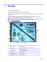
the end of the alignment, the ITM drum will be balanced and parallel to the other drums. NOTE: Before you use the ITM bearing alignment jig, verify the press leveling. Figure 1-1 ITM bearing alignment jig 1 Front and rear chucks 2 Front and rear caps 3 Alignment jig shaft 4 Drums rotation stopper - HP Indigo 7800 | ITM Bearings Alignment - Page 4
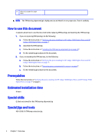
about how to use this document while replacing ITM bearings and resetting the ITM bearings. 1. If you are replacing ITM bearings, do the following: a. Follow the instructions in "Verifying the press leveling for HP Indigo 7000 Digital Press and HP Indigo 7500 Digital Press on page 3". b. Assemble - HP Indigo 7800 | ITM Bearings Alignment - Page 5
2 Verifying the press leveling for HP Indigo 7000 Digital Press and HP Indigo 7500 Digital Press Follow the instructions in Press Engine Leveling for Commercial HP Indigo Digital Presses (CA393‑04990). Verifying the press leveling for HP Indigo 7000 Digital Press and HP Indigo 7500 Digital Press 3 - HP Indigo 7800 | ITM Bearings Alignment - Page 6
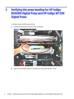
3 Verifying the press leveling for HP Indigo WS6000 Digital Press and HP Indigo W7200 Digital Press Follow these steps to verify the press leveling. 1. Put the 0.02 mm/m level at the input side on the IBS idler. Figure 3-1 Leveling the input side of the PE 2. Adjust the leveling - HP Indigo 7800 | ITM Bearings Alignment - Page 7
. 6. Make sure that the wheels are raised above the ground at all times. 7. Recheck the leveling on the press at the input and exit sides. 8. Reinstall the UL protective cover (2 x M4 Allen screws). Verifying the press leveling for HP Indigo WS6000 Digital Press and HP Indigo W7200 Digital Press 5 - HP Indigo 7800 | ITM Bearings Alignment - Page 8
power at the wall until instructed otherwise in this document. 2. At the press front, remove the following components as shown in the figures below: a. External heater lamps and hood b. Cleaning station and charge roller c. For the HP Indigo 7000 Digital Press: Exit blanket ventilation, PTE unit - HP Indigo 7800 | ITM Bearings Alignment - Page 9
d. IR sensors of ITM drum e. ITM internal lamp wires from their connectors f. ITM carbon brushes Removing components from the front of press 7 - HP Indigo 7800 | ITM Bearings Alignment - Page 10
Removing components from the rear of press Removal of components from the rear of press. 1. At the rear of the press, remove the following components in the following order: a. External heating suction air conduit b. Flywheel c. Exit unit suction exhaust d. E-H duct from EBV suction blower e. ITM - HP Indigo 7800 | ITM Bearings Alignment - Page 11
g. E-H duct from EBV suction blower Removing components from the rear of press 9 - HP Indigo 7800 | ITM Bearings Alignment - Page 12
2. For the HP Indigo 6000, HP Indigo 6600, and HP Indigo W7200 Digital presses, remove the grease reservoir as shown below. 3. For the HP Indigo 7000 and HP Indigo 7500 Digital Presses, disconnect the following: Figure 4-1 Rear of press 1 ITM IR sensor installed on the PSTB prevention bracket 2 - HP Indigo 7800 | ITM Bearings Alignment - Page 13
Removal of components from the input side of press. 1. For the HP Indigo WS6000 Digital Press and the HP Indigo W7200 Digital Press, remove the BCS. 2. For the HP Indigo 7000 Digital Press and HP Indigo 7500 Digital Press, use a Phillips screwdriver to remove the PSTB mechanism. Figure 4-2 Removing - HP Indigo 7800 | ITM Bearings Alignment - Page 14
to extract the ITM bearings. 1. Remove the ITM drum lamps: Figure 5-1 Removing the lamp holder bracket Carefully pull the lamps out of the ITM drum using the ITM lamp extraction jig (MJX-3299-01). 12 Chapter 5 Aligning the ITM bearings - HP Indigo 7800 | ITM Bearings Alignment - Page 15
Figure 5-2 Removing the ITM lamps 2. At the press front, use the ITM bearing front locking tool to remove the front locking ring. a. Release the four M4x20 screws holding the front locking ring (flange). Figure 5-3 Front - HP Indigo 7800 | ITM Bearings Alignment - Page 16
the drum rotation stopper d. Slowly turn the drum counter-clockwise until the weight of the drum is stopped by the drum rotation stopper. e. Using a ratchet wrench and the ITM bearing locking tool, turn the center ring counterclockwise to unlock it. Figure 5-5 ITM bearing front locking tool 14 - HP Indigo 7800 | ITM Bearings Alignment - Page 17
with IPA and put it in a safe place for later use. Figure 5-6 Front locking ring removed g. Remove the drum rotation stopper. h. Remove the front bearing to the press wall. See Figure 5-13 4 M6x20 screws on page 19. i. Place spacers between the ITM drum and the rear press wall. You can take a - HP Indigo 7800 | ITM Bearings Alignment - Page 18
j. Use the extraction screws to extract the rear bearing from the press wall by 10 - 15 mm. Do not completely remove the bearing. See figure below. 3. At the press rear, remove the locking ring (flange) by removing the (a) 8 screws (12 screws for new ITM drum)You may need to release the (b) 3 - HP Indigo 7800 | ITM Bearings Alignment - Page 19
Figure 5-9 Rear ITM bearing locking ring 4. Remove the four screws that attach the rear bearing to the press wall. Figure 5-10 ITM bearing screws Extracting the ITM bearings 17 - HP Indigo 7800 | ITM Bearings Alignment - Page 20
wall. You can take a 300 gsm paper and fold it to a thickness of 3 mm, and use it as a spacer. Figure 5-11 Spacer 6. Using the extraction screws, extract the rear bearing from the press wall by 10 - 15 mmDo not completely remove the bearing. Installing the ITM bearing alignment jig Follow these - HP Indigo 7800 | ITM Bearings Alignment - Page 21
3. For both the front and rear ITM bearings, install and tighten the 4 M6x20 screws that attach the bearings to the press walls. Figure 5-13 4 M6x20 screws 4. Loosen, by two turns, the three cover screws on the front and rear ITM bearing. Figure 5-14 Front and rear - HP Indigo 7800 | ITM Bearings Alignment - Page 22
a. Install the rear locking ring using two opposite screws. Figure 5-15 Rear locking ring with two opposite screws b. Verify that the PIP and ITM gears are aligned. c. Remove the two screws. d. Remove the rear locking ring. 20 Chapter 5 Aligning the ITM bearings - HP Indigo 7800 | ITM Bearings Alignment - Page 23
Indigo WS6000 Digital Press and HP Indigo W7200 Digital Press, insert a 17 - 18 mm thick bundle of paper between the ITM drum and the impression roller to decrease the load on the ITM bearings. Then try to push the ring again. NOTE: The thick bundle of paper supports the drum's weight but should not - HP Indigo 7800 | ITM Bearings Alignment - Page 24
8. From the front of the press, slide one of the chucks all the way into the ITM bearingNote that Figure 5-18 Installing the rear chuck on the ITM bearing alignment jig shaft 10. From the rear of the press, slide the chuck (which is attached to the jig shaft) through the ITM drum, all the way into - HP Indigo 7800 | ITM Bearings Alignment - Page 25
initial tightening to the rear and front chucksStart with the rear. 12. Using the hook spanners, tighten the rear and front chucks with relatively low force. Figure 5-20 Tightening the ITM bearing alignment jig chuck 13. Using the hook spanners tighten the rear and front chucks completely (but do - HP Indigo 7800 | ITM Bearings Alignment - Page 26
14. Install the rear and front caps, on the rear and front chucks, using 3 M4 screws that go into the ITM lamps holder threads. Figure 5-21 Installing the caps on rear and front chucks NOTE: Until this stage, the - HP Indigo 7800 | ITM Bearings Alignment - Page 27
2. Uninstall each cover screw (one at a time)Clean each screw with IPAAdd Loctite 242/Omnifit 100. Reinstall each cover screw. Figure 5-23 Front and rear bearing cover screws 3. Set the torque wrench to 1 Nm force. 4. Tighten the 3 rear bearing cover screws as shown below. Start at the screw shown - HP Indigo 7800 | ITM Bearings Alignment - Page 28
jig Removal of ITM bearing alignment jig. 1. Uninstall the front and rear caps from the front and rear chucksPlace it back in the case. 2. Using the hook spanners loosen the front and rear chucks. 3. Remove the rear chuck along with the ITM bearing alignment jig shaft. 4. Disassemble the rear - HP Indigo 7800 | ITM Bearings Alignment - Page 29
6. Place the other parts and tools back in the case, as shown below. Figure 5-25 Placing the ITM bearing alignment jig back in the case Finishing ITM bearings alignment Follow these steps to finish ITM bearings alignment. 1. On the rear bearing, install the rear ITM locking ring as follows: a. - HP Indigo 7800 | ITM Bearings Alignment - Page 30
Figure 5-26 Cleaning threads in ITM drum shaft b. Thoroughly clean the inside of the locking ring area with IPA. Figure 5-27 Cleaning inside the locking ring area 28 Chapter 5 Aligning the ITM bearings - HP Indigo 7800 | ITM Bearings Alignment - Page 31
g. Install the four/eight screws that goes into the ITM drum, with Nordlock washers. This will pull the ITM drum towards the rear of the press. NOTE: To avoid mistakes, pay attention to the way the Nordlock washer is installed. Finishing ITM bearings alignment 29 - HP Indigo 7800 | ITM Bearings Alignment - Page 32
h. Tighten the four/eight screws in a diagonal pattern. Figure 5-30 4/8 screws into the ITM drum with Nordlock washers i. Install the four "push" screws, with a drop of Loctite242/Omnifit100 on the screw threads. Wipe away any glue excess from the thread, if necessary. j. Screw in the four "push" - HP Indigo 7800 | ITM Bearings Alignment - Page 33
k. Tighten the four "push" screws in a diagonal pattern. Figure 5-31 Four "push" screws into the locking ring with Loctite/Omnifit l. Re-tighten the first four/eight screws in a diagonal pattern. m. Re-tighten the four "push" screws in a diagonal pattern. 2. On the front bearing, grease the front - HP Indigo 7800 | ITM Bearings Alignment - Page 34
torque jumps. Figure 5-33 Tightening the front locking ring with the toque wrench c. Manually rotate and jiggle the drums to release the inner bearing if it is stuck on the drum shaft. d. Retighten the locking ring again using a torque wrench that is set to 4 Nm. e. Repeat steps c. andd. until the - HP Indigo 7800 | ITM Bearings Alignment - Page 35
6. Turn the brass lock mechanism clockwise to lock the drum. Figure 5-34 Installing the drum rotation stopper 7. Slowly turn the drum clockwise until the weight of the drum is stopped by the drum rotation stopper. Finishing ITM bearings alignment 33 - HP Indigo 7800 | ITM Bearings Alignment - Page 36
to the angle marked on the bearing cover (+/- 3°). Figure 5-35 Figure Angle marked on bearing cover 9. If the number is less than 29, then use the following conversion table to convert the number to a different angle of closure. 10. If you cannot reach the desired angledo the following: a. Unlock - HP Indigo 7800 | ITM Bearings Alignment - Page 37
Install four new M4 x 20 mm screws on the front bearing ring (flange) as follows: a. Clean the threads (both the screw and hole) using IPA or equivalent. b. Use a clean wipe to absorb the remaining IPA. Do not touch the threads after this. c. Apply Loctite 7471 primer/activator evenly to the threads - HP Indigo 7800 | ITM Bearings Alignment - Page 38
components It explains how to reinstall the press components. Reinstalling the ITM area components Reinstall the ITM area components. 1. Reinstall the safety guard. 2. and back. Reinstalling the other components Reinstall the other components of ITM. 36 Chapter 6 Reinstalling the press components - HP Indigo 7800 | ITM Bearings Alignment - Page 39
. Figure 6-2 PSTB IR connector and air tube 2. For the HP Indigo WS6000 Digital Press and the HP Indigo W7200 Digital Press, reinstall the IR sensors bracket. 3. For the HP Indigo WS6000 Digital Press and the HP Indigo W7200 Digital Press, reinstall the BCS. 4. Reinstall the external heating hood - HP Indigo 7800 | ITM Bearings Alignment - Page 40
Follow these steps to adjust and test the system. 1. Install a new blanket. 2. Run the Harmonic and Torque Compensation wizard. 3. Set the press status to Ready. The press automatically performs the Second Transfer calibration at the end of the Get Ready process. 4. Run the First Transfer wizard - HP Indigo 7800 | ITM Bearings Alignment - Page 41
N/A Shay Drukman Dany Leonov Yuval Bloomberg / Isaac Diwan Sigal Aknin Yehudah Goldberg / Chaim Mateh Printing instructions Follow these recommendations to achieve the best print quality. Paper weight Page size Printing Simplex/duplex Color Finishing 80 g A4, Letter, or 8.27 x 11.00 in (21 x 27 - HP Indigo 7800 | ITM Bearings Alignment - Page 42
be copied, reproduced or distributed in any form or medium, or disclosed to any third party in any manner, without prior written authorization of HP. The copyright notice, which appears in this document, is purely precautionary and shall not be deemed to constitute publication or intent to publish
-
 1
1 -
 2
2 -
 3
3 -
 4
4 -
 5
5 -
 6
6 -
 7
7 -
8
-
9
-
10
-
11
-
12
-
13
-
14
-
15
-
16
-
17
-
18
-
19
-
20
-
21
-
22
-
23
-
24
-
25
-
26
-
27
-
28
-
29
-
30
-
31
-
32
-
33
-
34
-
35
-
36
-
37
-
38
-
39
-
40
-
41
-
42
 |
 |

ITM Bearings Alignment
Installation instruction details
Table
Purpose
To describe how to align the ITM bearings with the ITM bearing alignment jig.
Objective
Modification recommended
Scope
HP Indigo 7000 Digital Press, HP Indigo 7500 Digital Press, HP Indigo 7600 Digital Press, HP
Indigo 7800 Digital Press, HP Indigo 7900 Digital Press, HP Indigo 7r Digital Press, HP Indigo
WS6000 Digital Press, HP Indigo WS6000p Digital Press, HP Indigo WS6600 Digital Press, HP
Indigo WS6600p Digital Press, HP Indigo WS6800 Digital Press, HP Indigo WS6800p Digital
Press, HP Indigo 6900 Digital Press, HP Indigo 6r Digital Press, HP Indigo W7200 Digital Press,
HP Indigo W7250 Digital Press, HP Indigo 8000 Digital Press.
Document Number
CA393-03560
Kit number
CA090-00280
Date
9 December 2018
Related ECO
N/A
Security level
HP confidential
The information contained in this document is accurate at the date of release.
Check Knowledge Zone on PrintOS for the most recent version of this document.
i