HP LH4r LP2000r Fan Connector Diagram
HP LH4r - NetServer - 256 MB RAM Manual
 |
View all HP LH4r manuals
Add to My Manuals
Save this manual to your list of manuals |
HP LH4r manual content summary:
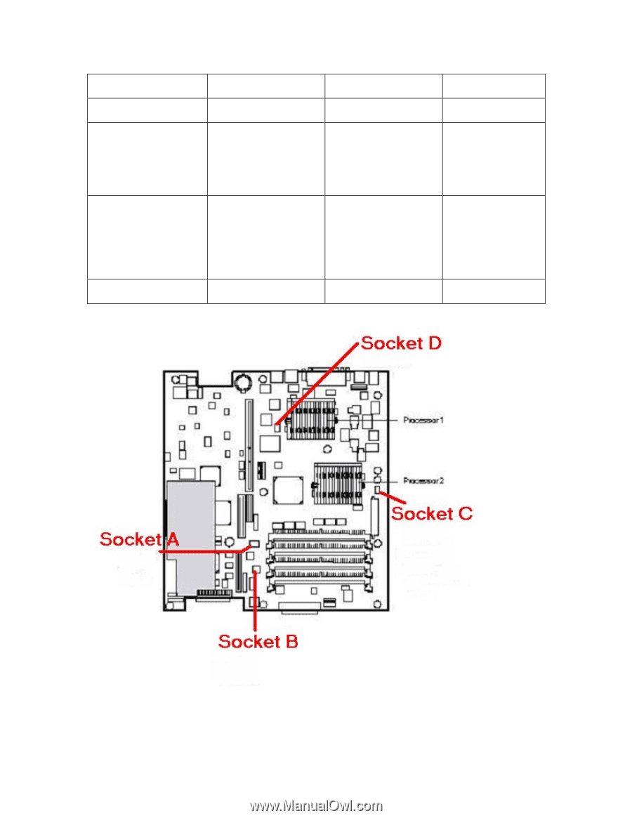
- HP LH4r | LP2000r Fan Connector Diagram - Page 1
2 CPU Fan 2, Fan Connector C floppy drive) CPU Fan. (see figure below) This fan and system Fan Connector D **(see figure below) ** This fan socket is not labeled on the system board. DO NOT use this connector. It will provide power to the fan, but this connector is not monitored, so if a fan
-
 1
1
 |
 |
Physical Fan
System Board Connector
Silkscreen
Event Log Notation
Fan and Connector
Photo
Fan that cools the PCI
cage
CHA_Fan 1
Chassis Fan 1,
Fan Connector A (see
figure below)
Front (closest to the
floppy drive) CPU fan
(This is the only CPU fan
in LP2000r systems with
866 MHz, 933 MHz and
1 GHz processors)
CHA_Fan 2
Chassis Fan 2
Fan Connector B
(see figure below)
Rear (Furthest from the
floppy drive) CPU Fan.
This fan and system
board socket should only
be installed in LP2000r
units with 1.13, 1.26 or
1.40 GHz CPU's
CPU_Fan 2
CPU Fan 2,
Fan Connector C
(see figure below)
**None
No label for connector
Not monitored
Fan Connector D
**(see figure below)
** This fan socket is not labeled on the system board.
DO NOT use this connector.
It will provide power
to the fan, but this connector is not monitored, so if a fan failure occurs no errors will be generated.