HP LH4r HP Netserver LH 3000 Technical Reference Card
HP LH4r - NetServer - 256 MB RAM Manual
 |
View all HP LH4r manuals
Add to My Manuals
Save this manual to your list of manuals |
HP LH4r manual content summary:
- HP LH4r | HP Netserver LH 3000 Technical Reference Card - Page 1
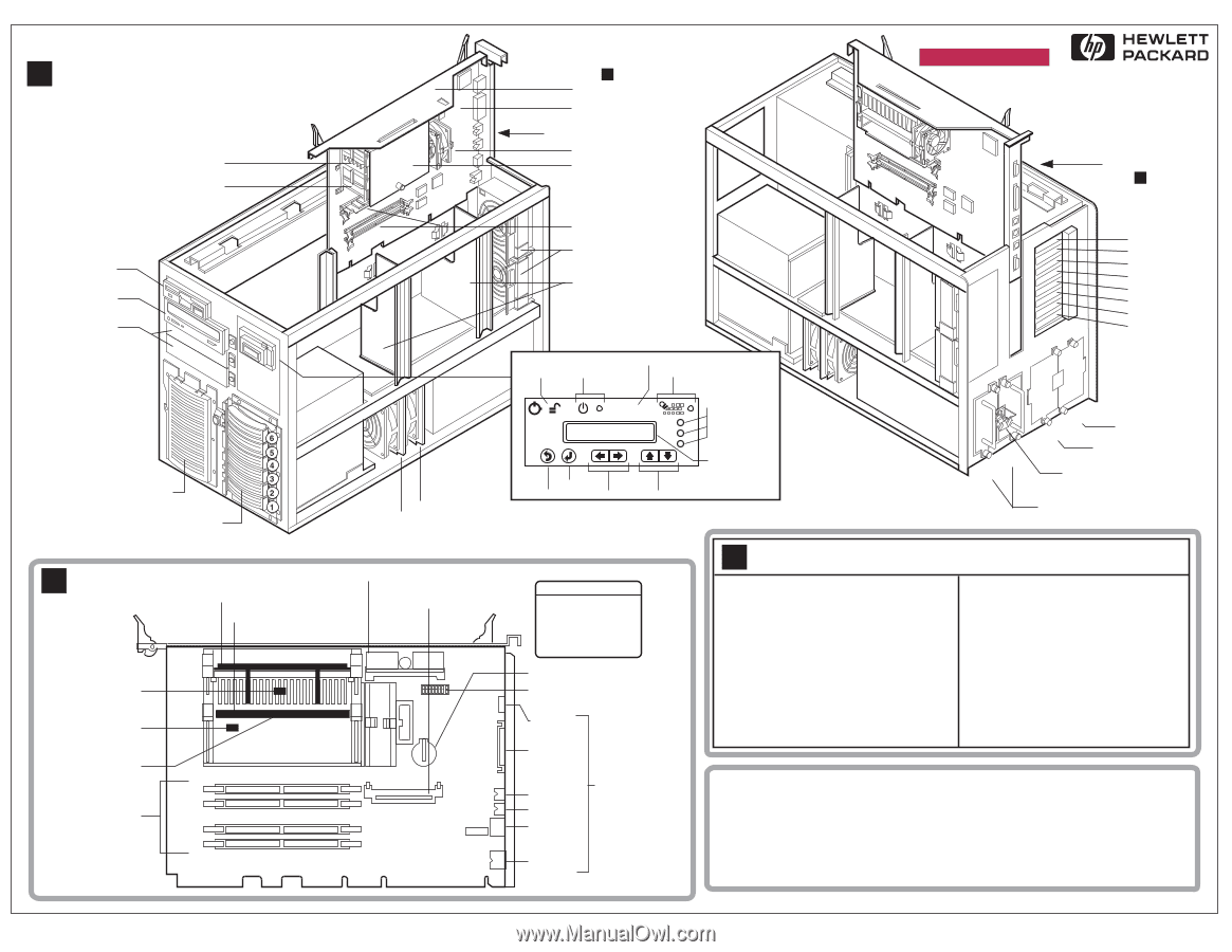
Fans: Reset Server Status LEDs Select Drive 2. Flexible Disk Drive 3. Embedded SCSI 4. Other SCSI Device (Settable) CMOS Battery Configuration Switches Serial Parallel Mouse Keyboard LAN I/O Connectors Video C Quick Reference Note: See HP NetServer LH 3000/3000r Installation Guide service - HP LH4r | HP Netserver LH 3000 Technical Reference Card - Page 2
HP NetServer LH 3000/3000r D Cabling: Data Front Panel Display Cable P/O Display Flexible Disk Drive IDE CD-ROM NonHot 32 or 64 Bit Remote Management OLx Connector Non-Hot-Plug Slots (1 - 4) I/O Memory (for NetRAID Cache) SE SCSI Connector I/O Fan (Removed) 1 2 3 Location of 4 OLx Board 5
-
 1
1 -
 2
2
 |
 |
Cabinet
A
HP NetServer LH 3000/3000r
For additional information, see other side.
Caution: DO NOT operate server for more than
60 minutes with any cover (including Power
Supply and Disk Drive) removed. Over-
temperature may cause component damage.
1
2
3
4
5
6
7
8
I/O Connectors
See
Power Supplies
Unused
PCI Slots:
Optional Redundant
Power Supply Slot
Power Supply Connector
and Strain-Relief
4
3
2
1
B
D8228-80201, Rev A
Board Stiffener
Power
Supply
Fans:
Pair
A
Pair
B
Air Baffles
Exhaust Fans
Primary
Processor
Processor Cage
Cover
Processor Fan
I/O Connectors
Secondary
Processor Slot
(Terminator in Place)
Shelf 1:
Flexible Disk Drive
Shelf 2:
CD-ROM
Shelves 3 & 4:
Optional Mass
Storage Devices
Hot-Swap Mass Storage:
Secondary Cage
(Optional)
Primary Slots (1- 6 )
System Board
DIMM Slots
System Board Assembly
See
:
B
Reset
Power
and Indicator
Lock
Server Status
LEDs
Back
Select
Scr
oll 2-Line Display
2-Line Display
Not Used
Reset (located under cover)
Keyboard Lock
and Indicator
Front Panel Console
Non-Hot-Swap
Shelves:
BARCODE AREA
System Board Assembly
B
DIMM Memory
Sockets
Terminator
Temperature
Sensors:
Serial
Parallel
Mouse
LAN
Keyboard
Video
Primary Processor
Primary (U18)
(Under Processor)
Secondary (U17)
Secondary Processor
Slot (Upgrade)
Primary Voltage Regulator
Module (VRM)
Secondary VRM
Slot
Configuration
Switches
2
3
0
1
CMOS Battery
Boot Order
Default Boot Order
IDE CD-ROM Drive
Flexible Disk Drive
Embedded SCSI
Other SCSI Device
(Settable)
1.
2.
3.
4.
Audience Assumptions
This Technical Reference Card is for trained
service personnel. Hewlett-Packard Company
assumes you are qualified in the servicing of
computer equipment and trained in recognizing
hazards in products with hazardous energy
levels.
Electrostatic Discharge
To avoid catastrophic or hidden damage to
components, wear a wrist strap and use a static-
dissipative work surface connected to the chassis
when handling components.
Use an antistatic
service kit, such as 3M
®
8501/8502/8505 or
equivalent.
This information is subject to change without
notice and is provided without warranty.
© Copyright 1999 Hewlett-Packard Company
I/O Connectors
DIMM Installation
LED Interpretation
Note: See
HP NetServer LH 3000/3000r
Installation Guide
Off
= No Power, or Normal
Green Solid
= Normal, or Power On
Green Flashing
= Normal Activity
Only Green Flashing (RJ-45)
= 10 Mbps
Amber (HDD)
= Failure Predicted
Yellow Flashing
= Pre Failure Condition
Amber (PCI Slot)
= Slot Needs Attention
Yellow (RJ-45)
= LAN is 100 Mbps
Red Solid
= 12 V Failure
Red Flashing
= Failure, Immediate Attention
Quick Reference
C
Use up to 4 HP SDRAM DIMMs in sizes
of 128MB, 256MB, 512MB, and 1GB.
•
First DIMM is supplied in Slot 0.
•
You can add DIMMs to Slots 1, 2, or 3
in any order.
•
Maximum system size is 4GB.
•
You can insert any approved size DIMM
in any DIMM slot.
•