HP LH4r HP Netserver LH 4 and LH 4r Tech Reference Card
HP LH4r - NetServer - 256 MB RAM Manual
 |
View all HP LH4r manuals
Add to My Manuals
Save this manual to your list of manuals |
HP LH4r manual content summary:
- HP LH4r | HP Netserver LH 4 and LH 4r Tech Reference Card - Page 1
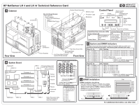
HP NetServer LH 4 and LH 4r Technical Reference Card A Cabinet I/O Connectors Non-Hot-Swap Shelves: Shelf 4 (empty) Shelf 3 (empty) Shelf 2 (CD-ROM Drive) Shelf 1 (Flexible Disk Drive Display Hard Disk Drive Indicator DIMM is not installed; uncorrectable error; or inappropriate DIMM Processor 2 - HP LH4r | HP Netserver LH 4 and LH 4r Tech Reference Card - Page 2
avoid configuration problems, install hot-swap drives in consecutive Drive Spacer H Service Information Electronic Support Services • Internet Web Page http://www.hp.com/go/netserver • Internet FTP ftp://ftp.hp.com/pub/servers • CompuServe Library GO HPPC • HP Navigator CD Support Questions • HP
-
 1
1 -
 2
2
 |
 |
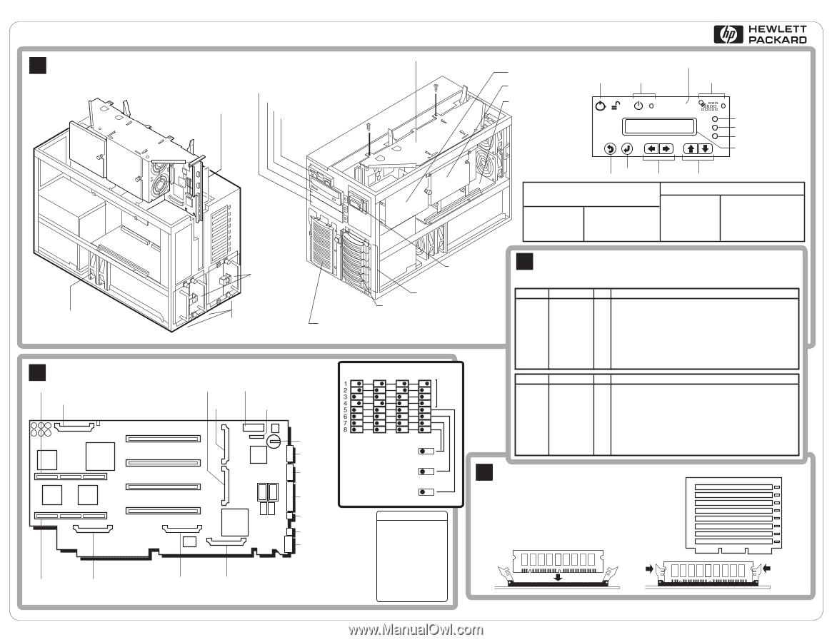
Cabinet
A
HP NetServer LH 4 and LH 4r Technical Reference Card
System Board
B
Note: Processor slots
without Processors
have terminators.
1.
2.
3.
4.
5.
6.
7.
8.
9.
Boot Order
IDE CD-ROM
Floppy Drive
Embedded SCSI
PCI 6
PCI 5
PCI 4
PCI 3
PCI 2
PCI 1
1.
2.
3.
4.
5.
6.
7.
8.
9.
10.
11.
Default Boot Order
IDE CD-ROM Drive
Flexible Disk Drive
Embedded SCSI
PCI 8
PCI 7
PCI 6
PCI 5
PCI 4
PCI 3
PCI 2
ISA / PCI 1
Rear View
Front View
DIMM Installation Guidelines
Use EDO buffered TSOP 64 or 256Mb 50ns DIMMs.
•
Install four matching DIMMs at a time (two DIMMs on
Memory Card A and two DIMMs on Memory Card B).
•
DIMMs are Four Way Interleaved.
•
Install from DIMM Socket 1 to 8.
•
The LEDs will provide key information about the system when any of the core
processors cannot fetch the BIOS.
The following table indicates LED usage.
For additional information, see other side.
2
1
Control Panel
DIMM Installation
D
Reset (located
under panel)
Power
and Indicator
Lock
Keyboard Lock
and Indicator
Green
Yellow
Red
Status LEDs:
Back
Select
Scroll 2-Line Display
Reset
2-Line Display
Not Used
Monitor
Serial B
Serial A
Parallel
Mouse
Keyboard
VRM 1
VRM 2
VRM 4
VRM 3
Processor Speed and
System DIP Switches
External Battery
Battery
VRM 1/2
VRM 3/4
Processor 4
Processor 3
Processor 2
Processor 1
Memory A
Memory B
ON
OFF
400
ON
OFF
450
ON
OFF
500
100 MHz FSB
Test Only (7 & 8)
Password (6)
Clear Password
Config. Memory (5)
Clear Config. (CMOS)
CPU
Speed
ON
OFF
550
*
*
*
*
*
*
*
*
*
DIMM is not installed; uncorrectable
error; or inappropriate DIMM
Mem A
On
LED 1
Off
Flashing
LED 2
LED 3
LED 4
LED 5
LED 6
LED 7
LED 8
DIMM 1 ok
DIMM 2 ok
DIMM 3 ok
DIMM 4 ok
DIMM 5 ok
DIMM 6 ok
DIMM 7 ok
DIMM 8 ok
Processor 1 Slot: Critical Error, Thermal Trip, or Empty
Processor 2 Slot: Critical Error, Thermal Trip, or Empty
Processor 3 Slot: Critical Error, Thermal Trip, or Empty
Processor 4 Slot: Critical Error, Thermal Trip, or Empty
System voltage issue
Processor temperature over limit
System and DIMM Indicators
C
*
*
*
*
*
*
*
*
*
DIMM is not installed; uncorrectable
error; or inappropriate DIMM
Mem B
On
LED 1
Off
Flashing
LED 2
LED 3
LED 4
LED 5
LED 6
LED 7
LED 8
DIMM 1 ok
DIMM 2 ok
DIMM 3 ok
DIMM 4 ok
DIMM 5 ok
DIMM 6 ok
DIMM 7 ok
DIMM 8 ok
VRM 1 not installed or bad
VRM 2 not installed or bad
VRM 3 not installed or bad
VRM 4 not installed or bad
VRM 1/2 not installed or bad
VRM 3/4 not installed or bad
J1
J2
J3
J4
J5
J6
J7
J8
TOP
LED 1
LED 2
LED 3
LED 4
LED 5
LED 6
LED 7
LED 8
Hard Disk Drive Indicator LEDs
Flashing
Green
Accessing disk.
Steady
Green
Disk spinning or "hung."
Flashing
Amber
Disk failure predicted.
Steady
Red
Disk failed.
Off
No disk activity.
Activity Status LED
Disk not present or
not connected to
cage.
Off
Steady
Green
Disk present.
Power Status LED
Memory Cage
Shelf 1
(Flexible Disk Drive)
Shelf 2 (CD-ROM Drive)
Shelf 3 (empty)
Shelf 4 (empty)
Non-Hot-Swap Shelves:
Hard Disk Drive LEDs
Hot-Swap Mass Storage
Expansion Bay (empty)
Control Panel
System Board Assembly
Backplane
Processor Cage
Hot-Swap Mass
Storage Cage
Power
Connectors
I/O
Connectors
Power Supplies
Redundant Fan