HP Mellanox SX1018 Mellanox SX1018HP Ethernet Switch Installation Instructions
HP Mellanox SX1018 Manual
 |
View all HP Mellanox SX1018 manuals
Add to My Manuals
Save this manual to your list of manuals |
HP Mellanox SX1018 manual content summary:
- HP Mellanox SX1018 | Mellanox SX1018HP Ethernet Switch Installation Instructions - Page 1
setup and installation guide or HP BladeSystem enclosure installation poster. Programming and provisioning manuals To access the most current versions of the Mellanox SX1018HP Ethernet Switch programming and provisioning manuals, enter the model name or the HP part number in the Support and Drivers - HP Mellanox SX1018 | Mellanox SX1018HP Ethernet Switch Installation Instructions - Page 2
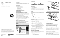
Hewlett-Packard Development Company, L.P HP 720989-022 2013年4 2 概要 Mellanox SX1018HP Ethernet HP BladeSystem c-Class Mellanox SX1018HP Ethernet HP BladeSystem c-Classエ 1 追加情報 HP BladeSystem Mellanox SX1018HP Ethernet Support and Drivers HPのWebサイトhttp://www.hp.com/go
-
 1
1 -
 2
2
 |
 |
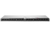
Mellanox SX1018HP Ethernet
Switch
Installation Instructions
for HP BladeSystem c-Class enclosures
Overview
This card provides instructions for installing the Mellanox SX1018HP
Ethernet Switch in an HP BladeSystem c-Class enclosure.
Kit contents
The kit includes the following items:
•
One Mellanox SX1018HP Ethernet Switch for the HP
BladeSystem c-Class enclosure
•
This installation card
•
Warranty documentation
Additional information
Mezzanine card installation
Mezzanine card installation determines bay assignments for
interconnect module installation. For more information on the
association between the mezzanine connector and the interconnect
bays, see the HP BladeSystem enclosure setup and installation guide
or HP BladeSystem enclosure installation poster.
Programming and provisioning manuals
To access the most current versions of the Mellanox SX1018HP
Ethernet Switch programming and provisioning manuals, enter the
model name or the HP part number in the Support and Drivers section
of the HP website (http://www.hp.com/go/bizsupport).
Port assignments
For specific port connections for each server blade, see the
HP
BladeSystem Onboard Administrator User Guide
.
The following Onboard Administrator screen example provides a
reference for port mapping. Your screen might differ slightly
depending on the HP Ethernet switch you are using.
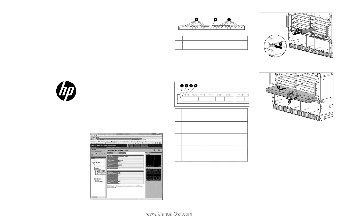
Connectors
Item
Description
1
QSFP+ uplink ports (18)
2
Debug port
See the HP BladeSystem enclosure setup and installation guide for
more information on the BladeSystem port mapping.
LEDs
The following LED layout and table describe the Mellanox SX1018HP
Ethernet Switch LED behavior that is expected during setup and
operation.
Item Description
Status
1
Unit ID LED
Blue = Activated
Off = Deactivated
2
Internal health
LED
Green = Normal
Amber = Component degraded
Off = Power off
3
Physical link LED Green = Physical link established
Green flashing = Physical link error
Off = No physical link established
4
Logical
link/activity LED
Amber = Logical link established
Amber flashing = Logical link with
activity*
Off = No logical link established
*The logical link-activity LED flashes with greater frequency as
network activity increases.
Installing the module
The Mellanox SX1018HP Ethernet Switch is a double-wide enclosure
that occupies two adjacent interconnect bays.
To install the module:
1.
Prepare the bay:
a.
Remove any devices or blanks.
b.
Remove the divider.
2.
Install the Mellanox SX1018HP Ethernet Switch, and then close
the release lever.
The installation is complete.
Translated version
For translated instructions in Japanese, see the documentation
provided on the HP website
Safety and regulatory compliance
For safety, environmental, and regulatory information, see
Safety and
Compliance Information for Server, Storage, Power, Networking, and
Rack Products
, available at the HP website
Documentation feedback
HP is committed to providing documentation that meets your needs. To
help us improve the documentation, send any errors, suggestions, or
comments to Documentation Feedback
(mailto:[email protected]). Include the document title and part
number, version number, or the URL when submitting your feedback.
© Copyright 2013 Hewlett-Packard Development Company, L.P.
The information contained herein is subject to change without notice. The only
warranties for HP products and services are set forth in the express warranty
statements accompanying such products and services. Nothing herein should
be construed as constituting an additional warranty. HP shall not be liable for
technical or editorial errors or omissions contained herein.
Part Number: 720989-022
April 2013
Edition: 2
*720989-022*
720989-022