HP Mini 110-3710ca HP Mini 110 and Compaq Mini CQ10 - Maintenance and Service
HP Mini 110-3710ca Manual
 |
View all HP Mini 110-3710ca manuals
Add to My Manuals
Save this manual to your list of manuals |
HP Mini 110-3710ca manual content summary:
- HP Mini 110-3710ca | HP Mini 110 and Compaq Mini CQ10 - Maintenance and Service - Page 1
HP Mini 110 Compaq Mini CQ10 Maintenance and Service Guide - HP Mini 110-3710ca | HP Mini 110 and Compaq Mini CQ10 - Maintenance and Service - Page 2
Atom are trademarks of Intel Corporation in the U.S. and other countries. Windows is a U.S. registered trademark of Microsoft Corporation. SD Logo is a trademark of its proprietor. The information contained herein is subject to change without notice. The only warranties for HP products and services - HP Mini 110-3710ca | HP Mini 110 and Compaq Mini CQ10 - Maintenance and Service - Page 3
Safety warning notice WARNING! To reduce the possibility of heat-related injuries or of overheating the device, do not place the device directly on your lap or obstruct the device air vents. Use the device only on a hard, flat surface. Do not allow another hard surface, such as an adjoining optional - HP Mini 110-3710ca | HP Mini 110 and Compaq Mini CQ10 - Maintenance and Service - Page 4
iv Safety warning notice - HP Mini 110-3710ca | HP Mini 110 and Compaq Mini CQ10 - Maintenance and Service - Page 5
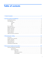
...10 Display components ...12 Bottom components ...13 Wireless antennas ...14 Additional hardware components 15 3 Illustrated parts catalog 16 Service tag ...16 Computer major components 17 Display components ...23 Mass storage device ...25 Miscellaneous parts ...26 Sequential part number - HP Mini 110-3710ca | HP Mini 110 and Compaq Mini CQ10 - Maintenance and Service - Page 6
replacement procedures 39 Computer feet ...39 Battery ...40 SIM ...42 Service access cover 43 Hard drive ...45 WWAN and GPS modules ( ...58 Display assembly ...61 Fan/heat sink assembly 69 System board ...71 Power connector cable 75 5 Setup Utility ...77 Starting Setup Utility ...77 Using Setup - HP Mini 110-3710ca | HP Mini 110 and Compaq Mini CQ10 - Maintenance and Service - Page 7
restore points 89 When to create restore points 89 Create a system restore point 89 Restore to a previous date and time 89 8 Power cord set requirements 90 Requirements for all countries 90 Requirements for specific countries and regions 91 9 Recycling ...92 Battery ...92 Display ...92 Index - HP Mini 110-3710ca | HP Mini 110 and Compaq Mini CQ10 - Maintenance and Service - Page 8
viii - HP Mini 110-3710ca | HP Mini 110 and Compaq Mini CQ10 - Maintenance and Service - Page 9
name HP Mini 110 Netbook PC √ Compaq Mini CQ10 Netbook PC Processor Intel® Atom™ N570 1.66-GHz processor (dual core, 1-MB level √ 2 cache, 667-MHz front-side bus (FSB), 8.5 W) Intel Atom N475 1.83-GHz processor (single core, 512-KB level 2 cache, 667-MHz FSB, 6.5 W) Intel Atom N455 1.66 - HP Mini 110-3710ca | HP Mini 110 and Compaq Mini CQ10 - Maintenance and Service - Page 10
only HD audio √ √ √ √ Integrated 1.5-W speakers (2) Fixed integrated, digital microphone Fixed integrated VGA webcam, 640×480 resolution, F/2.8 lens, up to 30 frames per second Modem Supports external USB modems only √ √ Ethernet Integrated Realtek RTL8105EL 10/100 network interface - HP Mini 110-3710ca | HP Mini 110 and Compaq Mini CQ10 - Maintenance and Service - Page 11
Module ● HP lc 2010 Mobile Broadband Module (select models only) √ √ 2 WWAN antennas built into display assembly (select models √ √ only) GPS by way of Broadcom GPS Mini Card (select models only) External media cards Digital Media Slot with push-push technology, supporting: ● Memory - HP Mini 110-3710ca | HP Mini 110 and Compaq Mini CQ10 - Maintenance and Service - Page 12
ft) power cord 3-cell Lithium-ion (Li-ion) battery (2.55-Ahr, 28-Wh) Security Operating system 6-cell Li-ion high-capacity battery (2.55-Ahr, 55-Wh) Kensington lock slot Windows 7 Starter Windows 7 Professional (select countries) √ √ √ √ Support for HP QuickWeb USB Key Recovery support (for - HP Mini 110-3710ca | HP Mini 110 and Compaq Mini CQ10 - Maintenance and Service - Page 13
2 External component identification Identifying the hardware Components included with the computer may vary by country or region and by model. The illustrations in this chapter identify the standard features on most computer models. To see a list of hardware installed in the computer, follow these - HP Mini 110-3710ca | HP Mini 110 and Compaq Mini CQ10 - Maintenance and Service - Page 14
Top components TouchPad Component Description (1) TouchPad zone Moves the pointer and selects or activates items on the screen. (2) TouchPad button* Functions like the left and right buttons on an external mouse. *This table describes factory settings. To view or change pointing device - HP Mini 110-3710ca | HP Mini 110 and Compaq Mini CQ10 - Maintenance and Service - Page 15
Lights Component (1) Caps lock light (2) Mute light (3) Wireless light Description ● White: Caps lock is on. ● Off: Caps lock is off. ● Amber: Computer sound is off. ● Off: Computer sound is on. ● White: An integrated wireless device, such as a wireless local area network (WLAN) device and/or - HP Mini 110-3710ca | HP Mini 110 and Compaq Mini CQ10 - Maintenance and Service - Page 16
Keys Component (1) esc key (2) fn key (3) Windows® logo key (4) Windows applications key (5) Action keys Front components Component Speakers (2) Description Displays system information when pressed in combination with the fn key. Displays information about system hardware components and - HP Mini 110-3710ca | HP Mini 110 and Compaq Mini CQ10 - Maintenance and Service - Page 17
Right-side components Component (1) Digital Media Slot (2) Power light (3) Power switch (4) USB ports (2) Description Supports the following optional digital card formats: ● Memory Stick ● Memory Stick Pro ● MultiMediaCard ● Secure Digital (SD) Card ● Secure Digital High Capacity (SDHC) - HP Mini 110-3710ca | HP Mini 110 and Compaq Mini CQ10 - Maintenance and Service - Page 18
reaches a critical battery level, the battery light begins blinking rapidly. ● Amber: A battery is charging. ● White: The computer is connected to external power and the battery is fully charged. Connects an external VGA monitor or projector. Enables airflow to cool internal components. NOTE: The - HP Mini 110-3710ca | HP Mini 110 and Compaq Mini CQ10 - Maintenance and Service - Page 19
Audio-out (headphone) jack/Audio-in (microphone) jack Description Connects an optional USB device. Produces sound when connected to optional powered stereo speakers, headphones, earbuds, a headset, or television audio. Also connects an optional headset microphone. WARNING! To reduce the risk of - HP Mini 110-3710ca | HP Mini 110 and Compaq Mini CQ10 - Maintenance and Service - Page 20
Display components Component (1) Internal display switch (2) Internal microphone (3) Webcam (4) Webcam light Description Initiates Sleep if the display is closed while the power is on. NOTE: The display switch is not visible from the outside of the computer. Records sound. Records video and - HP Mini 110-3710ca | HP Mini 110 and Compaq Mini CQ10 - Maintenance and Service - Page 21
Bottom components Component (1) Battery locking latch (2) Battery bay (3) Battery release latch Description Locks the battery into the battery bay. Holds the battery. NOTE: The SIM slot is located under the battery. Releases the battery from the battery bay. Bottom components 13 - HP Mini 110-3710ca | HP Mini 110 and Compaq Mini CQ10 - Maintenance and Service - Page 22
, refer to the section of the Regulatory, Safety and Environmental Notices that applies to your country or region. These notices are located in Help and Support. 14 Chapter 2 External component identification - HP Mini 110-3710ca | HP Mini 110 and Compaq Mini CQ10 - Maintenance and Service - Page 23
hardware components Component Description (1) Power cord* Connects an AC adapter to an AC outlet. (2) AC adapter Converts AC power to DC power. (3) Battery* Powers the computer when the computer is not plugged into external power. *Batteries and power cords vary in appearance by region - HP Mini 110-3710ca | HP Mini 110 and Compaq Mini CQ10 - Maintenance and Service - Page 24
When ordering parts or requesting information, provide the computer serial number and model description provided on the service tag. Component (1) Product name (2) Serial number (s/n) (3) Part number/Product number (p/n) (4) Warranty period (5) Model description 16 Chapter 3 Illustrated - HP Mini 110-3710ca | HP Mini 110 and Compaq Mini CQ10 - Maintenance and Service - Page 25
Computer major components Computer major components 17 - HP Mini 110-3710ca | HP Mini 110 and Compaq Mini CQ10 - Maintenance and Service - Page 26
cable, 2 WLAN transceivers and cables, 2 WWAN transceivers and cables (select models only), and webcam/microphone module and cable): WSVGA, AntiGlare, LED display assembly in black for use only on Compaq Mini CQ10 LTE 638150-001 computer models WSVGA, AntiGlare, LED display assembly in black for - HP Mini 110-3710ca | HP Mini 110 and Compaq Mini CQ10 - Maintenance and Service - Page 27
Item Description Spare part number For use in Thailand 647569-281 For use in Turkey 647569-141 For use in the United Kingdom and Singapore 647569-031 For use in the United States 647569-001 For use with computer models with model numbers 3500 through 3599 or 3600 through 3699: For use in - HP Mini 110-3710ca | HP Mini 110 and Compaq Mini CQ10 - Maintenance and Service - Page 28
, 667-MHz FSB, 6.5 W) and WWAN capability, for use with computer models with model numbers 3700 through 3799 659028-001 Equipped with an Intel Atom N455 1.66-GHz processor (single core, 512-KB level 2 cache, 659026-001 667-MHz FSB, 6.5 W) but not WWAN capability, for use with computer models with - HP Mini 110-3710ca | HP Mini 110 and Compaq Mini CQ10 - Maintenance and Service - Page 29
capability, for use with Compaq Mini CQ10 LTE computer models with model numbers 3700 through 3799 642158-001 Equipped with an Intel Atom N455 1.66-GHz processor (single core, 512-KB 621563-001 2-GB 621567-001 (10) Power connector cable 622329-001 (11) WWAN module (select models only) - HP Mini 110-3710ca | HP Mini 110 and Compaq Mini CQ10 - Maintenance and Service - Page 30
HP lc 2010 Mobile Broadband Module (HP Mini 110/Compaq Mini CQ10 models only) HP lc 2000 Mobile Broadband Module HP lt 2510 EV-DO/LTE Mobile Broadband Module HP (16) Service access cover Black (for use in all countries and regions except Brazil) Black (for use only in Brazil) Power connector bracket - HP Mini 110-3710ca | HP Mini 110 and Compaq Mini CQ10 - Maintenance and Service - Page 31
covers Left and right hinge caps Left and right hinge cap wall Display Hinge Kit (includes right and left hinges) For use with HP Mini 110 and Compaq Mini CQ10 computer models For use with Compaq Mini CQ10 LTE computer models Spare part number 633483-001 633482-001 638232-001 Display components 23 - HP Mini 110-3710ca | HP Mini 110 and Compaq Mini CQ10 - Maintenance and Service - Page 32
models 638231-001 For use with Compaq Mini CQ10 computer models 633489-001 For use with HP Mini 110 computer models 633493-001 Webcam module 631703-001 Display panel: 10.1-in, WSVGA, AntiGlare display panel for use with HP Mini 110 and Compaq Mini CQ10 computer models 624218-001 10.1-in - HP Mini 110-3710ca | HP Mini 110 and Compaq Mini CQ10 - Maintenance and Service - Page 33
Mass storage device Description Hard drive (does not include bracket, cover, or screws): 500-GB, 7200-rpm, 7.0-mm 320-GB, 7200-rpm, 7.0-mm 320-GB, 5400-rpm, 7.0-mm 250-GB, 7200-rpm, 7.0-mm 250-GB, 5400-rpm, 7.0-mm 160-GB, 7200-rpm, 7.0-mm Hard Drive Hardware Kit (not illustrated; includes bracket, - HP Mini 110-3710ca | HP Mini 110 and Compaq Mini CQ10 - Maintenance and Service - Page 34
Miscellaneous parts Description AC adapter (40-W, non-smart RC/V 2W) HP wireless optical mouse Black mini-sleeve Power cord: For use in Argentina For use in Australia For use in Brazil For use in Denmark For use in Europe For use in India For - HP Mini 110-3710ca | HP Mini 110 and Compaq Mini CQ10 - Maintenance and Service - Page 35
Power cord for use in Israel Power cord for use in Argentina Power cord for use in India Qualcomm Gobi 2000 3G WWAN module (select models only) External DVD±RW and CD-RW Super Multi Double-Layer Combo Drive with LightScribe Black mini-sleeve Broadcom 4313/2070 802.11b/g/n (1×1) WiFi Mini Card HP - HP Mini 110-3710ca | HP Mini 110 and Compaq Mini CQ10 - Maintenance and Service - Page 36
panel for use with HP Mini 110 and Compaq Mini CQ10 computer models 40-W AC adapter, non-Smart RC/V 2W Hard Drive Cable Kit 3-cell Li-ion battery (28-WH 2.55-Ahr) 6-cell Li-ion high-capacity battery (55-WH 2.5-Ahr) System board equipped with an Intel Atom N455 1.66-GHz processor (single core, 512-KB - HP Mini 110-3710ca | HP Mini 110 and Compaq Mini CQ10 - Maintenance and Service - Page 37
for use with computer models with model numbers 3500 through 3599 or 3600 through 3699 in Greece (includes cable) Display enclosure for use in black HP-branded models Display enclosure for use in white HP-branded models Sequential part number listing 29 - HP Mini 110-3710ca | HP Mini 110 and Compaq Mini CQ10 - Maintenance and Service - Page 38
use with HP Mini 110 and Compaq Mini CQ10 computer models Hard Drive Hardware Kit (includes bracket, cover, and screws) Display enclosure for use in black Compaq-branded models Display bezel for use in HP-branded models System board equipped with an Intel Atom N455 1.66-GHz processor (single core - HP Mini 110-3710ca | HP Mini 110 and Compaq Mini CQ10 - Maintenance and Service - Page 39
(select models only), and webcam/microphone module and cable) HP lt 2510 EV-DO/LTE Mobile Broadband Module Power connector bracket 500-GB, 7200-rpm, 7.0-mm hard drive (does not include bracket, cover, or screws) System board equipped with an Intel Atom N455 1.66-GHz processor (single core, 512-KB - HP Mini 110-3710ca | HP Mini 110 and Compaq Mini CQ10 - Maintenance and Service - Page 40
Spare part number 647569-031 647569-041 647569-051 647569-061 647569-071 647569-121 647569-131 647569-141 647569-161 647569-171 647569-211 647569-221 647569-251 647569-281 647569-291 647569-A41 647569-AB1 647569-AD1 647569-B31 647569-BA1 Description Keyboard for use with computer models with model - HP Mini 110-3710ca | HP Mini 110 and Compaq Mini CQ10 - Maintenance and Service - Page 41
Kit for use with 7.0-mm hard drives (includes bracket, cover, and screws) Display/webcam cable for use with Compaq Mini CQ10 LTE computer models System board equipped with an Intel Atom N455 1.66-GHz processor (single core, 512-KB level 2 cache, 667-MHz FSB, 6.5 W), high-definition video, but - HP Mini 110-3710ca | HP Mini 110 and Compaq Mini CQ10 - Maintenance and Service - Page 42
● Flat-bladed screwdriver ● Magnetic screwdriver ● Phillips P0 and P1 screwdrivers Service considerations The following sections include some of the considerations that you must keep only at the points designated in the maintenance instructions. 34 Chapter 4 Removal and replacement procedures - HP Mini 110-3710ca | HP Mini 110 and Compaq Mini CQ10 - Maintenance and Service - Page 43
Cables and connectors CAUTION: When servicing the device, be sure that cables are placed in their proper locations during the reassembly process. Improper cable placement can damage the device. Cables must - HP Mini 110-3710ca | HP Mini 110 and Compaq Mini CQ10 - Maintenance and Service - Page 44
determine the degree of sensitivity. Networks built into many integrated circuits provide some protection, but in many cases, ESD contains enough power to alter device parameters or melt silicon junctions. A discharge of static electricity from a finger or other conductor can destroy static - HP Mini 110-3710ca | HP Mini 110 and Compaq Mini CQ10 - Maintenance and Service - Page 45
surface and use properly grounded tools and equipment. ● Use conductive field service tools, such as cutters, screwdrivers, and vacuums. ● When fixtures must with pins, leads, or circuitry. ● Turn off power and input signals before inserting or removing connectors or test equipment. Preliminary - HP Mini 110-3710ca | HP Mini 110 and Compaq Mini CQ10 - Maintenance and Service - Page 46
mat. Foot straps (heel, toe, or boot straps) can be used at standing workstations and are compatible with most types of shoes or boots. On conductive floors or dissipative floor mats cords of one megohm resistance ● Static-dissipative tables or floor mats with hard ties to the ground ● Field service - HP Mini 110-3710ca | HP Mini 110 and Compaq Mini CQ10 - Maintenance and Service - Page 47
removal and replacement procedures. There are as many as 33 screws, in 5 different sizes, that must be removed, replaced, or loosened when servicing the computer. Make special note of each screw size and location during removal and replacement. Computer feet The computer feet are adhesive-backed - HP Mini 110-3710ca | HP Mini 110 and Compaq Mini CQ10 - Maintenance and Service - Page 48
-001 Remove the battery: CAUTION: Removing a battery that is the sole power source for the computer can cause loss of information. To prevent loss of Disconnect all external devices connected to the computer. 3. Unplug the power cord from the AC outlet. 4. With the display closed, position the - HP Mini 110-3710ca | HP Mini 110 and Compaq Mini CQ10 - Maintenance and Service - Page 49
2. Slide the battery locking latch (3) to the right to lock the battery into the battery bay. Component replacement procedures 41 - HP Mini 110-3710ca | HP Mini 110 and Compaq Mini CQ10 - Maintenance and Service - Page 50
then shut it down through the operating system. 2. Disconnect all external devices connected to the computer. 3. Disconnect the power from the computer by first unplugging the power cord from the AC outlet and then unplugging the AC adapter from the computer. 4. Remove the battery (see Battery on - HP Mini 110-3710ca | HP Mini 110 and Compaq Mini CQ10 - Maintenance and Service - Page 51
from the computer by first unplugging the power cord from the AC outlet and then unplugging the AC adapter from the computer. 4. Remove the battery (see Battery on page 40). Remove the service access cover: 1. Slide the service access cover release lever (1) to the right. 2. Lift up the edge (2) of - HP Mini 110-3710ca | HP Mini 110 and Compaq Mini CQ10 - Maintenance and Service - Page 52
2. Insert the tabs into the slots (2), and swing the cover (3) down. 3. Press down firmly on the cover until it clicks into place. 44 Chapter 4 Removal and replacement procedures - HP Mini 110-3710ca | HP Mini 110 and Compaq Mini CQ10 - Maintenance and Service - Page 53
to the computer. 3. Disconnect the power from the computer by first unplugging the power cord from the AC outlet and then unplugging the AC adapter from the computer. 4. Remove the following components: a. Battery (see Battery on page 40). b. Service access cover (see Service access cover on page 43 - HP Mini 110-3710ca | HP Mini 110 and Compaq Mini CQ10 - Maintenance and Service - Page 54
5. Use the tab (5) to remove the hard drive from the computer. 6. If it is necessary to replace the hard drive bracket, connector cable, cover, or screws, follow these steps: a. Disconnect the hard drive connector cable from the hard drive. b. Remove the four Phillips 3.0×3.0 screws (1) that secure - HP Mini 110-3710ca | HP Mini 110 and Compaq Mini CQ10 - Maintenance and Service - Page 55
d. Remove the hard drive cover (3). Reverse this procedure to reassemble and install the hard drive. Component replacement procedures 47 - HP Mini 110-3710ca | HP Mini 110 and Compaq Mini CQ10 - Maintenance and Service - Page 56
are very similar. Either can populate the WWAN slot. Description HP lc 2010 Mobile Broadband Module (HP Mini 110/Compaq Mini CQ10 models only) HP lc 2000 Mobile Broadband Module HP lt 2510 EV-DO/LTE Mobile Broadband Module HP td2500 TD-SCDMA Mobile Broadband Module Qualcomm Gobi 2000 3G module - HP Mini 110-3710ca | HP Mini 110 and Compaq Mini CQ10 - Maintenance and Service - Page 57
3. Remove the WWAN or GPS module (3) by pulling the module away from the slot at an angle. NOTE: WWAN and GPS modules are designed with a notch (4) to prevent incorrect insertion of the module into the slot. Reverse this procedure to install the WWAN or GPS module. Component replacement procedures - HP Mini 110-3710ca | HP Mini 110 and Compaq Mini CQ10 - Maintenance and Service - Page 58
contact technical support through Help and Support. Before power from the device by first unplugging the power cord from the AC outlet and then unplugging the AC adapter from the computer. 4. Remove the following components: a. Battery (see Battery on page 40). b. Service access cover (see Service - HP Mini 110-3710ca | HP Mini 110 and Compaq Mini CQ10 - Maintenance and Service - Page 59
3. Remove the WLAN module (3) by pulling the module away from the slot at an angle. NOTE: WLAN modules are designed with a notch (4) to prevent incorrect insertion of the WLAN module into the WLAN module slot. Reverse this procedure to install the WLAN module. Component replacement procedures 51 - HP Mini 110-3710ca | HP Mini 110 and Compaq Mini CQ10 - Maintenance and Service - Page 60
to the computer. 3. Disconnect the power from the computer by first unplugging the power cord from the AC outlet and then unplugging the AC adapter from the computer. 4. Remove the following components: a. Battery (see Battery on page 40). b. Service access cover (see Service access cover on page 43 - HP Mini 110-3710ca | HP Mini 110 and Compaq Mini CQ10 - Maintenance and Service - Page 61
to the computer. 3. Disconnect the power from the computer by first unplugging the power cord from the AC outlet and then unplugging the AC adapter from the computer. 4. Remove the following components: a. Battery (see Battery on page 40). b. Service access cover (see Service access cover on page 43 - HP Mini 110-3710ca | HP Mini 110 and Compaq Mini CQ10 - Maintenance and Service - Page 62
2. Remove the RTC battery (2) from the computer. NOTE: The RTC battery is attached with double-sided tape. Reverse this procedure to install the RTC battery. When installing the RTC battery, be sure the plus sign (+) faces up. 54 Chapter 4 Removal and replacement procedures - HP Mini 110-3710ca | HP Mini 110 and Compaq Mini CQ10 - Maintenance and Service - Page 63
Keyboard NOTE: The keyboard spare part kit includes a keyboard cable. For use in: Spare part number For use in: Spare part number For use with computer models with model numbers 3700 through 3799: Belgium 647569-A41 The Netherlands 647569-B31 Brazil 647569-201 Portugal 647569-131 Czech - HP Mini 110-3710ca | HP Mini 110 and Compaq Mini CQ10 - Maintenance and Service - Page 64
to the computer. 3. Disconnect the power from the computer by first unplugging the power cord from the AC outlet and then unplugging the AC adapter from the computer. 4. Remove the following components: a. Battery (see Battery on page 40). b. Service access cover (see Service access cover on page 43 - HP Mini 110-3710ca | HP Mini 110 and Compaq Mini CQ10 - Maintenance and Service - Page 65
4. Lift the rear edge of the keyboard until it rests at an angle. 5. Release the zero insertion force (ZIF) connector (1) to which the keyboard cable is attached, and then disconnect the keyboard cable (2) 6. Remove the keyboard. Reverse this procedure to install the keyboard. Component replacement - HP Mini 110-3710ca | HP Mini 110 and Compaq Mini CQ10 - Maintenance and Service - Page 66
to the computer. 3. Disconnect the power from the computer by first unplugging the power cord from the AC outlet and then unplugging the AC adapter from the computer. 4. Remove the following components: a. Battery (see Battery on page 40). b. Service access cover (see Service access cover on page 43 - HP Mini 110-3710ca | HP Mini 110 and Compaq Mini CQ10 - Maintenance and Service - Page 67
3. Remove the interior hinge covers (2). 4. Turn the computer upside down, with the front toward you. 5. Remove the rear rubber feet, and then remove the 2 Phillips 2.5×5.0 screws (1) under the feet. 6. Remove the 4 Phillips 2.0×5.0 screws (2) that secure the top cover to the base enclosure. 7. Turn - HP Mini 110-3710ca | HP Mini 110 and Compaq Mini CQ10 - Maintenance and Service - Page 68
11. Release the ZIF connector (4) to which the TouchPad button cable is connected, and then disconnect the TouchPad button cable (5) from the system board. 12. Remove the 8 Phillips 2.0×4.0 screws that secure the top cover to the base enclosure. 60 Chapter 4 Removal and replacement procedures - HP Mini 110-3710ca | HP Mini 110 and Compaq Mini CQ10 - Maintenance and Service - Page 69
to the computer. 3. Disconnect the power from the computer by first unplugging the power cord from the AC outlet and then unplugging the AC adapter from the computer. 4. Remove the following components: a. Battery (see Battery on page 40). b. Service access cover (see Service access cover on page 43 - HP Mini 110-3710ca | HP Mini 110 and Compaq Mini CQ10 - Maintenance and Service - Page 70
5. Disconnect the WWAN antenna cables from the WWAN module (see WWAN and GPS modules (select models only) on page 48). 6. Disconnect the WLAN antenna cables from the WLAN module (see WLAN module on page 50). Remove the display assembly: 1. Close the computer. 2. Turn the computer upside down, with - HP Mini 110-3710ca | HP Mini 110 and Compaq Mini CQ10 - Maintenance and Service - Page 71
7. Release the wireless antenna cables (2) from the clip built into the base enclosure. CAUTION: Support the display assembly when removing the following screws. Failure to support the display assembly can result in damage to the display assembly and other device components. 8. Remove the 2 Phillips - HP Mini 110-3710ca | HP Mini 110 and Compaq Mini CQ10 - Maintenance and Service - Page 72
Remove the display assembly hinges: 1. Remove the hinge covers from the hinges. The display hinge covers are available using spare part number 633483-001. 2. Remove the two Phillips 2.0×5.0 screws (1) that secure the black plastic covers to the display assembly, and then lift the covers from the - HP Mini 110-3710ca | HP Mini 110 and Compaq Mini CQ10 - Maintenance and Service - Page 73
the display hinges (4). The display hinges are available using the spare part numbers 633482-001 (for use with HP Mini 110 and Compaq Mini CQ10 computer models) and 638232-001 (for use with Compaq Mini CQ10 LTE computer models). 5. If you need to remove the display bezel, loosen the top of the bezel - HP Mini 110-3710ca | HP Mini 110 and Compaq Mini CQ10 - Maintenance and Service - Page 74
6. If you need to remove the webcam module, unplug the cable from the webcam module (1), remove the silver Phillips 2.0x3.0 screw (2), and then lift the module from the display (3). The webcam module is available using spare part number 631703-001. 66 Chapter 4 Removal and replacement procedures - HP Mini 110-3710ca | HP Mini 110 and Compaq Mini CQ10 - Maintenance and Service - Page 75
from the connector (2) on the back of the display panel. The display/webcam cable is available using spare part numbers 633490-001 (for use with HP Mini 110 and Compaq Mini CQ10 computer models) and 657464-001 (for use with Compaq Mini CQ10 LTE computer models). Component replacement procedures 67 - HP Mini 110-3710ca | HP Mini 110 and Compaq Mini CQ10 - Maintenance and Service - Page 76
9. Lift the display/webcam cable (1) from its routing path (2) in the display enclosure. 10. If branded models ● 633477-001 for black HP-branded models ● 633478-001 for white HP-branded models ● 633479-001 for red HP-branded models ● 633480-001 for blue HP-branded models Reverse this procedure to - HP Mini 110-3710ca | HP Mini 110 and Compaq Mini CQ10 - Maintenance and Service - Page 77
to the computer. 3. Disconnect the power from the computer by first unplugging the power cord from the AC outlet and then unplugging the AC adapter from the computer. 4. Remove the following components: a. Battery (see Battery on page 40). b. Service access cover (see Service access cover on page 43 - HP Mini 110-3710ca | HP Mini 110 and Compaq Mini CQ10 - Maintenance and Service - Page 78
sink assembly and the system board each time the fan/heat sink assembly is removed: Thermal paste is used on the processor (1) and the fan/heat sink assembly section (2) that services it. Reverse this procedure to install the fan/heat sink assembly. 70 Chapter 4 Removal and replacement procedures - HP Mini 110-3710ca | HP Mini 110 and Compaq Mini CQ10 - Maintenance and Service - Page 79
capability, for use with computer models with model numbers 3500 through 3599 or 3600 through 3699 636337-001 Equipped with an Intel Atom N455 1.66-GHz processor (single core, 512-KB level 2 cache, 667MHz FSB, 6.5 W) and WWAN capability, for use with computer models with model numbers 3700 through - HP Mini 110-3710ca | HP Mini 110 and Compaq Mini CQ10 - Maintenance and Service - Page 80
, 512-KB level 2 cache, 667MHz FSB, 6.5 W) and WWAN capability, for use with Compaq Mini CQ10 LTE computer models with model numbers 3700 through 3799 642158-001 Equipped with an Intel Atom N455 1.66-GHz processor (single core, 512-KB level 2 cache, 667MHz FSB, 6.5 W) and WWAN capability, for use - HP Mini 110-3710ca | HP Mini 110 and Compaq Mini CQ10 - Maintenance and Service - Page 81
(see RTC battery on page 53) ● Fan/heat sink assembly (see Fan/heat sink assembly on page 69) Remove the system board: 1. Disconnect the power connector cable from the system board. 2. Remove the 2 Phillips 2.0×4.0 screws (1) that secure the system board to the base enclosure. 3. Lift the right side - HP Mini 110-3710ca | HP Mini 110 and Compaq Mini CQ10 - Maintenance and Service - Page 82
4. Remove the system board (3) by sliding it up and away from the base enclosure. Reverse the procedure to install the system board. 74 Chapter 4 Removal and replacement procedures - HP Mini 110-3710ca | HP Mini 110 and Compaq Mini CQ10 - Maintenance and Service - Page 83
to the computer. 3. Disconnect the power from the computer by first unplugging the power cord from the AC outlet and then unplugging the AC adapter from the computer. 4. Remove the following components: a. Battery (see Battery on page 40). b. Service access cover (see Service access cover on page 43 - HP Mini 110-3710ca | HP Mini 110 and Compaq Mini CQ10 - Maintenance and Service - Page 84
▲ Remove the power connector cable by grasping the connector and removing it from the base enclosure. Reverse this procedure to install the power connector cable. 76 Chapter 4 Removal and replacement procedures - HP Mini 110-3710ca | HP Mini 110 and Compaq Mini CQ10 - Maintenance and Service - Page 85
5 Setup Utility Starting Setup Utility Setup Utility is a ROM-based information and customization utility that can be used even when your Windows operating system is not working. The utility reports information about the computer and provides settings for startup, security, and other preferences. To - HP Mini 110-3710ca | HP Mini 110 and Compaq Mini CQ10 - Maintenance and Service - Page 86
Navigating and selecting in Setup Utility Because Setup Utility is not Windows based, it does not support the TouchPad. Navigation and selection are by keystroke. ● To choose a menu or a menu item, use the arrow keys. ● To choose an item in a list or - HP Mini 110-3710ca | HP Mini 110 and Compaq Mini CQ10 - Maintenance and Service - Page 87
information about the processor, memory size, and system BIOS. Security menu Select Administrator password Power-On Password To do this Enter, change, or delete an administrator password. Enter, change, or delete a power-on password. System Configuration menu Select Language Support To do this - HP Mini 110-3710ca | HP Mini 110 and Compaq Mini CQ10 - Maintenance and Service - Page 88
Test To do this Enable/disable the processor C4 sleep state. Set the following boot options: ● f10 and f12 Delay ( HP QuickWeb―Enable/disable the HP QuickWeb menu in Setup Utility. ● Internal Network Adapter boot―Enable/disable boot from Internal Network Adapter. ● Boot Device Priority―Set the boot - HP Mini 110-3710ca | HP Mini 110 and Compaq Mini CQ10 - Maintenance and Service - Page 89
10.1-in). LCD, equipped with a 6-cell battery, hard drive, 1-GB memory, WLAN module, and 2 wireless antennas 1.31 kg 2.88 lb Input power Operating voltage 19.5 V dc @ 2.05A - 40 W Operating current 2.05 A Temperature Operating 5°C to 35°C 41°F to 95°F Nonoperating -20°C to 65°C -4°F to - HP Mini 110-3710ca | HP Mini 110 and Compaq Mini CQ10 - Maintenance and Service - Page 90
specifications Dimensions Height Width Diagonal Number of colors Contrast ratio Brightness Pixel resolution Pitch Format Configuration Backlight Character display Total power consumption (varies by display) Viewing angle Metric U.S. 23.5 cm 14.3 cm 25.7 cm 262,144 500:1 (typical) 200 nits - HP Mini 110-3710ca | HP Mini 110 and Compaq Mini CQ10 - Maintenance and Service - Page 91
referring to hard drive storage capacity. Actual accessible capacity is less. Actual drive specifications may differ slightly. NOTE: Certain restrictions and exclusions apply. Contact technical support for details. Hard drive specifications 83 - HP Mini 110-3710ca | HP Mini 110 and Compaq Mini CQ10 - Maintenance and Service - Page 92
information ● Creating system restore points ● Recovering a program or driver ● Performing a full system recovery (from the partition or create recovery discs, or you can purchase recovery discs for your computer from the HP Web site. If you use an external optical drive, it must be connected - HP Mini 110-3710ca | HP Mini 110 and Compaq Mini CQ10 - Maintenance and Service - Page 93
. ● The computer must be connected to AC power during this process. ● Only one set of recovery . 2. Follow the on-screen instructions. Performing a system recovery Recovery Manager files that you have previously backed up. HP recommends that you use HP Recovery Manager to create a set of recovery - HP Mini 110-3710ca | HP Mini 110 and Compaq Mini CQ10 - Maintenance and Service - Page 94
esc while the "Press the ESC key for Startup Menu" message is displayed at the bottom of the screen. Then, press f11 while the "F11 (HP Recovery)" message is displayed on the screen. 2. Click System Recovery in the Recovery Manager window. 3. Follow the on-screen - HP Mini 110-3710ca | HP Mini 110 and Compaq Mini CQ10 - Maintenance and Service - Page 95
drive, and then restart the computer. 3. Follow the on-screen instructions. Backing up your information You should back up your computer files on computer image. Guidelines: ● Be sure that the computer is connected to AC power before you start the backup process. ● Allow enough time to complete the - HP Mini 110-3710ca | HP Mini 110 and Compaq Mini CQ10 - Maintenance and Service - Page 96
. You may be prompted for your permission or password for tasks such as installing software, running utilities, or changing Windows settings. Refer to Help and Support for more information. 88 Chapter 7 Backup and recovery - HP Mini 110-3710ca | HP Mini 110 and Compaq Mini CQ10 - Maintenance and Service - Page 97
Panel > System and Security > System. 2. In the left pane, click System Protection. 3. Click the System Protection tab. 4. Follow the on-screen instructions. Restore to a previous date and time To revert to a restore point (created at a previous date and time), when the computer was functioning - HP Mini 110-3710ca | HP Mini 110 and Compaq Mini CQ10 - Maintenance and Service - Page 98
set included with the computer meets the requirements for use in the country or region where the equipment is purchased. Power cord sets for use in other countries and regions must meet the requirements of the country or region where the computer is used. Requirements for all - HP Mini 110-3710ca | HP Mini 110 and Compaq Mini CQ10 - Maintenance and Service - Page 99
of the agency responsible for evaluation in the country or region where it will be used. 5. The flexible cord must be Type VCTF, 3-conductor, 0.75-mm² conductor size. Power cord set fittings (appliance coupler and wall plug) must bear the certification mark of the agency responsible for evaluation - HP Mini 110-3710ca | HP Mini 110 and Compaq Mini CQ10 - Maintenance and Service - Page 100
remove these components, handle them carefully. NOTE: Materials Disposal. This HP product contains mercury in the backlight in the display assembly that site at http://www.eiai.org. This section provides disassembly instructions for the display assembly. The display assembly must be disassembled - HP Mini 110-3710ca | HP Mini 110 and Compaq Mini CQ10 - Maintenance and Service - Page 101
Perform the following steps: 1. Remove all screw covers (1) and screws (2) that secure the display bezel to the display assembly. 2. Lift up and out on the left and right inside edges (1) and the top and bottom inside edges (2) of the display bezel until the bezel disengages from the display - HP Mini 110-3710ca | HP Mini 110 and Compaq Mini CQ10 - Maintenance and Service - Page 102
4. Disconnect all display panel cables (1) from the display inverter and remove the inverter 2. 5. Remove all screws (1) that secure the display panel assembly to the display enclosure. 6. Remove the display panel assembly (2) from the display enclosure. 7. Turn the display panel assembly upside - HP Mini 110-3710ca | HP Mini 110 and Compaq Mini CQ10 - Maintenance and Service - Page 103
10. Remove the display panel frame (2) from the display panel. 11. Remove the screws (1) that secure the backlight cover to the display panel. 12. Lift the top edge of the backlight cover (2) and swing it outward. 13. Remove the backlight cover. 14. Turn the display panel right-side up. 15. Remove - HP Mini 110-3710ca | HP Mini 110 and Compaq Mini CQ10 - Maintenance and Service - Page 104
17. Remove the backlight frame from the display panel. WARNING! The backlight contains mercury. Exercise caution when removing and handling the backlight to avoid damaging this component and causing exposure to the mercury. 18. Remove the backlight from the backlight frame. 19. Disconnect the - HP Mini 110-3710ca | HP Mini 110 and Compaq Mini CQ10 - Maintenance and Service - Page 105
22. Release the tape (4) that secures the LCD panel to the display rear panel. 23. Remove the LCD panel. 24. Recycle the LCD panel and backlight. Display 97 - HP Mini 110-3710ca | HP Mini 110 and Compaq Mini CQ10 - Maintenance and Service - Page 106
locations 39 spare part number 39 connector, power 10 connectors, service considerations 35 cord, power 15 D device specifications 81 devices, 31, 67 display/webcam cable removing 67 spare part number 67 spare part numbers 24, 30, 33 displaying system information 78 drives boot order 80 preventing - HP Mini 110-3710ca | HP Mini 110 and Compaq Mini CQ10 - Maintenance and Service - Page 107
, identifying 10 power cord requirements for all countries 90 requirements for specific countries and regions 91 set requirements 90 spare part numbers 26, 27 power cord, identifying 15 power light, identifying 9 power requirements, product description 4 power-on password 79 Processor C4 State 80 - HP Mini 110-3710ca | HP Mini 110 and Compaq Mini CQ10 - Maintenance and Service - Page 108
4 power requirements 4 processors 1 product name 1 security 4 serviceability 4 video 2 wireless 3 product name 1 R recovering a program or driver 84 V vent, identifying 10 video, product description 2 W webcam light, identifying 12 webcam module removing 66 spare part number 24, 28, 66 Windows
-
 1
1 -
 2
2 -
 3
3 -
 4
4 -
 5
5 -
 6
6 -
 7
7 -
8
-
9
-
10
-
11
-
12
-
13
-
14
-
15
-
16
-
17
-
18
-
19
-
20
-
21
-
22
-
23
-
24
-
25
-
26
-
27
-
28
-
29
-
30
-
31
-
32
-
33
-
34
-
35
-
36
-
37
-
38
-
39
-
40
-
41
-
42
-
43
-
44
-
45
-
46
-
47
-
48
-
49
-
50
-
51
-
52
-
53
-
54
-
55
-
56
-
57
-
58
-
59
-
60
-
61
-
62
-
63
-
64
-
65
-
66
-
67
-
68
-
69
-
70
-
71
-
72
-
73
-
74
-
75
-
76
-
77
-
78
-
79
-
80
-
81
-
82
-
83
-
84
-
85
-
86
-
87
-
88
-
89
-
90
-
91
-
92
-
93
-
94
-
95
-
96
-
97
-
98
-
99
-
100
-
101
-
102
-
103
-
104
-
105
-
106
-
107
-
108
 |
 |

HP Mini 110
Compaq Mini CQ10
Maintenance and Service Guide