HP Mini 210-1036TU HP Mini 2102, HP Mini 210, and Compaq Mini 210 - Maintenanc
HP Mini 210-1036TU Manual
 |
View all HP Mini 210-1036TU manuals
Add to My Manuals
Save this manual to your list of manuals |
HP Mini 210-1036TU manual content summary:
- HP Mini 210-1036TU | HP Mini 2102, HP Mini 210, and Compaq Mini 210 - Maintenanc - Page 1
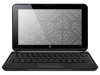
HP Mini 2102, HP Mini 210, and Compaq Mini 210 Maintenance and Service Guide - HP Mini 210-1036TU | HP Mini 2102, HP Mini 210, and Compaq Mini 210 - Maintenanc - Page 2
to change without notice. The only warranties for HP products and services are set forth in the express warranty statements accompanying such products and services. Nothing herein should be construed as constituting an additional warranty. HP shall not be liable for technical or editorial errors - HP Mini 210-1036TU | HP Mini 2102, HP Mini 210, and Compaq Mini 210 - Maintenanc - Page 3
, such as an adjoining optional printer, or a soft surface, such as pillows or rugs or clothing, to block airflow. Also, do not allow the AC adapter to contact the skin or a soft surface, such as pillows or rugs or clothing, during operation. The device and the AC - HP Mini 210-1036TU | HP Mini 2102, HP Mini 210, and Compaq Mini 210 - Maintenanc - Page 4
iv Safety warning notice - HP Mini 210-1036TU | HP Mini 2102, HP Mini 210, and Compaq Mini 210 - Maintenanc - Page 5
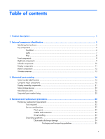
Product description ...1 2 External component identification 5 Identifying the hardware ...5 Top components ...6 TouchPad ...6 Lights ...7 Keys ...8 listing 25 4 Removal and replacement procedures 32 Preliminary replacement requirements 32 Tools required ...32 Service considerations 32 Plastic - HP Mini 210-1036TU | HP Mini 2102, HP Mini 210, and Compaq Mini 210 - Maintenanc - Page 6
SIM ...39 Service cover ...40 Hard drive ...43 WWAN module ...45 WLAN module ...47 Memory module ...49 RTC battery ...51 Keyboard ...52 Top cover ...56 Speakers ...59 Display assembly ...61 System board ...64 Fan/heat sink assembly 67 Power connector cable 69 - HP Mini 210-1036TU | HP Mini 2102, HP Mini 210, and Compaq Mini 210 - Maintenanc - Page 7
to a previous date and time 79 Backing up and recovering using HP Recovery Manager 80 Backing up your information 80 Creating a set of ...88 RJ-45 (network) ...89 Universal Serial Bus ...89 8 Power cord set requirements 90 Requirements for all countries 90 Requirements for specific countries and - HP Mini 210-1036TU | HP Mini 2102, HP Mini 210, and Compaq Mini 210 - Maintenanc - Page 8
viii - HP Mini 210-1036TU | HP Mini 2102, HP Mini 210, and Compaq Mini 210 - Maintenanc - Page 9
description Category Product Name Processor Chipset Graphics Panels Memory Description HP Mini 2102 and HP Mini 210 HP Mini 2102 √ HP Mini 210 √ Compaq Mini 210 Intel® Atom™ N455 1.66-GHz processor, 512-KB level √ 2 cache, 667-MHz front-side bus (FSB) Intel® Atom™ N475 1.83-GHz processor - HP Mini 210-1036TU | HP Mini 2102, HP Mini 210, and Compaq Mini 210 - Maintenanc - Page 10
Diskette drive Audio/Visual Modem Ethernet Description HP Mini 2102 and HP Mini 210 Supports the following configurations: √ ● 1-GB total system memory NOTE: Supported on computers with all operating systems ● 2-GB total system memory NOTE: Supported only on computers with Windows 7 Premium - HP Mini 210-1036TU | HP Mini 2102, HP Mini 210, and Compaq Mini 210 - Maintenanc - Page 11
√ Integrated WWAN by way of HP un2400 Mobile √ Broadband Module (optional supporting up to 1600 x 900 external resolution @ √ 60Hz, hot plug /unplug, and auto detection for correct output to wide-aspect vs. standard aspect video 3-pin AC power √ 93% island-style keyboard √ Compaq Mini 210 - HP Mini 210-1036TU | HP Mini 2102, HP Mini 210, and Compaq Mini 210 - Maintenanc - Page 12
Category Power requirements Security Operating system Serviceability Description HP Mini 2102 and HP Mini 210 HP Clikpad TouchPad with multi-touch/gesture support √ No numeric pad supported. TouchPad with 2 TouchPad buttons and 2-way scrolling (taps enabled and some gestures enabled by default - HP Mini 210-1036TU | HP Mini 2102, HP Mini 210, and Compaq Mini 210 - Maintenanc - Page 13
2 External component identification Identifying the hardware Components included with the computer may vary by region and model. The illustrations in this chapter identify the standard features on most computer models. To see a list of hardware installed in the computer, follow these steps: 1. - HP Mini 210-1036TU | HP Mini 2102, HP Mini 210, and Compaq Mini 210 - Maintenanc - Page 14
Top components TouchPad Item Component Description (1) TouchPad on/off button Turns the TouchPad on and off. Quickly double-tap the button to turn the TouchPad on and off. (2) TouchPad Moves the pointer and selects or activates items on the screen. (3) Left TouchPad button* Functions like - HP Mini 210-1036TU | HP Mini 2102, HP Mini 210, and Compaq Mini 210 - Maintenanc - Page 15
Lights Item Component (1) TouchPad light (2) Caps lock light (3) Mute light (4) Wireless light Description ● On: The TouchPad is disabled. ● Off: The TouchPad is enabled. On: Caps lock is on. On: Speaker sound is off. ● White: An integrated wireless device, such as a wireless local area network ( - HP Mini 210-1036TU | HP Mini 2102, HP Mini 210, and Compaq Mini 210 - Maintenanc - Page 16
(2) Description Execute frequently used system functions. Executes frequently used system functions when pressed in combination with a function key or the esc key. Displays the Windows Start menu. Displays a shortcut menu for items beneath the pointer. Description Produce sound. 8 Chapter - HP Mini 210-1036TU | HP Mini 2102, HP Mini 210, and Compaq Mini 210 - Maintenanc - Page 17
Right-side components item Component (1) Digital Media Slot (2) Power light (3) Power switch (4) Vent (5) USB ports (2) Description Supports the following optional digital card formats: ● Memory Stick (MS) ● MS/Pro ● MultiMediaCard (MMC) ● Secure Digital High Capacity (SDHC) Memory Card (standard - HP Mini 210-1036TU | HP Mini 2102, HP Mini 210, and Compaq Mini 210 - Maintenanc - Page 18
Vent (5) Drive light Description Connects an AC adapter. ● Off: The computer is running on battery power. ● Blinking white: The battery has reached being accessed. ● Amber (select models only): HP ProtectSmart Hard Drive Protection has temporarily parked the hard drive. 10 - HP Mini 210-1036TU | HP Mini 2102, HP Mini 210, and Compaq Mini 210 - Maintenanc - Page 19
an optional USB device. Produces sound when connected to optional powered stereo speakers, headphones, earbuds, a headset, or television audio Internal microphone Description Initiates Standby if the display is closed while the power is on. NOTE: The display switch is not visible from the outside - HP Mini 210-1036TU | HP Mini 2102, HP Mini 210, and Compaq Mini 210 - Maintenanc - Page 20
Bottom components item Component (1) Battery release latches (2) (2) Battery bay Description Release the battery from the battery bay. Holds the battery. 12 Chapter 2 External component identification - HP Mini 210-1036TU | HP Mini 2102, HP Mini 210, and Compaq Mini 210 - Maintenanc - Page 21
to the section of the Regulatory, Safety and Environmental Notices that applies to your country or region. To access these notices, select Start > Help and Support > User Guides. Wireless antennas 13 - HP Mini 210-1036TU | HP Mini 2102, HP Mini 210, and Compaq Mini 210 - Maintenanc - Page 22
area of the computer, provides important information that you may need when contacting technical support. NOTE: Serial number label location, format, and color vary on select models. (1) Product name (2) Serial number (3) Product number (4) Warranty period (5) Model description (select models) 14 - HP Mini 210-1036TU | HP Mini 2102, HP Mini 210, and Compaq Mini 210 - Maintenanc - Page 23
panel cable, 2 WLAN transceivers and cables, 2 WWAN transceivers and cables, and webcam/microphone module and cable): For use only with HP 2102 and Mini 210 computer models: ● WSVGA, flush glass display assembly in black ● WSVGA, flush glass display assembly in blue 612200-001 612198-001 Computer - HP Mini 210-1036TU | HP Mini 2102, HP Mini 210, and Compaq Mini 210 - Maintenanc - Page 24
glass display assembly in pink ● WSVGA, AntiGlare, standard display assembly in white For use only with Compaq Mini 210 computer models: ● WSVGA, AntiGlare, standard display assembly in black (2) Keyboard (includes cable) Black: ● For use in Belgium ● For use in Brazil ● For use in the Czech - HP Mini 210-1036TU | HP Mini 2102, HP Mini 210, and Compaq Mini 210 - Maintenanc - Page 25
Item Description ● For use in Spain ● For use in Switzerland ● For use in Taiwan ● For use in Thailand ● For use in Turkey ● For use in the United Kingdom ● For use in the United States White (for full-feature models only): ● For use in Belgium ● For use in Brazil ● For use in the Czech Republic ● - HP Mini 210-1036TU | HP Mini 2102, HP Mini 210, and Compaq Mini 210 - Maintenanc - Page 26
Item Description ● For use in the United Kingdom ● For use in the United States Pink (for full-feature models only): ● For use in Belgium ● For use in Brazil ● For use in the Czech Republic ● For use in Denmark, Finland, and Norway ● For use in France ● For use in French Canada ● For use in - HP Mini 210-1036TU | HP Mini 2102, HP Mini 210, and Compaq Mini 210 - Maintenanc - Page 27
Broadcom FLEA, WWAN 608958-001 (6) Fan/heat sink assembly (includes replacement thermal material) 589681-001 (7) Power connector cable 589682-001 (8) Base enclosure (includes 4 rubber feet and power connector bracket) For FF models 596145-001 For DF models 589678-001 In pink 608306-001 - HP Mini 210-1036TU | HP Mini 2102, HP Mini 210, and Compaq Mini 210 - Maintenanc - Page 28
Bluetooth PCI-e Half MiniCard (12) HP un2400 Mobile Broadband WWAN module (13) Hard drive (includes cable adapter, 4 rubber isolators, and hard latches and 2 rubber feet) (15) 3-cell, 28-WHr (includes 2 release latches) ● Service cover ● In blue ● In red ● In silver ● In silver (Brazil only) ● In - HP Mini 210-1036TU | HP Mini 2102, HP Mini 210, and Compaq Mini 210 - Maintenanc - Page 29
(includes WLAN antenna transceivers and cables and WWAN antenna transceivers and cables): For use only with HP Mini 2102 and 210 computer models 589656-001 For use only with Compaq Mini 210 computer models 589655-001 Display panel: 25.7-cm (10.1-in), WSVGA, AntiGlare display panel (For use - HP Mini 210-1036TU | HP Mini 2102, HP Mini 210, and Compaq Mini 210 - Maintenanc - Page 30
and WWAN antenna transceivers and cables): For use only with HP computer models in black 589661-001 For use only with HP computer models in blue 589660-001 For use only with HP computer models in red 589659-001 For use only with HP computer models in silver 589658-001 For use only with - HP Mini 210-1036TU | HP Mini 2102, HP Mini 210, and Compaq Mini 210 - Maintenanc - Page 31
Mass storage devices NOTE: Each hard drive spare part kit includes a cable adapter, bracket, and 4 isolators. Item (1) (3) Description Hard drive: 320-GB, 7200-RPM 250-GB, 7200-RPM, with WWAN 160-GB, 7200-RPM, with WWAN Hard Drive - HP Mini 210-1036TU | HP Mini 2102, HP Mini 210, and Compaq Mini 210 - Maintenanc - Page 32
Miscellaneous parts Description 40-W UMA AC adapter, non-smart RC/V 40-W UMA AC adapter, non-smart RC/V 2W Power cord: For use in Argentina For use in Austalia For use in Brazil For use in Denmark For use in Europe For use in Israel For - HP Mini 210-1036TU | HP Mini 2102, HP Mini 210, and Compaq Mini 210 - Maintenanc - Page 33
Power cord for use in South Africa 490371-BB1 Power cord for use in Israel 490371-D01 Power cord for use in Argentia 490371-D61 Power cord for use in India 531993-001 HP un2400 Mobile Broadband WWAN module 575920-001 Broadcom 4312G 802.11b/g WiFi and 2070 Bluetooth 2.1+EDR Combo Adapter - HP Mini 210-1036TU | HP Mini 2102, HP Mini 210, and Compaq Mini 210 - Maintenanc - Page 34
-001 Display enclosure for use only with HP Mini 2102 and 210 computer models in black (includes WLAN antenna transceivers and cables and WWAN antenna transceivers and cables) 589662-001 Display enclosure for use only with Compaq Mini 210 computer models (includes WLAN antenna transceivers and - HP Mini 210-1036TU | HP Mini 2102, HP Mini 210, and Compaq Mini 210 - Maintenanc - Page 35
bracket) 600707-001 Service cover, for use only with DF computer models 602992-001 Ralink RT3090 802.11b/g/n + BC4 Bluetooth PCI-e half MiniCard 605039-001 25.7-cm (10.1-in) WSVGA, AntiGlare, standard display assembly for use only with HP Mini 2102 and 210 computer models (includes display - HP Mini 210-1036TU | HP Mini 2102, HP Mini 210, and Compaq Mini 210 - Maintenanc - Page 36
9285G 802.11b/g/n Half MiniCard 606695-001 Screw Kit 607978-001 Keyboard, pink, for use only in the United States (includes cable) 607978-031 Keyboard, pink, for use only in the United Kingdom (includes cable) 607978-041 Keyboard, pink, for use only in Germany (includes cable) 607978-051 - HP Mini 210-1036TU | HP Mini 2102, HP Mini 210, and Compaq Mini 210 - Maintenanc - Page 37
(includes cable) 607977-DJ1 Keyboard, white, for use only in Greece (includes cable) 608299-001 Display enclosure for use only with HP Mini 2102 and 210 computer models in white (includes Base enclosure, pink (includes 4 rubber feet and power connector bracket) Sequential part number listing 29 - HP Mini 210-1036TU | HP Mini 2102, HP Mini 210, and Compaq Mini 210 - Maintenanc - Page 38
display panel cable, 2 WLAN transceivers and cables, 2 WWAN transceivers and cables, and webcam/microphone module and cable) 613162-001 40-W UMA AC adapter, non-smart RC/V 2W 614991-001 Service cover, for use only with DF computer models (Brazil only) 30 Chapter 3 Illustrated parts catalog - HP Mini 210-1036TU | HP Mini 2102, HP Mini 210, and Compaq Mini 210 - Maintenanc - Page 39
Spare part number Description 614994-001 Service cover, silver (Brazil only) 615862-001 1-GB memory module (667-MHz, DDR3): 615863-001 2-GB memory module (667-MHz, DDR3): 615864-001 1-GB memory module ( - HP Mini 210-1036TU | HP Mini 2102, HP Mini 210, and Compaq Mini 210 - Maintenanc - Page 40
will need the following tools to complete the removal and replacement procedures: ● Flat-bladed screwdriver ● Magnetic screwdriver ● Phillips P0 and P1 screwdrivers Service . Apply pressure only at the points designated in the maintenance instructions. 32 Chapter 4 Removal and replacement procedures - HP Mini 210-1036TU | HP Mini 2102, HP Mini 210, and Compaq Mini 210 - Maintenanc - Page 41
of shock-proof foam. Avoid dropping drives from any height onto any surface. After removing a hard drive, an optical drive, or a diskette drive, place it in a static-proof bag. Avoid exposing a hard drive to products that have magnetic fields, such as monitors or speakers. Avoid exposing a drive to - HP Mini 210-1036TU | HP Mini 2102, HP Mini 210, and Compaq Mini 210 - Maintenanc - Page 42
but in many cases, ESD contains enough power to alter device parameters or melt silicon To prevent damage to the device when you are removing or installing internal components, observe these precautions: levels generated by different activities. CAUTION: A product can be degraded by as little as 700 - HP Mini 210-1036TU | HP Mini 2102, HP Mini 210, and Compaq Mini 210 - Maintenanc - Page 43
● To avoid hand contact, transport products in static-safe tubes, bags, or grounded tools and equipment. ● Use conductive field service tools, such as cutters, screwdrivers, and vacuums. ● Turn off power and input signals before inserting or removing connectors or test equipment. Preliminary - HP Mini 210-1036TU | HP Mini 2102, HP Mini 210, and Compaq Mini 210 - Maintenanc - Page 44
Conductive tabletop workstations with ground cords of one megohm resistance ● Static-dissipative tables or floor mats with hard ties to the ground ● Field service kits ● Static awareness Floor mats Voltage protection level 1,500 V 7,500 V 5,000 V 36 Chapter 4 Removal and replacement procedures - HP Mini 210-1036TU | HP Mini 2102, HP Mini 210, and Compaq Mini 210 - Maintenanc - Page 45
procedures. There are as many as 33 screws, in 5 different sizes, that must be removed, replaced, or loosened when servicing the computer. Make special note of each screw size and location during removal and replacement. Computer feet The computer feet are adhesive-backed rubber pads. The feet are - HP Mini 210-1036TU | HP Mini 2102, HP Mini 210, and Compaq Mini 210 - Maintenanc - Page 46
system. 2. Disconnect all external devices connected to the computer. 3. Disconnect the power from the computer by first unplugging the power cord from the AC outlet and then unplugging the AC adapter from the computer. Remove the battery: 1. Turn the computer upside-down on a flat surface, with - HP Mini 210-1036TU | HP Mini 2102, HP Mini 210, and Compaq Mini 210 - Maintenanc - Page 47
all external devices connected to the computer. 3. Disconnect the power from the computer by first unplugging the power cord from the AC outlet and then unplugging the AC adapter from the computer. 4. Remove the battery (see Battery on page 38). Remove the SIM: 1. Press in on the SIM (1) to release - HP Mini 210-1036TU | HP Mini 2102, HP Mini 210, and Compaq Mini 210 - Maintenanc - Page 48
devices connected to the computer. 3. Disconnect the power from the computer by first unplugging the power cord from the AC outlet and then unplugging the AC adapter from the computer. 4. Remove the battery (see Battery on page 38). Remove the service cover: 1. Press the right release button - HP Mini 210-1036TU | HP Mini 2102, HP Mini 210, and Compaq Mini 210 - Maintenanc - Page 49
cover (2) by lifting it slightly away from the base enclosure. NOTE: It is normal for the service cover to flex slightly when it is released. You may also hear some popping noises as the service cover tabs disengage from the base enclosure slots. 3. Press the left release button (1). 4. Release the - HP Mini 210-1036TU | HP Mini 2102, HP Mini 210, and Compaq Mini 210 - Maintenanc - Page 50
and forward until it rests at an angle, and then remove the service cover (2). Install the service cover: 1. Place the service cover above the computer at an angle, with the front edge toward the front of the computer. 2. Insert the front edge of the service cover (1) into the front edge of the base - HP Mini 210-1036TU | HP Mini 2102, HP Mini 210, and Compaq Mini 210 - Maintenanc - Page 51
from the computer by first unplugging the power cord from the AC outlet and then unplugging the AC adapter from the computer. 4. Remove the battery (see Battery on page 38). 5. Remove the service cover (see Battery on page 38). Remove the hard drive: 1. Disconnect the hard drive cable (1) from the - HP Mini 210-1036TU | HP Mini 2102, HP Mini 210, and Compaq Mini 210 - Maintenanc - Page 52
it up and to the right at an angle. 4. If it is necessary to replace the hard drive bracket, follow these steps: a. Disconnect the cable adapter (1) from the hard drive. b. Remove the four Phillips PM3.0×3.0 screws (2) that secure the hard drive bracket to the drive - HP Mini 210-1036TU | HP Mini 2102, HP Mini 210, and Compaq Mini 210 - Maintenanc - Page 53
remove the module to restore device functionality, and then contact technical support. Before removing power cord from the AC outlet and then unplugging the AC adapter from the computer. 4. Remove the battery (see Battery on page 38). 5. Remove the service cover (see Service cover on page 40). Remove - HP Mini 210-1036TU | HP Mini 2102, HP Mini 210, and Compaq Mini 210 - Maintenanc - Page 54
with a notch (5) to prevent incorrect insertion of the WWAN module into the WWAN module slot. Reverse this procedure to install the WWAN module. 46 Chapter 4 Removal and replacement procedures - HP Mini 210-1036TU | HP Mini 2102, HP Mini 210, and Compaq Mini 210 - Maintenanc - Page 55
the device by first unplugging the power cord from the AC outlet and then unplugging the AC adapter from the computer. 4. Remove the battery (see Battery on page 38). 5. Remove the service cover (see Service cover on page 40). Remove the WLAN module: 1. Disconnect the WLAN antenna cables (1) from - HP Mini 210-1036TU | HP Mini 2102, HP Mini 210, and Compaq Mini 210 - Maintenanc - Page 56
with a notch (4) to prevent incorrect insertion of the WLAN module into the WLAN module slot. Reverse this procedure to install the WLAN module. 48 Chapter 4 Removal and replacement procedures - HP Mini 210-1036TU | HP Mini 2102, HP Mini 210, and Compaq Mini 210 - Maintenanc - Page 57
from the computer by first unplugging the power cord from the AC outlet and then unplugging the AC adapter from the computer. 4. Remove the battery (see Battery on page 38). 5. Remove the service cover (see Service cover on page 40). Remove the memory module: 1. Pull away the retention clips (1) on - HP Mini 210-1036TU | HP Mini 2102, HP Mini 210, and Compaq Mini 210 - Maintenanc - Page 58
: Memory modules are designed with a notch (3) to prevent incorrect insertion into the memory module slot. Reverse this procedure to install the memory module. 50 Chapter 4 Removal and replacement procedures - HP Mini 210-1036TU | HP Mini 2102, HP Mini 210, and Compaq Mini 210 - Maintenanc - Page 59
from the computer by first unplugging the power cord from the AC outlet and then unplugging the AC adapter from the computer. 4. Remove the battery (see Battery on page 38). 5. Remove the service cover (see Service cover on page 40). Remove the RTC battery: ▲ Remove the RTC battery from the socket - HP Mini 210-1036TU | HP Mini 2102, HP Mini 210, and Compaq Mini 210 - Maintenanc - Page 60
spare part kit includes a keyboard cable. For use in: In white: Belgium Brazil The Czech Korea Spain Switzerland Taiwan Thailand Turkey The United Kingdom The United States 52 Chapter 4 Removal and replacement procedures Spare part number 607977-B31 607977-131 607977-251 607977-171 607977 - HP Mini 210-1036TU | HP Mini 2102, HP Mini 210, and Compaq Mini 210 - Maintenanc - Page 61
141 590527-031 590527-001 Before removing the keyboard, follow these steps: 1. power from the computer by first unplugging the power cord from the AC outlet and then unplugging the AC adapter from the computer. 4. Remove the battery (see Battery on page 38). 5. Remove the service cover (see Service - HP Mini 210-1036TU | HP Mini 2102, HP Mini 210, and Compaq Mini 210 - Maintenanc - Page 62
(2) back until the keyboard cable and connector are accessible. 6. Release the zero insertion force (ZIF) connector (3) to which the keyboard cable is attached, and then disconnect the keyboard cable (4) from the system board. 7. Remove the keyboard. 54 Chapter 4 Removal and replacement procedures - HP Mini 210-1036TU | HP Mini 2102, HP Mini 210, and Compaq Mini 210 - Maintenanc - Page 63
Reverse this procedure to install the keyboard. Component replacement procedures 55 - HP Mini 210-1036TU | HP Mini 2102, HP Mini 210, and Compaq Mini 210 - Maintenanc - Page 64
by first unplugging the power cord from the AC outlet and then unplugging the AC adapter from the computer. 4. Remove the battery (see Battery on page 38). 5. Remove the service cover (see Service cover on page 40). 6. Remove the keyboard (see Keyboard on page 52). Remove the top cover. 1. Turn - HP Mini 210-1036TU | HP Mini 2102, HP Mini 210, and Compaq Mini 210 - Maintenanc - Page 65
board. 6. Release the ZIF connector (2) to which the TouchPad cable is connected, and then disconnect the TouchPad cable (3) from the system board. 7. Remove the five Phillips PM2.0×6.0 screws that secure the top cover to the base enclosure. 8. Release the top cover (1) by lifting the rear edge - HP Mini 210-1036TU | HP Mini 2102, HP Mini 210, and Compaq Mini 210 - Maintenanc - Page 66
9. Remove the top cover (2) by lifting it straight up. Reverse this procedure to install the top cover. 58 Chapter 4 Removal and replacement procedures - HP Mini 210-1036TU | HP Mini 2102, HP Mini 210, and Compaq Mini 210 - Maintenanc - Page 67
the computer by first unplugging the power cord from the AC outlet and then unplugging the AC Adapter from the computer. 4. Remove the battery (see Battery on page 38). 5. Remove the following components: a. Service cover (see Service cover on page 40). b. Keyboard (see Keyboard on page 52). c. Top - HP Mini 210-1036TU | HP Mini 2102, HP Mini 210, and Compaq Mini 210 - Maintenanc - Page 68
Reverse this procedure to install the speakers. 60 Chapter 4 Removal and replacement procedures - HP Mini 210-1036TU | HP Mini 2102, HP Mini 210, and Compaq Mini 210 - Maintenanc - Page 69
connected to the computer. 3. Disconnect the power from the computer by first unplugging the power cord from the AC outlet and then unplugging the AC adapter from the computer. 4. Remove the battery (see Battery on page 38). 5. Remove the service cover (see Service cover on page 40). 6. Disconnect - HP Mini 210-1036TU | HP Mini 2102, HP Mini 210, and Compaq Mini 210 - Maintenanc - Page 70
Remove the display assembly: 1. Close the computer. 2. Turn the computer upside down, with the front toward you. 3. Release the WLAN antenna . 5. Open the computer as far as it will open. 6. Disconnect the display panel cable (1) from the system board. 62 Chapter 4 Removal and replacement procedures - HP Mini 210-1036TU | HP Mini 2102, HP Mini 210, and Compaq Mini 210 - Maintenanc - Page 71
(2) from the clip built into the base enclosure. CAUTION: Support the display assembly when removing the following screws. Failure to support the display assembly can result in damage to the display assembly and other device components. 8. Remove the two Phillips PM2.0×4.0 screws (1) that secure the - HP Mini 210-1036TU | HP Mini 2102, HP Mini 210, and Compaq Mini 210 - Maintenanc - Page 72
connected to the computer. 3. Disconnect the power from the computer by first unplugging the power cord from the AC outlet and then unplugging the AC adapter from the computer. 4. Remove the battery (see Battery on page 38). 5. Remove the service cover (see Service cover on page 40). 6. Disconnect - HP Mini 210-1036TU | HP Mini 2102, HP Mini 210, and Compaq Mini 210 - Maintenanc - Page 73
the system board: 1. Disconnect the display panel cable (1) from the system board. 2. Disconnect the power connector cable (2) from the system board. 3. Remove the Phillips PM2.0×4.0 screw (1) that secures the system board to the base enclosure. 4. Lift the right side of the system board (2) until - HP Mini 210-1036TU | HP Mini 2102, HP Mini 210, and Compaq Mini 210 - Maintenanc - Page 74
5. Remove the system board (3) by sliding it up and away from the base enclosure. Reverse the procedure to install the system board. 66 Chapter 4 Removal and replacement procedures - HP Mini 210-1036TU | HP Mini 2102, HP Mini 210, and Compaq Mini 210 - Maintenanc - Page 75
power from the computer by first unplugging the power cord from the AC outlet and then unplugging the AC adapter from the computer. 4. Remove the battery (see Battery on page 38). 5. Remove the service cover (see Service 47). 9. Remove the following components: a. Keyboard (see Keyboard on page 52 - HP Mini 210-1036TU | HP Mini 2102, HP Mini 210, and Compaq Mini 210 - Maintenanc - Page 76
from the surfaces of the fan/heat sink assembly and the system board each time the fan/heat sink assembly is removed: Thermal paste is used on the processor (1) and the fan/heat sink assembly section (2) that services it. Reverse this procedure to install the fan/heat sink assembly. 68 Chapter - HP Mini 210-1036TU | HP Mini 2102, HP Mini 210, and Compaq Mini 210 - Maintenanc - Page 77
power from the computer by first unplugging the power cord from the AC outlet and then unplugging the AC adapter from the computer. 4. Remove the battery (see Battery on page 38). 5. Remove the service cover (see Service 47). 9. Remove the following components: a. Keyboard (see Keyboard on page 52 - HP Mini 210-1036TU | HP Mini 2102, HP Mini 210, and Compaq Mini 210 - Maintenanc - Page 78
3. Remove the power connector cable (3). Reverse this procedure to install the power connector cable. 70 Chapter 4 Removal and replacement procedures - HP Mini 210-1036TU | HP Mini 2102, HP Mini 210, and Compaq Mini 210 - Maintenanc - Page 79
When a confirmation prompt with your language selected is displayed, press enter. 5. To save your change and exit Setup Utility, use the arrow keys to select Exit > Exit Saving Changes, and then press enter. Your change goes into effect immediately. Your change goes into effect immediately. Starting - HP Mini 210-1036TU | HP Mini 2102, HP Mini 210, and Compaq Mini 210 - Maintenanc - Page 80
Navigating and selecting in Setup Utility Because Setup Utility is not Windows based, it does not support the TouchPad. Navigation and selection are by keystroke. ● To choose a menu or a menu item, use the arrow keys. ● To choose an item in a list or to toggle a field, for example an Enable/Disable - HP Mini 210-1036TU | HP Mini 2102, HP Mini 210, and Compaq Mini 210 - Maintenanc - Page 81
to return to the menu display. Then use the arrow keys to select Exit > Exit Saving Changes, and then press items listed in this chapter may not be supported by your computer. Select System information To do BIOS. Security Menu Select Administrator password Power-On password To do this Enter, - HP Mini 210-1036TU | HP Mini 2102, HP Mini 210, and Compaq Mini 210 - Maintenanc - Page 82
System Configuration Menu Select Language Support Processor C4 State Boot Options Diagnostics Menu 5, 10, 15, 20). ● HP QuickWeb―Enable/disable the QuickWeb Boot menu in Setup Utility. ● Internal Network Adapter boot―Enable/disable boot from Internal Network Adapter. ● Boot Device Priority―Set the - HP Mini 210-1036TU | HP Mini 2102, HP Mini 210, and Compaq Mini 210 - Maintenanc - Page 83
, you may have one of the following backup and recovery solutions: ● Roxio BackOnTrack ● HP Recovery Manager NOTE: For detailed information, perform a search for these topics in Help and Support. Backing up and recovering using Roxio BackOnTrack Successful recovery after a system failure depends on - HP Mini 210-1036TU | HP Mini 2102, HP Mini 210, and Compaq Mini 210 - Maintenanc - Page 84
sure that the computer is connected to AC power before you start the backup process. 1. screen. 8. Follow the on-screen instructions. Performing a recovery In case of state if a software-related problem occurs. The Instant Restore saving the current computer state manually. For more information about - HP Mini 210-1036TU | HP Mini 2102, HP Mini 210, and Compaq Mini 210 - Maintenanc - Page 85
Disaster Recovery, you need a USB flash drive hp.com/support, and select your country or region. 3. Enter the SoftPaq number SP42226 in the Search box, press enter, and then follow the on-screen instructions , and then pressing f9. 4. Use the arrow keys to select the USB flash drive, and then press - HP Mini 210-1036TU | HP Mini 2102, HP Mini 210, and Compaq Mini 210 - Maintenanc - Page 86
: NOTE: Be sure that the computer is connected to AC power before you start the backup process. NOTE: The backup process and then click Backup and Restore. 2. Follow the on-screen instructions to set up and create a backup. NOTE: Windows includes Support for more information. 78 Chapter 6 Backup and - HP Mini 210-1036TU | HP Mini 2102, HP Mini 210, and Compaq Mini 210 - Maintenanc - Page 87
tab. 4. Under Protection Settings, select the disk for which you want to create a restore point. 5. Click Create. 6. Follow the on-screen instructions. Restoring to a previous date and time To revert to a restore point (created at a previous date and time) when the computer was functioning - HP Mini 210-1036TU | HP Mini 2102, HP Mini 210, and Compaq Mini 210 - Maintenanc - Page 88
tools provided by the operating system and by HP Recovery Manager software are designed to help you Creating a set of recovery discs ● Creating system restore points ● Recovering a program or driver ● Performing a full system recovery Backing up your information As you add new software and data - HP Mini 210-1036TU | HP Mini 2102, HP Mini 210, and Compaq Mini 210 - Maintenanc - Page 89
. Creating a set of recovery discs HP recommends that you create recovery discs to before creating recovery discs: ● You will need high-quality DVD-R, DVD+R, BD-R (writable . ● The computer must be connected to AC power during this process. ● Only one set of recovery instructions. Windows 7 81 - HP Mini 210-1036TU | HP Mini 2102, HP Mini 210, and Compaq Mini 210 - Maintenanc - Page 90
Start, and then click Help and Support. NOTE: Recovery Manager recovers only a hub or docking station. 3. Follow the on-screen instructions. Recovering using the partition on the hard drive (select NOTE: This method of recovery is also an HP Recovery Manager solution. NOTE: Computers with an SSD - HP Mini 210-1036TU | HP Mini 2102, HP Mini 210, and Compaq Mini 210 - Maintenanc - Page 91
, click System Recovery. 3. Follow the on-screen instructions. Windows XP To protect your information, back up access the Disaster Recovery utility. Therefore, HP recommends that you download the Disaster Recovery utility for these topics in Help and Support. Backing up your information Successful - HP Mini 210-1036TU | HP Mini 2102, HP Mini 210, and Compaq Mini 210 - Maintenanc - Page 92
sure that the computer is connected to AC power before you start the backup process. 1. screen. 8. Follow the on-screen instructions. Performing a recovery In case of state if a software-related problem occurs. The Instant Restore saving the current computer state manually. For more information about - HP Mini 210-1036TU | HP Mini 2102, HP Mini 210, and Compaq Mini 210 - Maintenanc - Page 93
Disaster Recovery, you need a USB flash drive hp.com/support, and select your country or region. 3. Enter the SoftPaq number SP42226 in the Search box, press enter, and then follow the on-screen instructions , and then pressing f9. 4. Use the arrow keys to select the USB flash drive, and then press - HP Mini 210-1036TU | HP Mini 2102, HP Mini 210, and Compaq Mini 210 - Maintenanc - Page 94
steps: 1. Restart the computer. NOTE: If the operating system has stopped responding and the computer screen is blue, restart the computer by turning the power switch off and then on. 2. When the computer logo is displayed on the screen, press f6 repeatedly until the Windows status bar is displayed - HP Mini 210-1036TU | HP Mini 2102, HP Mini 210, and Compaq Mini 210 - Maintenanc - Page 95
7 Connector pin assignments Audio-in (microphone) Pin 1 2 3 Audio-out (headphone) Signal Audio signal in Audio signal in Ground Pin Signal 1 Audio out, left channel 2 Audio out, right channel 3 Ground Audio-in (microphone) 87 - HP Mini 210-1036TU | HP Mini 2102, HP Mini 210, and Compaq Mini 210 - Maintenanc - Page 96
External monitor Pin 1 2 3 4 5 6 7 8 9 10 11 12 13 14 15 Signal Red analog Green analog Blue analog Not connected Ground Ground analog Ground analog Ground analog +5 VDC Ground Monitor detect DDC 2B data Horizontal sync Vertical sync DDC 2B clock 88 Chapter 7 Connector pin assignments - HP Mini 210-1036TU | HP Mini 2102, HP Mini 210, and Compaq Mini 210 - Maintenanc - Page 97
RJ-45 (network) Pin 1 2 3 4 5 6 7 8 Universal Serial Bus Signal Transmit + Transmit Receive + Unused Unused Receive Unused Unused Pin Signal 1 +5 VDC 2 Data 3 Data + 4 Ground RJ-45 (network) 89 - HP Mini 210-1036TU | HP Mini 2102, HP Mini 210, and Compaq Mini 210 - Maintenanc - Page 98
set included with the computer meets the requirements for use in the country or region where the equipment is purchased. Power cord sets for use in other countries and regions must meet the requirements of the country or region where the computer is used. Requirements for all - HP Mini 210-1036TU | HP Mini 2102, HP Mini 210, and Compaq Mini 210 - Maintenanc - Page 99
of the agency responsible for evaluation in the country or region where it will be used. 5. The flexible cord must be Type VCTF, 3-conductor, 0.75-mm² conductor size. Power cord set fittings (appliance coupler and wall plug) must bear the certification mark of the agency responsible for evaluation - HP Mini 210-1036TU | HP Mini 2102, HP Mini 210, and Compaq Mini 210 - Maintenanc - Page 100
the backlight. When you remove these components, handle them carefully. NOTE: Materials Disposal. This HP product contains mercury in the backlight Web site at http://www.eiai.org. This section provides disassembly instructions for the display assembly. The display assembly must be disassembled to - HP Mini 210-1036TU | HP Mini 2102, HP Mini 210, and Compaq Mini 210 - Maintenanc - Page 101
Perform the following steps: 1. Remove all screw covers (1) and screws (2) that secure the display bezel to the display assembly. 2. Lift up and out the top and bottom inside edges (2) of the display bezel until the bezel disengages from the display assembly. 3. Remove the display bezel 3. Display 93 - HP Mini 210-1036TU | HP Mini 2102, HP Mini 210, and Compaq Mini 210 - Maintenanc - Page 102
the display panel assembly (2) from the display enclosure. 7. Turn the display panel assembly upside down. 8. Remove all screws that secure the display panel frame to the display panel. 9. Use a sharp-edged tool to cut the tape (1) that secures the sides of - HP Mini 210-1036TU | HP Mini 2102, HP Mini 210, and Compaq Mini 210 - Maintenanc - Page 103
cover to the display panel. 12. Lift the top edge of the backlight cover (2) and swing it outward. 13. Remove the backlight cover. 14. Turn the display panel right-side up. 15. Remove the backlight cables (1) from the clip (2) in the display panel. 16. Turn the display panel upside down. Display - HP Mini 210-1036TU | HP Mini 2102, HP Mini 210, and Compaq Mini 210 - Maintenanc - Page 104
and handling the backlight to avoid damaging this component and causing exposure to the mercury. 18. Remove the backlight from the backlight frame. 19. Disconnect the display cable (1) from the LCD panel. 20. Remove the screws (2) that secure the LCD panel to the display rear panel. 21. Release the - HP Mini 210-1036TU | HP Mini 2102, HP Mini 210, and Compaq Mini 210 - Maintenanc - Page 105
22. Release the tape (4) that secures the LCD panel to the display rear panel. 23. Remove the LCD panel. 24. Recycle the LCD panel and backlight. Display 97 - HP Mini 210-1036TU | HP Mini 2102, HP Mini 210, and Compaq Mini 210 - Maintenanc - Page 106
numbers 30 AC adapter, spare part numbers 24, 25 action keys 8 antenna locations 13 audio, product description 2 service considerations 33 D devices, mass storage 23 Diagnostics Menu, Setup Utility 74 Digital Media Slot 9 diskette drive precautions 33 product description 2 display assembly removal - HP Mini 210-1036TU | HP Mini 2102, HP Mini 210, and Compaq Mini 210 - Maintenanc - Page 107
11 network 10 RJ-45 10 K keyboard product description 3 removal 52 spare part numbers 16, 26, 27, 28, 29 , 29, 52 keys action 8 fn 8 Windows applications 8 Windows logo 8 L language support 74 lights battery 10 caps lock 7 drive 10 mute 7 power 9 TouchPad 7 webcam 11 wireless 7 M Main Menu - HP Mini 210-1036TU | HP Mini 2102, HP Mini 210, and Compaq Mini 210 - Maintenanc - Page 108
media cards 3 keyboard 3 memory module 1 modem 2 operating system 4 optical drive 2 panels 1 pointing device 3 ports 3 power requirements 4 processors 1 product name 1 security 4 serviceability 4 video 2 wireless 3 product name 1 R recycling battery 92 display 92 removal/replacement preliminaries - HP Mini 210-1036TU | HP Mini 2102, HP Mini 210, and Compaq Mini 210 - Maintenanc - Page 109
, spare part numbers 22, 25 Windows applications key 8 Windows logo key 8 wireless antenna locations 13 wireless light 7 wireless module, product description 3 WLAN module removal 47 spare part numbers 19, 25, 27, 28, 47 workstation guidelines 35 WWAN module removal 45 spare part numbers 20, 25, 45
-
 1
1 -
 2
2 -
 3
3 -
 4
4 -
 5
5 -
 6
6 -
 7
7 -
8
-
9
-
10
-
11
-
12
-
13
-
14
-
15
-
16
-
17
-
18
-
19
-
20
-
21
-
22
-
23
-
24
-
25
-
26
-
27
-
28
-
29
-
30
-
31
-
32
-
33
-
34
-
35
-
36
-
37
-
38
-
39
-
40
-
41
-
42
-
43
-
44
-
45
-
46
-
47
-
48
-
49
-
50
-
51
-
52
-
53
-
54
-
55
-
56
-
57
-
58
-
59
-
60
-
61
-
62
-
63
-
64
-
65
-
66
-
67
-
68
-
69
-
70
-
71
-
72
-
73
-
74
-
75
-
76
-
77
-
78
-
79
-
80
-
81
-
82
-
83
-
84
-
85
-
86
-
87
-
88
-
89
-
90
-
91
-
92
-
93
-
94
-
95
-
96
-
97
-
98
-
99
-
100
-
101
-
102
-
103
-
104
-
105
-
106
-
107
-
108
-
109
 |
 |

HP Mini 2102, HP Mini 210, and
Compaq Mini 210
Maintenance and Service Guide