HP Point of Sale rp5000 Hardware Reference Guide (2nd Edition)
HP Point of Sale rp5000 Manual
 |
View all HP Point of Sale rp5000 manuals
Add to My Manuals
Save this manual to your list of manuals |
HP Point of Sale rp5000 manual content summary:
- HP Point of Sale rp5000 | Hardware Reference Guide (2nd Edition) - Page 1
Hardware Reference Guide HP Point of Sale System rp5000 Document Part Number: 337853-002 June 2005 This guide provides basic information for upgrading this computer model. - HP Point of Sale rp5000 | Hardware Reference Guide (2nd Edition) - Page 2
notice. Windows is a trademark of Microsoft Corporation in the U.S. and other countries. The only warranties for HP products and services are equipment or loss of information. Hardware Reference Guide HP Point of Sale System rp5000 First Edition August 2003 Second Edition June 2005 Document Part Number: - HP Point of Sale rp5000 | Hardware Reference Guide (2nd Edition) - Page 3
Panel Components 1-3 Windows Logo Key 1-4 Removing the Serial Port Cap 1-5 Serial Number and Product Number Location 1-6 2 Hardware Upgrades Serviceability Features 2-1 Warnings and Cautions 2-1 Removing the Computer Access Panel and Front Bezel 2-2 Installing Additional Memory 2-4 DIMMs - HP Point of Sale rp5000 | Hardware Reference Guide (2nd Edition) - Page 4
Preventing Electrostatic Damage F-1 Grounding Methods F-1 G Routine Computer Care and Shipping Preparation Routine Computer Care G-1 Optical Drive Precautions G-2 Operation G-2 Cleaning G-2 Safety G-2 Shipping Preparation G-3 Index iv www.hp.com Hardware Reference Guide - HP Point of Sale rp5000 | Hardware Reference Guide (2nd Edition) - Page 5
the model. For a complete listing of the hardware and software installed in the computer, run the Diagnostics for Windows® utility. Instructions for using this utility are provided in the Troubleshooting Guide on the Documentation CD. HP Point of Sale System rp5000 Hardware Reference Guide www.hp - HP Point of Sale rp5000 | Hardware Reference Guide (2nd Edition) - Page 6
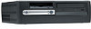
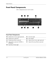
Product Features Front Panel Components Drive configuration may vary by model. Front Panel Components 1 Diskette Drive Activity Light (optional) 2 Diskette Drive (optional) 3 8 Optical Drive Activity Light (optional) 9 Optical Drive Eject Button (optional) 1-2 www.hp.com Hardware Reference Guide - HP Point of Sale rp5000 | Hardware Reference Guide (2nd Edition) - Page 7
7 n RJ-45 Network Connector 8 l Parallel Connector 9 c Monitor Connector 4 a PS/2 Keyboard Connector 5 o Universal Serial Bus (USB) : o USB+Power Connector ; k Audio connector 6 m Serial Connector ✎ Arrangement and number of connectors may vary by model. Hardware Reference Guide www.hp.com 1-3 - HP Point of Sale rp5000 | Hardware Reference Guide (2nd Edition) - Page 8
in the Windows operating system. Windows Logo Key Functions Windows Logo Key Windows Logo Key + d Windows Logo Key + m Shift + Windows Logo Key + m Windows Logo Key + e Windows Logo Key + f Windows Logo Key + Ctrl + f Windows Logo Key + F1 Windows Logo Key + l Windows Logo Key + r Windows Logo Key - HP Point of Sale rp5000 | Hardware Reference Guide (2nd Edition) - Page 9
Product Features Removing the Serial Port Cap The powered serial ports have been protected with a plastic cap. Turn off the computer and remove the cap before connecting a powered serial Point of Sale device. Removing the Serial Port Cap Hardware Reference Guide www.hp.com 1-5 - HP Point of Sale rp5000 | Hardware Reference Guide (2nd Edition) - Page 10
a unique serial number and product number that are located on the top cover of the computer. Keep these numbers available for use when contacting customer service for assistance. Serial Number and Product Number Location 1-6 www.hp.com Hardware Reference Guide - HP Point of Sale rp5000 | Hardware Reference Guide (2nd Edition) - Page 11
it easy to upgrade and service. No tools are needed for most of the installation procedures described in this chapter. Warnings and Cautions Before performing upgrades be sure to carefully read all of the applicable instructions, cautions, and warnings in this guide. Å WARNING: To reduce the risk - HP Point of Sale rp5000 | Hardware Reference Guide (2nd Edition) - Page 12
Computer Access Panel and Front Bezel 1. Turn off the computer properly through the operating system, then turn off any external devices. 2. Disconnect the power cord from the power outlet panel up and off the chassis. Removing the Computer Access Panel 2-2 www.hp.com Hardware Reference Guide - HP Point of Sale rp5000 | Hardware Reference Guide (2nd Edition) - Page 13
two bezel bottom tabs, then rotate the front bezel forward to snap the three tabs on the top of the bezel in place. Hardware Reference Guide www.hp.com 2-3 - HP Point of Sale rp5000 | Hardware Reference Guide (2nd Edition) - Page 14
(CL = 2 or CL = 2.5) ■ contain the mandatory JEDEC SPD information In addition, the computer supports: ■ 64 Mbit, 128 Mbit, 256 Mbit, and 512 Mbit non-ECC memory technology ■ single-sided or double-sided DIMMS (does not support double-sided X16 DDR1 DIMMS) 2-4 www.hp.com Hardware Reference Guide - HP Point of Sale rp5000 | Hardware Reference Guide (2nd Edition) - Page 15
processor bus frequencies are required for the system to run at the supported memory frequencies. DIMM If Processor Bus Frequency is Memory Frequency is PC2100 400 MHz 266 MHz PC2100 Appendix F, "Electrostatic Discharge" for more information. Hardware Reference Guide www.hp.com 2-5 - HP Point of Sale rp5000 | Hardware Reference Guide (2nd Edition) - Page 16
Rotate the Easy Access drive bay to an upright position. Rotating the Easy Access Drive Bay 5. Locate the memory module sockets. Å WARNING: To reduce risk of personal injury from hot surfaces, allow the internal system components to cool before touching. 2-6 www.hp.com Hardware Reference Guide - HP Point of Sale rp5000 | Hardware Reference Guide (2nd Edition) - Page 17
can be installed in only one way. Match the notch on the module with the tab on the memory socket. 7. Push the module down into the socket, ensuring that the module is fully inserted and properly seated. Make sure the latches are in the closed position 3. Hardware Reference Guide www.hp.com 2-7 - HP Point of Sale rp5000 | Hardware Reference Guide (2nd Edition) - Page 18
bezel and computer access panel. The computer automatically recognizes the additional memory the next time you power on the computer. Removing the Expansion card cage: 1. Turn off the computer properly through the operating system, then turn off any external devices. 2. Disconnect the power cord - HP Point of Sale rp5000 | Hardware Reference Guide (2nd Edition) - Page 19
Card Cage To replace the expansion card cage, reverse the above procedure. ✎ Ensure that the riser card seats properly into the PCI connector on the system board when reinstalling the expansion card cage. Hardware Reference Guide www.hp.com 2-9 - HP Point of Sale rp5000 | Hardware Reference Guide (2nd Edition) - Page 20
) in length. To install an expansion card: 1. Turn off the computer properly through the operating system, then turn off any external devices. 2. Disconnect the power cord from the power outlet and disconnect it out 2. 2-10 Removing the Expansion Slot Cover www.hp.com Hardware Reference Guide - HP Point of Sale rp5000 | Hardware Reference Guide (2nd Edition) - Page 21
a new card or cover the open slot (for example, with a metal slot cover) for proper air circulation to cool internal components during operation. Hardware Reference Guide www.hp.com 2-11 - HP Point of Sale rp5000 | Hardware Reference Guide (2nd Edition) - Page 22
HP USB+Power card must be installed in the Acclerated Graphics Port (AGP) slot. ✎ An AGP card will not work in the AGP slot. To remove the card from the AGP slot: 1. Turn off the computer properly through the operating system Locate the USB+Power card on the system board. 5. Lift up the slot cover - HP Point of Sale rp5000 | Hardware Reference Guide (2nd Edition) - Page 23
not to scrape the card against other components. Removing the USB+Power Card To replace the USB+Power card, reverse the above procedure. Hardware Reference Guide www.hp.com 2-13 - HP Point of Sale rp5000 | Hardware Reference Guide (2nd Edition) - Page 24
, and diskette drives, to the secondary controller using an 80-conductor IDE cable. ■ Install guide screws to ensure the drive will line up correctly in the drive cage and lock in place. HP has provided extra guide screws (four 6-32 standard screws and four M3 metric screws), installed in the front - HP Point of Sale rp5000 | Hardware Reference Guide (2nd Edition) - Page 25
. To verify the type, size, and capacity of the storage devices installed in the computer, run Computer Setup. Refer to the Computer Setup (F10) Utility Guide on the Documentation CD for more information. Hardware Reference - HP Point of Sale rp5000 | Hardware Reference Guide (2nd Edition) - Page 26
drive is a CD-ROM or DVD-ROM drive. 1. Turn off the computer properly through the operating system, then turn off any external devices. 2. Disconnect the power cord from the power outlet and disconnect Return the Easy Access drive bay to the down position. 2-16 www.hp.com Hardware Reference Guide - HP Point of Sale rp5000 | Hardware Reference Guide (2nd Edition) - Page 27
not replace the optical drive, you must install a 5.25-inch bezel blank for proper air circulation to cool internal components during operation. Contact an authorized HP reseller or service provider to order the appropriate bezel when reconfiguring the computer. Hardware Reference - HP Point of Sale rp5000 | Hardware Reference Guide (2nd Edition) - Page 28
Hardware Upgrades To install the 5.25-inch bezel blank, align the bezel blank as shown in the following illustration and snap it into place. Installing a 5.25-inch Bezel Blank 2-18 www.hp.com Hardware Reference Guide - HP Point of Sale rp5000 | Hardware Reference Guide (2nd Edition) - Page 29
There are not enough power supply connectors to support this configuration. Doing so could result in Turn off the computer properly through the operating system, then turn off any external devices. 2. this chapter). 5. Install two M3 metric guide screws in the lower holes on each side of the drive. - HP Point of Sale rp5000 | Hardware Reference Guide (2nd Edition) - Page 30
Hardware Upgrades ✎ When replacing the drive, transfer the four screws from the old drive to the new one. The screws take the place of drive rails. Installing Guide Screws in the Optical Drive 2-20 www.hp.com Hardware Reference Guide - HP Point of Sale rp5000 | Hardware Reference Guide (2nd Edition) - Page 31
Upgrades 6. Position the guide screws on the drive into the J-slots in the drive bay 1. Then, slide the drive toward the rear of the computer 2. Installing the Optical Drive ✎ The drive release latch automatically locks in place when installing a drive. Hardware Reference Guide www.hp.com 2-21 - HP Point of Sale rp5000 | Hardware Reference Guide (2nd Edition) - Page 32
bay to the upright position and connect the flat ribbon cable and audio cable to the system board. 8. Connect the power cable and flat ribbon cable to access panel. The system automatically recognizes the drive and reconfigures the computer. Ä CAUTION: When servicing the computer, ensure that - HP Point of Sale rp5000 | Hardware Reference Guide (2nd Edition) - Page 33
. To remove and replace the hard drive: 1. Turn off the computer properly through the operating system, then turn off any external devices. 2. Disconnect the power cord from the power outlet and of the drive. Disconnecting Cables from the Hard Drive Hardware Reference Guide www.hp.com 2-23 - HP Point of Sale rp5000 | Hardware Reference Guide (2nd Edition) - Page 34
drive to the new one. The screws take the place of drive rails. You will need a Torx T-15 screwdriver to remove and re-install the guide screws. ✎ If you have installed a hard drive that is not automatically recognized by the computer, see Appendix C, "Hard Drive Installation Guidelines." 2-24 www - HP Point of Sale rp5000 | Hardware Reference Guide (2nd Edition) - Page 35
a bezel blank. If you are installing a 3.5-inch device other than a diskette drive or hard drive, you must install the 3.5-inch device bezel. Contact an authorized HP reseller or service provider to order the appropriate bezel when reconfiguring the computer. Hardware Reference - HP Point of Sale rp5000 | Hardware Reference Guide (2nd Edition) - Page 36
screws on a 3.5-inch diskette drive 1 are placed closer together than on the hard drive 2. Guide Screw Locations To install a drive into the bay: 1. Turn off the computer properly through the operating system, then turn off any external devices. 2. Disconnect the power cord from the power outlet - HP Point of Sale rp5000 | Hardware Reference Guide (2nd Edition) - Page 37
Hardware Upgrades 4. Remove the diskette drive bezel by pushing the tab inward 1 and pulling the diskette drive bezel 2 away from the front bezel. ✎ The type of bezel will vary depending on the computer configuration. Removing the Diskette Drive Bezel Hardware Reference Guide www.hp.com 2-27 - HP Point of Sale rp5000 | Hardware Reference Guide (2nd Edition) - Page 38
to support this configuration.Doing so could result in damage to the computer. See "Removing an Optical Drive or Diskette Drive" for instructions on ✎ If replacing a diskette drive, the guide screws (front and rear) will line up on the J-slots. Insert the guide screws into the J-slots, then slide - HP Point of Sale rp5000 | Hardware Reference Guide (2nd Edition) - Page 39
hard drive, you must install the 3.5-inch device bezel. Contact an authorized HP reseller or service provider to order the appropriate bezel when reconfiguring the computer. Replacing the 3.5- computer, see Appendix C, "Hard Drive Installation Guidelines." Hardware Reference Guide www.hp.com 2-29 - HP Point of Sale rp5000 | Hardware Reference Guide (2nd Edition) - Page 40
- HP Point of Sale rp5000 | Hardware Reference Guide (2nd Edition) - Page 41
A Specifications HP Point of Sale System rp5000 Desktop Dimensions Height 3.95 inches 10.3 cm Width 13.3 inches 33.78 cm Depth (depth will increase if the 10° C/Hr. The upper limit may be limited by the type and number of options installed. Hardware Reference Guide www.hp.com A-1 - HP Point of Sale rp5000 | Hardware Reference Guide (2nd Edition) - Page 42
Specifications HP Point of Sale System rp5000 Power Supply 115 V 230 V Operating Voltage Range 90 ) 256 BTU/hr 65 kg-cal/hr ✎ This system utilizes a passive power factor corrected power supply when used in the 230V mode. This allows the system to pass the CE mark requirements for use in the - HP Point of Sale rp5000 | Hardware Reference Guide (2nd Edition) - Page 43
serial ports on the HP Point of Sale System rp5000 can be configured as either standard (non-powered) serial ports or powered serial ports. Some Point of Sale devices use a powered serial port. If the serial port is configured as a powered port, devices that support a powered serial interface do - HP Point of Sale rp5000 | Hardware Reference Guide (2nd Edition) - Page 44
are changing the COM 2 serial port configuration, remove the HP USB+Power card. For more information, see Chapter 2, "Removing the HP USB+Power Card." If you are changing the COM 3 are configured in powered mode, connect the powered Point of Sale device. B-2 www.hp.com Hardware Reference Guide - HP Point of Sale rp5000 | Hardware Reference Guide (2nd Edition) - Page 45
Powered Serial Port Configuration The serial port jumpers are located as shown in the illustration below: Serial Port Jumper Locations Hardware Reference Guide www.hp.com B-3 - HP Point of Sale rp5000 | Hardware Reference Guide (2nd Edition) - Page 46
- HP Point of Sale rp5000 | Hardware Reference Guide (2nd Edition) - Page 47
ATA Devices Optional drives are available from HP in kits. The configuration of the an example of an Ultra ATA cable. HP hard drives ship with jumpers preset to cable cable is standard on some models. Guidelines for Installing Ultra ATA multiple Ultra ATA devices, HP recommends that the devices be - HP Point of Sale rp5000 | Hardware Reference Guide (2nd Edition) - Page 48
0) connector. ✎ If you have only one device, make sure to connect it to the Device 0 connector. If you connect it to the Device 1 connector, the system will not recognize the device and you may get a "no fixed disk found" error message. C-2 www.hp.com Hardware Reference Guide - HP Point of Sale rp5000 | Hardware Reference Guide (2nd Edition) - Page 49
the battery only with the HP spare designated for this product. Ä CAUTION: Before replacing the battery, it is important to back up the computer CMOS settings. When the battery is removed or replaced, the CMOS settings will be cleared. Refer to the Troubleshooting Guide on the Documentation CD for - HP Point of Sale rp5000 | Hardware Reference Guide (2nd Edition) - Page 50
Locate the battery and battery holder on the system board. 3. Depending on the type of battery holder on the system board, complete the following instructions to replace the battery. Type 1 a. Lift automatically secures the battery in the proper position. D-2 www.hp.com Hardware Reference Guide - HP Point of Sale rp5000 | Hardware Reference Guide (2nd Edition) - Page 51
Battery Replacement Type 2 a. To release the battery from its holder, squeeze the metal clamp that extends above one edge of the battery. b. When the battery pops up, lift it out. Removing a Coin Cell Battery (Type 2) Hardware Reference Guide www.hp.com D-3 - HP Point of Sale rp5000 | Hardware Reference Guide (2nd Edition) - Page 52
the computer access panel. 5. Plug in the computer and turn on power to the computer. 6. Reset the date and time, your passwords, and any special system setups, using Computer Setup. Refer to the Computer Setup (F10) Utility Guide on the Documentation CD. D-4 www.hp.com Hardware Reference - HP Point of Sale rp5000 | Hardware Reference Guide (2nd Edition) - Page 53
E Security Lock Provisions Installing a Security Lock The security locks displayed below and on the following page can be used to secure the computer. Installing a Cable Lock Hardware Reference Guide www.hp.com E-1 - HP Point of Sale rp5000 | Hardware Reference Guide (2nd Edition) - Page 54
Security Lock Provisions I Installing a Padlock E-2 www.hp.com Hardware Reference Guide - HP Point of Sale rp5000 | Hardware Reference Guide (2nd Edition) - Page 55
Discharge A discharge of static electricity from a finger or other conductor may damage system boards or other static-sensitive devices. This type of damage may reduce the life ground cords. To provide proper ground, wear the strap snug against the skin. Hardware Reference Guide www.hp.com F-1 - HP Point of Sale rp5000 | Hardware Reference Guide (2nd Edition) - Page 56
work mat. If you do not have any of the suggested equipment for proper grounding, contact an HP authorized dealer, reseller, or service provider. ✎ For more information on static electricity, contact an HP authorized dealer, reseller, or service provider. F-2 www.hp.com Hardware Reference Guide - HP Point of Sale rp5000 | Hardware Reference Guide (2nd Edition) - Page 57
Operate the computer on a sturdy, level surface. Leave a 3-inch (7.6-cm) clearance at the back of the system unit and above the monitor to permit the required airflow. ■ Never operate the computer with the cover or block the vents and limit the airflow. Hardware Reference Guide www.hp.com G-1 - HP Point of Sale rp5000 | Hardware Reference Guide (2nd Edition) - Page 58
may damage the finish. Safety If any object or liquid falls into the drive, immediately unplug the computer and have it checked by an authorized HP service provider. G-2 www.hp.com Hardware Reference Guide - HP Point of Sale rp5000 | Hardware Reference Guide (2nd Edition) - Page 59
. ✎ The hard drive locks automatically when the system power is turned off. 2. Remove and store any , then from the computer. 6. Disconnect the system components and external devices from their power sources, shipping the computer. 7. Pack the system components and external devices in their original - HP Point of Sale rp5000 | Hardware Reference Guide (2nd Edition) - Page 60
- HP Point of Sale rp5000 | Hardware Reference Guide (2nd Edition) - Page 61
1-2 rear panel 1-3 computer care,guidelines G-1 Hardware Reference Guide Index D DIMMs (dual inline memory modules) installation 2-5 socket locations 2-5 diskette drive activity 2-4 drive installation 2-14 optical drive G-2 shipping preparation G-3 Ultra ATA installation C-1 www.hp.com Index-1 - HP Point of Sale rp5000 | Hardware Reference Guide (2nd Edition) - Page 62
battery (type 1) D-2 coin cell battery (type 2) D-4 expansion card 2-10 hard drive 2-28 memory 2-4 optical drive 2-19 padlock E-2 UltraATA C-1 J jumpers B-3 powered serial port B-3 serial port location drive 2-24 optical drive 2-16 serial port cap 1-5 Index-2 www.hp.com Hardware Reference Guide - HP Point of Sale rp5000 | Hardware Reference Guide (2nd Edition) - Page 63
connector 1-3 routine care G-1 S SDRAM (synchronous dynamic random access memory) 2-4 security lock provisions E-1 serial number location 1-6 serial port feature C-1 installation guidelines C-1 USB+Power card 2-12 removing 2-12 W Windows Logo key 1-4 Hardware Reference Guide www.hp.com Index-3
-
 1
1 -
 2
2 -
 3
3 -
 4
4 -
 5
5 -
 6
6 -
 7
7 -
8
-
9
-
10
-
11
-
12
-
13
-
14
-
15
-
16
-
17
-
18
-
19
-
20
-
21
-
22
-
23
-
24
-
25
-
26
-
27
-
28
-
29
-
30
-
31
-
32
-
33
-
34
-
35
-
36
-
37
-
38
-
39
-
40
-
41
-
42
-
43
-
44
-
45
-
46
-
47
-
48
-
49
-
50
-
51
-
52
-
53
-
54
-
55
-
56
-
57
-
58
-
59
-
60
-
61
-
62
-
63
 |
 |

Hardware Reference Guide
HP Point of Sale System rp5000
Document Part Number: 337853-002
June 2005
This guide provides basic information for upgrading this computer
model.