HP Presario CQ45-200 Compaq Presario CQ45 Notebook PC - Display Replacement Gu
HP Presario CQ45-200 - Notebook PC Manual
 |
View all HP Presario CQ45-200 manuals
Add to My Manuals
Save this manual to your list of manuals |
HP Presario CQ45-200 manual content summary:
- HP Presario CQ45-200 | Compaq Presario CQ45 Notebook PC - Display Replacement Gu - Page 1
Compaq Presario CQ45 Notebook PC Display Replacement Guide - HP Presario CQ45-200 | Compaq Presario CQ45 Notebook PC - Display Replacement Gu - Page 2
of Advanced Micro Devices, Inc. Bluetooth is a trademark owned by its Windows Vista are U.S. registered trademarks of Microsoft Corporation. SD Logo is a trademark of its proprietor. The information contained herein is subject to change without notice. The only warranties for HP products and services - HP Presario CQ45-200 | Compaq Presario CQ45 Notebook PC - Display Replacement Gu - Page 3
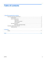
Table of contents 1 Removal and replacement procedures Preliminary replacement requirements 2 Tools required ...2 Service considerations ...2 Plastic parts ...2 Cables and connectors 3 Drive handling ...3 Grounding guidelines ...4 Electrostatic discharge damage 4 Component replacement procedures - HP Presario CQ45-200 | Compaq Presario CQ45 Notebook PC - Display Replacement Gu - Page 4
iv ENWW - HP Presario CQ45-200 | Compaq Presario CQ45 Notebook PC - Display Replacement Gu - Page 5
1 Removal and replacement procedures ENWW 1 - HP Presario CQ45-200 | Compaq Presario CQ45 Notebook PC - Display Replacement Gu - Page 6
● Phillips P0 and P1 screwdrivers Service considerations The following sections include some of you must keep in mind during disassembly and assembly procedures. NOTE: As prevent damage. Plastic parts Using excessive force during disassembly and reassembly can damage plastic parts. Use care - HP Presario CQ45-200 | Compaq Presario CQ45 Notebook PC - Display Replacement Gu - Page 7
Cables and connectors CAUTION: When servicing the computer, be sure that cables are placed in their proper locations during the reassembly process. Improper cable placement can damage the computer. Cables must - HP Presario CQ45-200 | Compaq Presario CQ45 Notebook PC - Display Replacement Gu - Page 8
Grounding guidelines Electrostatic discharge damage Electronic components are sensitive to electrostatic discharge (ESD). Circuitry design and structure determine the degree of sensitivity. Networks built into many integrated circuits provide some protection, but in many cases, ESD contains enough - HP Presario CQ45-200 | Compaq Presario CQ45 Notebook PC - Display Replacement Gu - Page 9
unplugging the AC adapter from the computer. 4. Turn the computer upside down on a flat surface. 5. Slide the battery release latch (1) to release the battery. 6. Pivot the battery (2) upward and lift it out of the computer (3). 7. Position the computer with the right side toward you. 8. Remove - HP Presario CQ45-200 | Compaq Presario CQ45 Notebook PC - Display Replacement Gu - Page 10
10. Use the media tray frame to remove the optical drive (3). 11. If it is necessary to replace the optical drive bracket, position the optical drive with the optical drive bracket toward you. 12. Remove the two Phillips PM2.0×3.0 screws (1) that secure the optical drive bracket to the optical - HP Presario CQ45-200 | Compaq Presario CQ45 Notebook PC - Display Replacement Gu - Page 11
by the governmental agency that regulates wireless devices in your country or region. If you replace the module and then receive a warning message, remove the module to restore computer functionality, and then contact technical support through Help and Support. NOTE: WLAN modules are designed with - HP Presario CQ45-200 | Compaq Presario CQ45 Notebook PC - Display Replacement Gu - Page 12
the RTC battery (2). NOTE: Removing the RTC battery and leaving it uninstalled for 5 or more minutes causes all passwords and CMOS settings to be cleared. 22. Turn the computer upside down, with the front toward you. 23. Remove the three Phillips PM2.5×17.0 screws that secure the keyboard to the - HP Presario CQ45-200 | Compaq Presario CQ45 Notebook PC - Display Replacement Gu - Page 13
(2) up until the tabs on the bottom of the keyboard are clear of the switch cover. 29. Release the zero insertion force (ZIF) connector (1) to which the keyboard cable is attached and disconnect the keyboard cable (2) from the system board. 30. Turn the computer upside down, with the rear toward - HP Presario CQ45-200 | Compaq Presario CQ45 Notebook PC - Display Replacement Gu - Page 14
PM2.5×10.0 screws (1), the Phillips PM2.0x2.0 broad head screw (2) from the optical drive bay, and the four Phillips PM2.0x4.0 screws (3) from the battery bay that secure the switch cover to the computer. 32. Turn the computer display-side up, with the front toward you. 33. Open the computer - HP Presario CQ45-200 | Compaq Presario CQ45 Notebook PC - Display Replacement Gu - Page 15
39. Remove the wireless antenna cables (1) from the hole in the system board and the routing channels built into the top cover. 40. Disconnect the display panel cable (2). CAUTION: Support the display assembly when removing the following screws. Failure to support the display assembly can result in - HP Presario CQ45-200 | Compaq Presario CQ45 Notebook PC - Display Replacement Gu - Page 16
43. If it is necessary to replace any of the display assembly internal components, remove the following screw covers and screws. The display rubber screw covers are included in the Rubber Display Kit, spare part number 486731-001. (1) Two rubber screw covers on the display bezel bottom edge (2) Two - HP Presario CQ45-200 | Compaq Presario CQ45 Notebook PC - Display Replacement Gu - Page 17
47. Disconnect the display panel cable (2) and the backlight cable (3) from the display inverter. The display inverter is available using spare part number 486736-001. 48. Remove the inverter. 49. If it is necessary to replace the display panel, remove the six black Phillips PM2.5×5.0 screws (1) - HP Presario CQ45-200 | Compaq Presario CQ45 Notebook PC - Display Replacement Gu - Page 18
display hinges (2) from the display. The display hinges are available using spare part number 486737-001. 53. If it is necessary to replace the wireless antenna transceivers and cables, remove the Phillips PM2.5×4.0 screw (1) that secures each transceiver to the display enclosure. 54. Detach the - HP Presario CQ45-200 | Compaq Presario CQ45 Notebook PC - Display Replacement Gu - Page 19
antenna transceivers and cables (4) from the display enclosure. The wireless antenna transceivers and cables are included in the Wireless Antenna Kit, spare part number 489066-001. Reverse this procedure to reassemble and install the display assembly. ENWW Component replacement procedures 15 - HP Presario CQ45-200 | Compaq Presario CQ45 Notebook PC - Display Replacement Gu - Page 20
16 Chapter 1 Removal and replacement procedures ENWW - HP Presario CQ45-200 | Compaq Presario CQ45 Notebook PC - Display Replacement Gu - Page 21
exercised when removing these components. NOTE: Materials Disposal. This HP product contains mercury in the backlight in the display assembly that appendix are general disassembly instructions. Specific details, such as screw sizes, quantities, and locations, and component shapes and sizes, can vary - HP Presario CQ45-200 | Compaq Presario CQ45 Notebook PC - Display Replacement Gu - Page 22
Perform the following steps to disassemble the display assembly: 1. Remove all screw covers (1) and screws (2) that secure the display bezel to the display assembly. 2. Lift up and out on the left - HP Presario CQ45-200 | Compaq Presario CQ45 Notebook PC - Display Replacement Gu - Page 23
4. Disconnect all display panel cables (1) from the display inverter and remove the inverter (2). 5. Remove all screws (1) that secure the display panel assembly to the display enclosure. 6. Remove the display panel assembly (2) from the display enclosure. 7. Turn the display panel assembly upside - HP Presario CQ45-200 | Compaq Presario CQ45 Notebook PC - Display Replacement Gu - Page 24
10. Remove the display panel frame (2) from the display panel. 11. Remove the screws (1) that secure the backlight cover to the display panel. 12. Lift the top edge of the backlight cover (2) and swing it outward. 13. Remove the backlight cover. 14. Turn the display panel right-side up. 20 Chapter - HP Presario CQ45-200 | Compaq Presario CQ45 Notebook PC - Display Replacement Gu - Page 25
15. Remove the backlight cables (1) from the clip (2) in the display panel. 16. Turn the display panel upside down. 17. Remove the backlight frame from the display panel. WARNING! The backlight contains mercury. Exercise caution when removing and handling the backlight to avoid damaging this - HP Presario CQ45-200 | Compaq Presario CQ45 Notebook PC - Display Replacement Gu - Page 26
19. Disconnect the display cable (1) from the LCD panel. 20. Remove the screws (2) that secure the LCD panel to the display rear panel. 21. Release the LCD panel (3) from the display rear panel. 22. Release the tape (4) that secures the LCD panel to the display rear panel. 23. Remove the LCD panel. - HP Presario CQ45-200 | Compaq Presario CQ45 Notebook PC - Display Replacement Gu - Page 27
13 O optical drive precautions 3 P plastic parts 2 R removal/replacement preliminaries 2 procedures 5 RTC battery compartment cover removal 7 S service considerations 2 T tools required 2 W wireless antenna removal 14 spare part number 15 Wireless Antenna Kit, spare part number 15 ENWW Index 23 - HP Presario CQ45-200 | Compaq Presario CQ45 Notebook PC - Display Replacement Gu - Page 28
24 Index ENWW - HP Presario CQ45-200 | Compaq Presario CQ45 Notebook PC - Display Replacement Gu - Page 29
- HP Presario CQ45-200 | Compaq Presario CQ45 Notebook PC - Display Replacement Gu - Page 30
-
 1
1 -
 2
2 -
 3
3 -
 4
4 -
 5
5 -
 6
6 -
 7
7 -
8
-
9
-
10
-
11
-
12
-
13
-
14
-
15
-
16
-
17
-
18
-
19
-
20
-
21
-
22
-
23
-
24
-
25
-
26
-
27
-
28
-
29
-
30
 |
 |

Compaq Presario CQ45 Notebook PC
Display Replacement Guide