HP Pro 2000 Maintenance & Service Guide: HP Pro 2000/2080 Business PC
HP Pro 2000 - Microtower PC Manual
 |
View all HP Pro 2000 manuals
Add to My Manuals
Save this manual to your list of manuals |
HP Pro 2000 manual content summary:
- HP Pro 2000 | Maintenance & Service Guide: HP Pro 2000/2080 Business PC - Page 1
Maintenance & Service Guide HP Pro 2000 Business PCs HP Pro 2080 Business PCs - HP Pro 2000 | Maintenance & Service Guide: HP Pro 2000/2080 Business PC - Page 2
. No part of this document may be photocopied, reproduced, or translated to another language without the prior written consent of Hewlett-Packard Company. Maintenance & Service Guide HP Pro 2000 Business PCs HP Pro 2080 Business PCs First Edition (November 2009) Document Part Number: 597664-001 - HP Pro 2000 | Maintenance & Service Guide: HP Pro 2000/2080 Business PC - Page 3
About This Book WARNING! Text set off in this manner indicates that failure to follow directions could result in bodily harm or loss of life. CAUTION: Text set off in this manner indicates that failure to follow directions could result in damage to equipment or loss of information. NOTE: Text set - HP Pro 2000 | Maintenance & Service Guide: HP Pro 2000/2080 Business PC - Page 4
iv About This Book - HP Pro 2000 | Maintenance & Service Guide: HP Pro 2000/2080 Business PC - Page 5
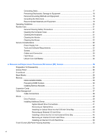
Components ...5 2 Installing and Customizing the Software ...6 Installing the Operating System ...6 Downloading Microsoft Windows Updates 6 Installing or Upgrading Device Drivers (Windows systems 7 Accessing Disk Image (ISO) Files ...7 Protecting the Software ...7 3 Computer Setup (F10) Utility - HP Pro 2000 | Maintenance & Service Guide: HP Pro 2000/2080 Business PC - Page 6
...22 Cleaning the Mouse ...22 Service Considerations ...22 Power Supply Fan ...22 Tools and Software Requirements 22 Screws ...23 Cables and Connectors ...23 Hard Drives ...23 Lithium Coin Cell Battery 24 6 Removal and Replacement Procedures Microtower (MT) Chassis 25 Preparation for Disassembly - HP Pro 2000 | Maintenance & Service Guide: HP Pro 2000/2080 Business PC - Page 7
...56 Processor ...57 Power Supply ...58 System Board ...60 Battery ...61 Type 1 Battery Holder ...62 Type 2 Battery Holder ...62 Type 3 Battery Holder ...63 Installing a Security Lock ...64 HP/Kensington MicroSaver Security Cable Lock 64 Padlock ...64 HP Business PC Security Lock 65 Hood Sensor - HP Pro 2000 | Maintenance & Service Guide: HP Pro 2000/2080 Business PC - Page 8
Front Panel Component Problems 105 Solving Internet Access Problems ...106 Solving Software Problems ...108 Interpreting Power LED and Beep Codes 109 Resetting the Password Jumper ...110 Resetting the CMOS Jumper ...111 Contacting Customer Support ...112 Appendix D Specifications ...113 Index - HP Pro 2000 | Maintenance & Service Guide: HP Pro 2000/2080 Business PC - Page 9
HP Pro Business PC features may vary depending on the model. For a complete listing of the hardware and software installed in the computer, run the diagnostic utility (included on some computer models only). Instructions for using the utility are provided in the Troubleshooting Guide. Figure 1-1 HP - HP Pro 2000 | Maintenance & Service Guide: HP Pro 2000/2080 Business PC - Page 10
Figure 1-2 HP Pro 2080 NOTE: The drive configuration shown above may be different than your computer model. Serviceability Features The Microtower computer includes features that make it easy to upgrade and service. A Torx T-15 or flat blade screwdriver is needed for many of the installation - HP Pro 2000 | Maintenance & Service Guide: HP Pro 2000/2080 Business PC - Page 11
Drive Eject Button 3 3.5-inch Media Card Reader (optional)2 8 Microphone Connector 4 Recovery/Reset Button 9 Headphone Connector 5 Dual-State Power Button 10 USB (Universal Serial Bus) 2.0 Ports 1 Some models have bezel blanks covering one or both of the 5.25-inch drive bays. 2 Some - HP Pro 2000 | Maintenance & Service Guide: HP Pro 2000/2080 Business PC - Page 12
models miniSD ● Secure Digital (SD) ● Secure Digital PRO/MS PRO DUO ● Memory Stick (MS) ● Memory Stick Select ● Memory Stick PRO ● MagicGate Memory Stick (MG) ● Memory Stick Duo (MS Duo) Duo (MS PRO Duo) ● Memory Stick PRO- ● MagicGate Memory Duo ● Memory Stick PRO (MS PRO) HG Duo ● Memory - HP Pro 2000 | Maintenance & Service Guide: HP Pro 2000/2080 Business PC - Page 13
by model. When a device is plugged into the blue Line-In Audio Connector, a dialog box will pop up asking if you want to use the connector for a line-in device or a microphone. You can reconfigure the connector at any time by double-clicking the Realtek HD Audio Manager icon in the Windows taskbar - HP Pro 2000 | Maintenance & Service Guide: HP Pro 2000/2080 Business PC - Page 14
information is available in online help after you install the operating system. Downloading Microsoft Windows Updates 1. To set up your Internet connection, click Start > Internet Explorer and follow the instructions on the screen. 2. Once an Internet connection has been established, click - HP Pro 2000 | Maintenance & Service Guide: HP Pro 2000/2080 Business PC - Page 15
operating system from http://www.hp.com/support. Select your country and language, select Download drivers and software (and firmware), enter the model number of the computer, and press Enter. Accessing Disk Image (ISO) Files There are disk image files (ISO files) included on your PC that contain - HP Pro 2000 | Maintenance & Service Guide: HP Pro 2000/2080 Business PC - Page 16
Utility to do the following: ● Change factory default settings. ● Set the system date and time. ● Set, view, change, or verify the system configuration, including settings for processor, graphics, memory, audio, storage, communications, and input devices. ● Modify the boot order of bootable devices - HP Pro 2000 | Maintenance & Service Guide: HP Pro 2000/2080 Business PC - Page 17
Heading Table Main Computer Setup-Main on page 10 Advanced Computer Setup-Advanced on page 11 Boot Computer Setup-Boot on page 12 Power Computer Setup-Power on page 13 PC Health Computer Setup-PC Health on page 13 Exit Computer Setup-Exit on page 14 Computer Setup (F10) Utilities 9 - HP Pro 2000 | Maintenance & Service Guide: HP Pro 2000/2080 Business PC - Page 18
Support for specific Computer Setup options may vary depending on the hardware configuration. Table 3-2 Computer Setup-Main Option Description System only) ● Cache Size (view only) ● Memory Size (view only) ● Integrated MAC (view only) ● System BIOS (view only) ● Chassis Serial Number (view only - HP Pro 2000 | Maintenance & Service Guide: HP Pro 2000/2080 Business PC - Page 19
seconds Computer Setup-Advanced NOTE: Support for specific Computer Setup options may vary depending PCI Slot ● PCIEx MAX DVMT Allocation Allows you to specify the DVMT/system memory allocated for video memory.: ● 128MB ● 256MB ● Max Onboard HD Audio Allows you to disable/enable onboard audio - HP Pro 2000 | Maintenance & Service Guide: HP Pro 2000/2080 Business PC - Page 20
● 3E8/IRQ4 ● 2E8/IRQ3 Computer Setup-Boot NOTE: Support for specific Computer Setup options may vary depending on the hardware configuration. Table drives (including USB ODD) are checked for a bootable operating system image. Allows you to specify the order in which network devices (including - HP Pro 2000 | Maintenance & Service Guide: HP Pro 2000/2080 Business PC - Page 21
from S5 RTC Alarm Resume Allows you to select system power loss behavior: ● Off ● On ● Last State Disables/enables waking up from S5 by PCI device. Disables/enables RTC (real-time clock) alarm. Computer Setup-PC Health NOTE: Support for specific Computer Setup options may vary depending on the - HP Pro 2000 | Maintenance & Service Guide: HP Pro 2000/2080 Business PC - Page 22
Table 3-6 Computer Setup-PC Health (continued) Option Description Current CPU Fan Speed (view only) Current System Fan Speed (view only) Computer Setup-Exit Table 3-7 Computer Setup-Exit Option Description Save Changes and Exit Allows you to save current settings and exit - HP Pro 2000 | Maintenance & Service Guide: HP Pro 2000/2080 Business PC - Page 23
Drive Guidelines and Features NOTE: HP only supports the use of SATA hard drives on these models of computer. No Parallel ATA (PATA) drives are supported. SATA Hard Drives Serial ATA Hard Drive Characteristics Number of pins/conductors in data cable Number of pins in power cable Maximum data cable - HP Pro 2000 | Maintenance & Service Guide: HP Pro 2000/2080 Business PC - Page 24
HP specification. Drive size calculations by drive manufacturers are bytes to the base 10 while calculations by Microsoft are bytes to the base 2. File System FAT 32 NTFS Controller Type ATA ATA Drive/Partition Capacity Limits Operating System Windows XP/Windows Vista/Windows 7 Windows XP/Windows - HP Pro 2000 | Maintenance & Service Guide: HP Pro 2000/2080 Business PC - Page 25
this chapter is essential for proper service. CAUTION: When the computer is plugged into an AC power source, voltage is always applied to the system board. You must disconnect the power cord from the power source before opening the computer to prevent system board or component damage. Electrostatic - HP Pro 2000 | Maintenance & Service Guide: HP Pro 2000/2080 Business PC - Page 26
Removing DIPs* from vinyl tray 2,000 V Removing DIPs* from Styrofoam 3,500 V Removing bubble pack from PCB 7,000 V Packing PCBs in foam-lined box 5,000 V *These are then multi-packaged inside plastic tubes, trays, or Styrofoam. 4,000 V 5,000 V 20,000 V 11,000 V 11,500 V 14,500 V 26,500 V - HP Pro 2000 | Maintenance & Service Guide: HP Pro 2000/2080 Business PC - Page 27
. Handle them only at static-free work areas. ● Turn off power and input signals before inserting and removing connectors or test equipment. ● Static-dissipative table or floor mats with hard tie to ground ● Field service kits ● Static awareness labels ● Wrist straps and footwear straps providing - HP Pro 2000 | Maintenance & Service Guide: HP Pro 2000/2080 Business PC - Page 28
the keyboard, with the keyboard feet down, directly against the front of the desktop unit as this also restricts airflow. ● Occasionally clean the air vents on all type of material. ● Install or enable power management functions of the operating system or other software, including sleep states. 20 - HP Pro 2000 | Maintenance & Service Guide: HP Pro 2000/2080 Business PC - Page 29
Routine Care General Cleaning Safety Precautions 1. Never use solvents or flammable solutions to clean the computer. 2. Never immerse any parts in water or cleaning solutions; apply any liquids to a clean cloth and then use the cloth on the component. 3. Always unplug the computer when cleaning with - HP Pro 2000 | Maintenance & Service Guide: HP Pro 2000/2080 Business PC - Page 30
or "Off" modes. You must disconnect the power cord from the power source before opening the computer to prevent system board or component damage. Tools and Software Requirements To service the computer, you need the following: ● Torx T-15 screwdriver (HP screwdriver with bits, PN 161946-001) ● Torx - HP Pro 2000 | Maintenance & Service Guide: HP Pro 2000/2080 Business PC - Page 31
it can damage the unit. HP strongly recommends that all screws removed Apply only the tension required to seat or unseat the cables during or replaced. CAUTION: When servicing this computer, ensure that their protective packaging until they are actually mounted in the CPU. ● Avoid dropping drives - HP Pro 2000 | Maintenance & Service Guide: HP Pro 2000/2080 Business PC - Page 32
power to the real-time clock and has a minimum lifetime of about three years. See the appropriate removal and replacement chapter for the chassis you are working on in this guide for instructions , please use the public collection system or return them to HP, their authorized partners, or their - HP Pro 2000 | Maintenance & Service Guide: HP Pro 2000/2080 Business PC - Page 33
present on the system board as long as the system is plugged into an active AC outlet. In some systems the cooling fan is on even when the computer is in the "Standby," or "Suspend" modes. The power cord should always be disconnected before servicing a unit. 5. Disconnect the power cord from the - HP Pro 2000 | Maintenance & Service Guide: HP Pro 2000/2080 Business PC - Page 34
the computer for disassembly (Preparation for Disassembly on page 25). 2. Loosen the screw (1) that secures the access panel to the computer chassis. 3. Slide the access panel back (2) about 1.3 cm reverse the removal steps. 26 Chapter 6 Removal and Replacement Procedures Microtower (MT) Chassis - HP Pro 2000 | Maintenance & Service Guide: HP Pro 2000/2080 Business PC - Page 35
Front Bezel 1. Prepare the computer for disassembly (Preparation for Disassembly on page 25). 2. Remove the access panel (Access Panel on page 26). 3. Press outward on the three latches on the right side of the bezel (1), then rotate the right side of the bezel off the chassis (2) followed by the - HP Pro 2000 | Maintenance & Service Guide: HP Pro 2000/2080 Business PC - Page 36
Bezel Blanks On some models, there are bezel blanks covering blank needs to be replaced at a later date, you can order a replacement blank from HP. 3. To remove the 3.5-inch bezel blank, press the two retaining tabs towards the outer Chapter 6 Removal and Replacement Procedures Microtower (MT) Chassis - HP Pro 2000 | Maintenance & Service Guide: HP Pro 2000/2080 Business PC - Page 37
are populated with at least one preinstalled DIMM. To achieve the maximum memory support, you can populate the system board with up to 8 GB of memory configured in a highperforming dual channel mode. For proper system operation, the DDR3-SDRAM DIMMs must be: ● industry-standard 240-pin ● unbuffered - HP Pro 2000 | Maintenance & Service Guide: HP Pro 2000/2080 Business PC - Page 38
● The system will operate in a higher-performing dual channel mode if the total memory capacity of the DIMMs in Channel A is equal to the total memory capacity of one 2-GB DIMM, the system will operate in dual channel mode. 30 Chapter 6 Removal and Replacement Procedures Microtower (MT) Chassis - HP Pro 2000 | Maintenance & Service Guide: HP Pro 2000/2080 Business PC - Page 39
speed is determined by the slowest DIMM in the system. Installing Memory Modules CAUTION: You must disconnect the power cord and wait approximately 30 seconds for the power to drain before adding or removing memory modules. Regardless of the power-on state, voltage is always supplied to the - HP Pro 2000 | Maintenance & Service Guide: HP Pro 2000/2080 Business PC - Page 40
seated. The DIMM must be pushed all the way down into the socket and sit evenly in the socket to avoid memory memory when you turn on the computer. 9. Lock any security devices that were disengaged when the access panel was removed. 32 Chapter 6 Removal and Replacement Procedures Microtower (MT - HP Pro 2000 | Maintenance & Service Guide: HP Pro 2000/2080 Business PC - Page 41
Expansion Cards The HP Pro 2000/2080 has two PCI expansion slots, one PCI Express x1 expansion slot, and one PCI Express x16 expansion slot. The expansion slots accommodate full-height or half-height expansion cards. Figure 6-6 Expansion Slot Locations Table 6-2 Expansion Slot Locations Item - HP Pro 2000 | Maintenance & Service Guide: HP Pro 2000/2080 Business PC - Page 42
4. On the rear of the computer, a slot cover lock secures the expansion card brackets in place. Remove the screw from the slot cover lock then slide expansion card you are installing. Figure 6-8 Removing an Expansion Slot Cover 34 Chapter 6 Removal and Replacement Procedures Microtower (MT) Chassis - HP Pro 2000 | Maintenance & Service Guide: HP Pro 2000/2080 Business PC - Page 43
to release it from the chassis frame. Be sure not to scrape the card against the other components. Figure 6-9 Removing a PCI or PCI Express x1 Expansion Card c. If you are removing a PCI Express x16 card, pull the retention arm on the back of the expansion socket away from the card and carefully - HP Pro 2000 | Maintenance & Service Guide: HP Pro 2000/2080 Business PC - Page 44
socket on the system board then move seats properly in the expansion card slot. 9. Replace the slot cover lock and secure it in place with the screw that was previously removed. Figure 6-12 Securing the Expansion Cards and Slot Covers 36 Chapter 6 Removal and Replacement Procedures Microtower (MT - HP Pro 2000 | Maintenance & Service Guide: HP Pro 2000/2080 Business PC - Page 45
. 12. Reconnect the power cord and any external devices, then turn on the computer. 13. Lock any security devices that were disengaged when the access panel was removed. 14. Reconfigure the computer, if necessary. Refer to the Computer Setup (F10) Utility Guide for instructions on using Computer - HP Pro 2000 | Maintenance & Service Guide: HP Pro 2000/2080 Business PC - Page 46
pull the connector - NEVER pull on the cable. Pulling on the cable could damage the cable and result in a failed power supply. Cable Connections System board connectors are color-coded to make it easier to find the proper connection. Connector Name PWR PWRCPU CHFAN1 CPUFAN MEDIA SPKR JFP1 FRNT AUD - HP Pro 2000 | Maintenance & Service Guide: HP Pro 2000/2080 Business PC - Page 47
Drives The computer supports up to five drives that may be installed in various configurations. This section describes the procedure for replacing or upgrading the storage drives. A Torx T-15 screwdriver is needed to remove and install the guide screws on a drive. Drive Positions NOTE: Front bezel - HP Pro 2000 | Maintenance & Service Guide: HP Pro 2000/2080 Business PC - Page 48
system does not support Parallel ATA (PATA) optical drives or PATA hard drives. ● If needed, HP has provided extra drive retainer screws on the interior of the front bezel that are used to secure the operating system properly, turn off the computer, and unplug the power cord. Microtower (MT) Chassis - HP Pro 2000 | Maintenance & Service Guide: HP Pro 2000/2080 Business PC - Page 49
board drive connectors. Figure 6-15 System Board Drive Connections Table 6-3 System Board Drive Connections No. System Board Connector System Board Label 1 SATA1 SATA1 2 SATA2 SATA2 3 SATA3 SATA3 4 SATA4 SATA4 5 Media Card Reader MEDIA Color dark blue white light blue orange - HP Pro 2000 | Maintenance & Service Guide: HP Pro 2000/2080 Business PC - Page 50
drive. Figure 6-16 Disconnecting the Power and Data Cables 5. Remove the two screws that secure the drive to the drive cage (1), then slide the drive out of the front of the chassis (2). Figure 6-17 Removing the Optical Drive 42 Chapter 6 Removal and Replacement Procedures Microtower (MT) Chassis - HP Pro 2000 | Maintenance & Service Guide: HP Pro 2000/2080 Business PC - Page 51
for an illustration of the retainer screws location. Figure 6-18 Installing the Optical Drive 8. If the system configuration includes only one optical drive, connect the SATA data cable to the white system board connector labeled SATA2. If you are adding a second optical drive, connect the SATA data - HP Pro 2000 | Maintenance & Service Guide: HP Pro 2000/2080 Business PC - Page 52
you are removing a diskette drive (available on some models only), disconnect the data cable and power cable from the back of the drive. b. If you are removing a media card reader, disconnect the USB cable from the system board. 44 Chapter 6 Removal and Replacement Procedures Microtower (MT) Chassis - HP Pro 2000 | Maintenance & Service Guide: HP Pro 2000/2080 Business PC - Page 53
5. Remove the two retainer screws that secure the drive to the bay (1) then slide the drive forward and out of the bay (2). Figure 6-20 Removing a 3.5-inch Device (Media Card Reader Shown) Installing a - HP Pro 2000 | Maintenance & Service Guide: HP Pro 2000/2080 Business PC - Page 54
the USB cable from the media card reader to the USB connector on the system board. 9. Replace the front bezel and access panel. 10. Reconnect the power cord and turn on the computer. 11. Lock any security devices that were disengaged when the access panel was removed. Removing an Internal 3.5-inch - HP Pro 2000 | Maintenance & Service Guide: HP Pro 2000/2080 Business PC - Page 55
3. Remove the two screws that secure the hard drive cage to the chassis. Figure 6-22 Removing the Hard Drive Cage Screws 4. Push down the latch on the side of the hard - HP Pro 2000 | Maintenance & Service Guide: HP Pro 2000/2080 Business PC - Page 56
5. Lift the hard drive cage out of the chassis. Figure 6-24 Removing the Hard Drive Cage 6. Disconnect the power cable (1) and data cable (2) from the back of the hard drive. Figure 6-25 Disconnecting the Hard Drive Cables 48 Chapter 6 Removal and Replacement Procedures Microtower (MT) Chassis - HP Pro 2000 | Maintenance & Service Guide: HP Pro 2000/2080 Business PC - Page 57
7. Remove the four screws that secure the hard disk drive to the hard drive cage (1), then slide the hard disk drive out of the hard drive cage (2). Figure 6-26 Removing the - HP Pro 2000 | Maintenance & Service Guide: HP Pro 2000/2080 Business PC - Page 58
aligning the drive with the four screw holes on the cage. Install the four 6-32 standard screws that secure the hard disk drive to the hard disk drive cage (2). Make sure the hard disk drive cables are Drive in the Drive Cage 50 Chapter 6 Removal and Replacement Procedures Microtower (MT) Chassis - HP Pro 2000 | Maintenance & Service Guide: HP Pro 2000/2080 Business PC - Page 59
3. Connect the power cable (1) and data cable (2) to the back of the hard drive. Figure 6-28 Connecting the Hard Drive Cables CAUTION: Never crease or bend a SATA data - HP Pro 2000 | Maintenance & Service Guide: HP Pro 2000/2080 Business PC - Page 60
on the system board. 7. Replace the computer access panel. 8. Reconnect the power cord and any external devices, then turn on the computer. 9. Lock any security devices that were disengaged when the access panel was removed. 52 Chapter 6 Removal and Replacement Procedures Microtower (MT) Chassis - HP Pro 2000 | Maintenance & Service Guide: HP Pro 2000/2080 Business PC - Page 61
. The assembly cables connect to the following system board connectors: ● F_AUDIO - yellow ● F_USB1 - white 6. Remove the screw (1) that secures the housing to the chassis, slide the housing up (2), and then pull the assembly away from the chassis while guiding the cables through the hole in the - HP Pro 2000 | Maintenance & Service Guide: HP Pro 2000/2080 Business PC - Page 62
braided cables from the black system board connector labeled JFP1. 7. power switch away from the chassis while guiding the wires through the hole in the chassis. To install the power switch/LED assembly, reverse the removal procedures. 54 Chapter 6 Removal and Replacement Procedures Microtower (MT - HP Pro 2000 | Maintenance & Service Guide: HP Pro 2000/2080 Business PC - Page 63
26). 3. Lay the computer on its side with the rear facing toward you. 4. Disconnect the cable from the red/brown system board connector labeled CH_FAN1. 5. Remove the four Phillips screws that secure the fan to the chassis, rotate the top of the fan forward, and then remove the fan from the chassis - HP Pro 2000 | Maintenance & Service Guide: HP Pro 2000/2080 Business PC - Page 64
(2) from the white system board connector labeled CPUFAN. NOTE: System board appearance may vary. 6. Lift the heat sink from the processor and set it on its side to keep from contaminating the work area with thermal grease. 56 Chapter 6 Removal and Replacement Procedures Microtower (MT) Chassis - HP Pro 2000 | Maintenance & Service Guide: HP Pro 2000/2080 Business PC - Page 65
be tightened in diagonally opposite pairs (as in an X) to evenly seat the heat sink to the processor. This is especially important as the pins on the socket are very fragile and any damage to them may require replacing the system board. When reinstalling an existing heat sink, make sure that its - HP Pro 2000 | Maintenance & Service Guide: HP Pro 2000/2080 Business PC - Page 66
Secure the heat sink to the system board and system board tray with the system board, always update the system ROM to ensure that the latest version of the BIOS is being used on the computer. The latest system ROM BIOS can be found on the Web at: http:\\h18000.www1.hp.com/support/files. Power - HP Pro 2000 | Maintenance & Service Guide: HP Pro 2000/2080 Business PC - Page 67
the four screws that secure the power supply to the chassis. 6. Inside of the unit, press the power supply release latch on the chassis base, and then lift up the rear of the power supply to disengage it from the chassis. NOTE: System board appearance may vary. 7. Slide the power supply toward the - HP Pro 2000 | Maintenance & Service Guide: HP Pro 2000/2080 Business PC - Page 68
system board. 8. Remove the eight screws that secure the system board to the chassis. NOTE: System board appearance varies by model. 9. Slide the system board toward the front of the chassis, and then lift it up and out of the chassis. 60 Chapter 6 Removal and Replacement Procedures Microtower (MT - HP Pro 2000 | Maintenance & Service Guide: HP Pro 2000/2080 Business PC - Page 69
installing a new system board, always update the system ROM to ensure that the latest version of the BIOS is being used on the computer. The latest system ROM BIOS can be found at: http:\\h18000.www1.hp.com/support/files. Battery The battery that comes with your computer provides power to the real - HP Pro 2000 | Maintenance & Service Guide: HP Pro 2000/2080 Business PC - Page 70
automatically secures the battery in the proper position. 4. Replace the computer access panel. 5. Plug in the computer and turn on power to the computer. 6. Reset the date and time, your passwords, and any special system setups, using Computer Setup. Refer to the Computer Setup (F10) Utility Guide - HP Pro 2000 | Maintenance & Service Guide: HP Pro 2000/2080 Business PC - Page 71
4. Plug in the computer and turn on power to the computer. 5. Reset the date and time, your passwords, and any special system setups, using Computer Setup. Refer to the Computer Setup (F10) Utility Guide. Type 3 Battery Holder 1. Pull back on the clip (1) that holds the battery in place, then remove - HP Pro 2000 | Maintenance & Service Guide: HP Pro 2000/2080 Business PC - Page 72
a Security Lock The security locks displayed below and on the following pages can be used to secure the computer. HP/Kensington MicroSaver Security Cable Lock Figure 6-31 Installing a Cable Lock Padlock Figure 6-32 Installing a Padlock 64 Chapter 6 Removal and Replacement Procedures Microtower (MT - HP Pro 2000 | Maintenance & Service Guide: HP Pro 2000/2080 Business PC - Page 73
HP Business PC Security Lock 1. Fasten the security cable by looping it around a stationary object. Figure 6-33 Securing the Cable to a Fixed Object 2. Thread the keyboard and mouse cables through the lock. Figure 6-34 Threading the Keyboard and Mouse Cables Installing a Security Lock 65 - HP Pro 2000 | Maintenance & Service Guide: HP Pro 2000/2080 Business PC - Page 74
3. Screw the lock to the chassis using the screw provided. Figure 6-35 Attaching the Lock to the Chassis 4. Insert the plug end of the security cable into the lock (1) and push the button in (2) to engage the lock. Use the key provided to disengage the lock. Figure 6-36 Engaging the - HP Pro 2000 | Maintenance & Service Guide: HP Pro 2000/2080 Business PC - Page 75
, press the F10 key immediately when the HP Logo screen is displayed to enter the Computer Setup menu. In the menu, select Advanced > Hood Sensor > Reset Case Open Status and make sure Enable is selected, then press the F10 key to Save and Exit, then reboot the system. Installing a Security Lock 67 - HP Pro 2000 | Maintenance & Service Guide: HP Pro 2000/2080 Business PC - Page 76
HP Chassis Security Kit An optional HP Chassis Security Kit prevents computer components from being removed through an open optical drive bay. Figure 6-37 HP Chassis Security Kit Figure 6-38 Installing the HP Chassis Security Kit 68 Chapter 6 Removal and Replacement Procedures Microtower (MT) - HP Pro 2000 | Maintenance & Service Guide: HP Pro 2000/2080 Business PC - Page 77
the pin assignments for many computer and workstation connectors. Some of these connectors may not be used on the product being serviced. Ethernet BNC Connector and Icon Pin Signal 1 Data 2 Ground USB Connector and Icon Microphone Connector and Icon (1/8" miniphone) 1 23 Pin Signal - HP Pro 2000 | Maintenance & Service Guide: HP Pro 2000/2080 Business PC - Page 78
Headphone Connector and Icon (1/8" miniphone) 1 23 Line-in Audio Connector and Icon (1/8" miniphone) 1 23 Line-out Audio Connector and Icon (1/8" miniphone) 1 23 4-Pin Power (for CPU) Connector and Icon Pin 1 (Tip) 2 (Ring) 3 (Shield) Signal Audio_left Power_Right Ground Pin 1 (Tip) 2 (Ring) 3 ( - HP Pro 2000 | Maintenance & Service Guide: HP Pro 2000/2080 Business PC - Page 79
DDC Serial Data 13 Horizontal Sync 14 Vertical Sync 15 DDC Serial Clock Serial Interface, Powered and Non-Powered Connector and Icon Pin Signal 1 Carrier Detect (12V if powered) 2 Receive Data 3 Transmit Data 4 Data Terminal Ready 5 Signal Ground 6 Data Set Ready 7 Request to - HP Pro 2000 | Maintenance & Service Guide: HP Pro 2000/2080 Business PC - Page 80
DDC Data 8 No Connect 9 T.M.D.S. Data1- 10 T.M.D.S. Data1+ 11 T.M.D.S. Data1/3 Shield 12 T.M.D.S. Data3- Pin Signal 13 T.M.D.S. Data3+ 14 +5V Power 15 Ground (for +5V) 16 Hot Pug Detect 17 T.M.D.S. Data0- 18 T.M.D.S. Data0+ 19 T.M.D.S. Data0/5 Shield 20 T.M.D.S. Data5- 21 - HP Pro 2000 | Maintenance & Service Guide: HP Pro 2000/2080 Business PC - Page 81
, x4, x8, and x16 PCI Express Connector Pin A Pin Signal Pin Signal 1 PRSNT1 6 JTAG3 2 +12V 7 JTAG4 3 + B information is on the next page NOTE: x1 PCI Express uses pins 1-18 x4 PCI Express uses pins 1-32 x8 PCI Express uses pins 1-49 x16 PCI Express uses pins 1-8 Pin Signal 11 PERST# 12 - HP Pro 2000 | Maintenance & Service Guide: HP Pro 2000/2080 Business PC - Page 82
, x4, x8, and x16 PCI Express Connector Pin B Pin Signal Pin Signal 1 +12V 6 SMDAT 2 +12V 7 GND 3 RSVD 8 B information is on the next page NOTE: x1 PCI Express uses pins 1-18 x4 PCI Express uses pins 1-32 x8 PCI Express uses pins 1-49 x16 PCI Express uses pins 1-8 Pin Signal 11 WAKE# 12 - HP Pro 2000 | Maintenance & Service Guide: HP Pro 2000/2080 Business PC - Page 83
must have a minimum current capacity of 10A (7A Japan only) and a nominal voltage rating of 125 or 250 volts AC, as required by each country's power system. 3. The diameter of the wire must be a minimum of 0.75 mm2 or 18AWG, and the length of the cord must be between 1.8 m (6 feet) and 3.6 m (12 - HP Pro 2000 | Maintenance & Service Guide: HP Pro 2000/2080 Business PC - Page 84
Requirements Additional requirements specific to a country are shown in parentheses and explained below. Country cord must be Type HO5VV-F, 3-conductor, 0.75mm2 conductor size. Power cord set fittings (appliance coupler and wall plug) must bear the certification mark of the agency responsible for - HP Pro 2000 | Maintenance & Service Guide: HP Pro 2000/2080 Business PC - Page 85
to the Safe Mode to see if it will boot without all of the drivers loaded. When booting the operating system, use "Last Known Configuration." ● Refer to the comprehensive online technical support at http://www.hp.com/support. ● Refer to Helpful Hints on page 78 in this guide. Safety and Comfort 77 - HP Pro 2000 | Maintenance & Service Guide: HP Pro 2000/2080 Business PC - Page 86
serial number, product ID number, and monitor serial number before calling. ● Spend time troubleshooting the problem with the service technician. ● Remove any hardware that was recently added to your system. ● Remove any software that was recently installed. NOTE: For sales information and warranty - HP Pro 2000 | Maintenance & Service Guide: HP Pro 2000/2080 Business PC - Page 87
you have installed an operating system other than the factory-installed operating system, check to be sure that it is supported on the system. ● If the system has multiple video sources (embedded, PCI, or PCI-Express adapters) installed (embedded video on some models only) and a single monitor, the - HP Pro 2000 | Maintenance & Service Guide: HP Pro 2000/2080 Business PC - Page 88
power cord from the wall outlet and allow the internal system components to cool before touching. Table C-1 Solving General Problems update the RTC date and time). If the problem persists, replace the RTC battery. See the Hardware Reference Guide for instructions Troubleshooting Without Diagnostics - HP Pro 2000 | Maintenance & Service Guide: HP Pro 2000/2080 Business PC - Page 89
the Smart Cover Lock using Computer Setup. The Smart Cover FailSafe Key, a device for manually disabling the Smart Cover Lock, is available from HP. You will need the FailSafe Key in case of forgotten password, power loss, or computer malfunction. Order PN 166527-001 for the wrench-style key or PN - HP Pro 2000 | Maintenance & Service Guide: HP Pro 2000/2080 Business PC - Page 90
the power button harness is properly connected to the system board. 3. Check that both power supply cables are properly connected to the system board. 4. Replace the power button harness. 5. Replace the power supply. 6. Replace the system board. 82 Appendix C Troubleshooting Without Diagnostics - HP Pro 2000 | Maintenance & Service Guide: HP Pro 2000/2080 Business PC - Page 91
or service provider. 1. Check that the voltage selector, located on the rear of the power supply (some models), is set to the appropriate voltage. Proper voltage setting depends on your region. 2. Open the hood and ensure the power supply cable is seated into the connector on the system board - HP Pro 2000 | Maintenance & Service Guide: HP Pro 2000/2080 Business PC - Page 92
block usage of bad sectors. If necessary, reformat the hard disk. Disk transaction problem. Cause Solution Either the directory structure is bad or there is a problem with In Microsoft Windows XP, right-click Start, click Explore, a file. and select a drive. Select File > Properties > Tools - HP Pro 2000 | Maintenance & Service Guide: HP Pro 2000/2080 Business PC - Page 93
, press the power button again. Solving Media Card Reader Problems Table C-4 Solving Media Card Reader Problems Media card will not work in a digital camera after formatting it in Microsoft Windows XP or Microsoft Windows Vista. Cause Solution By default, Windows XP and Windows Vista will - HP Pro 2000 | Maintenance & Service Guide: HP Pro 2000/2080 Business PC - Page 94
located on the bottom of the Memory Stick/PRO card is not in the locked position. Unable to access data on the media card after inserting it into a slot. Cause Solution The media card is not inserted properly, is inserted in the wrong slot, or is not supported. Ensure that the card is - HP Pro 2000 | Maintenance & Service Guide: HP Pro 2000/2080 Business PC - Page 95
Table C-5 Solving Display Problems Blank screen (no power button for more than four seconds. Otherwise, the computer will shut down and you will lose any unsaved data. Monitor settings in the computer are not compatible with the 1. In Windows XP PCI Express graphics card. Cause Solution On systems - HP Pro 2000 | Maintenance & Service Guide: HP Pro 2000/2080 Business PC - Page 96
followed by a three second pause. Cause Solution Pre-video memory error. 1. Reseat DIMMs. Power on the system. 2. Replace DIMMs one at a time to isolate the faulty module. 3. Replace third-party memory with HP memory. 4. Replace the system board. Blank screen and the computer emits two short - HP Pro 2000 | Maintenance & Service Guide: HP Pro 2000/2080 Business PC - Page 97
securely connected to the computer. 2. In a two-monitor system monitor for instructions. Image is not powered on. Cause Solution Monitor degaussing coil has been activated. None. It is normal for the degaussing coil to be activated when the monitor is powered on. Solving Display Problems - HP Pro 2000 | Maintenance & Service Guide: HP Pro 2000/2080 Business PC - Page 98
using does not support that particular symbol. Solution Use the Character Map to locate and select the appropriate symbol. Click Start > All Programs > Accessories > System Tools > Character Map. You can copy the symbol from the Character Map into a document. 90 Appendix C Troubleshooting Without - HP Pro 2000 | Maintenance & Service Guide: HP Pro 2000/2080 Business PC - Page 99
table. Table C-6 Solving Audio Problems Sound cuts in and out. Cause Solution Processor resources are being used by other open applications. Direct sound latency, common in many media player applications. Shut down all open processor-intensive applications. In Windows XP only: 1. From the - HP Pro 2000 | Maintenance & Service Guide: HP Pro 2000/2080 Business PC - Page 100
can also try recording the audio file in a compressed format. Solving Printer Problems If you encounter printer problems, see the documentation that works, reload the printer driver. Make the proper network connections to the printer. Run printer self-test. 92 Appendix C Troubleshooting Without - HP Pro 2000 | Maintenance & Service Guide: HP Pro 2000/2080 Business PC - Page 101
. Solution Reconnect all cables and check the power cord and electrical outlet. Printer prints garbled information. Cause The correct printer driver for the application is not installed. The cables may not be connected properly. Printer memory may be overloaded. Solution Install the correct - HP Pro 2000 | Maintenance & Service Guide: HP Pro 2000/2080 Business PC - Page 102
Problems Keyboard commands and typing are not recognized by the computer. Cause Solution Keyboard connector is not properly connected. Program in use has stopped responding to commands. Keyboard needs repairs. Computer is in standby mode. 1. On the Windows XP Desktop power button to resume from standby - HP Pro 2000 | Maintenance & Service Guide: HP Pro 2000/2080 Business PC - Page 103
Table C-9 Solving Mouse Problems (continued) Mouse does not respond to movement or is too slow. internal components. See the Worldwide Limited Warranty for terms and conditions. Press the power button to resume from standby mode. CAUTION: When attempting to resume from standby mode, do not - HP Pro 2000 | Maintenance & Service Guide: HP Pro 2000/2080 Business PC - Page 104
the correct memory modules and to verify the proper installation. NOTE: DIMM2 must always be installed. 2. Listen for beeps from the computer. Beeps are codes for specific problems. 3. If you still cannot resolve the issue, contact Customer Support. 96 Appendix C Troubleshooting Without Diagnostics - HP Pro 2000 | Maintenance & Service Guide: HP Pro 2000/2080 Business PC - Page 105
with HP memory. 4. Replace the system board. The computer emits two short beeps then one long beep followed by a three second pause. Cause Solution Graphics card is not seated properly or is bad, or system board is bad. For systems with a graphics card: 1. Reseat the graphics card. Power on - HP Pro 2000 | Maintenance & Service Guide: HP Pro 2000/2080 Business PC - Page 106
controller in Advanced > Onboard LAN. 2. Enable the network controller in the operating system via Device Manager. Check the network controller documentation for the correct driver or obtain the latest driver from the manufacturer's Web site. 98 Appendix C Troubleshooting Without Diagnostics - HP Pro 2000 | Maintenance & Service Guide: HP Pro 2000/2080 Business PC - Page 107
network drivers. System cannot autosense the network. Disable auto-sensing capabilities and force the system into the correct operating mode. Diagnostics reports a failure. Cause The cable is not securely connected. The cable is attached to the incorrect connector. There is a problem with - HP Pro 2000 | Maintenance & Service Guide: HP Pro 2000/2080 Business PC - Page 108
, that a DHCP Server is present, and that the Remote System Installation Server contains the NIC drivers for your NIC. System setup utility reports unprogrammed EEPROM. Cause Unprogrammed EEPROM. Solution Contact an authorized service provider. 100 Appendix C Troubleshooting Without Diagnostics - HP Pro 2000 | Maintenance & Service Guide: HP Pro 2000/2080 Business PC - Page 109
unplug the computer power cord before attempting to reseat, install, or remove a DIMM. For those systems that support ECC memory, HP does not support mixing ECC and non-ECC memory. Otherwise, the computer will not boot the operating system. Table C-12 Solving Memory Problems System will not boot - HP Pro 2000 | Maintenance & Service Guide: HP Pro 2000/2080 Business PC - Page 110
or is bad. 1. Reseat DIMMs. Power on the system. 2. Replace DIMMs one at a time to isolate the faulty module. 3. Replace third-party memory with HP memory. 4. Replace the system board. Solving CD-ROM and DVD Problems If you encounter CD-ROM or DVD problems, see the common causes and solutions - HP Pro 2000 | Maintenance & Service Guide: HP Pro 2000/2080 Business PC - Page 111
Problems (tray-load unit). Cause Disc not properly seated in the drive. Solution Turn off the determine the type of media played, such as audio or video. Wait at least 30 seconds to . 2. Restart the computer and let Windows detect the CD or DVD driver. Recording or copying CDs is difficult or - HP Pro 2000 | Maintenance & Service Guide: HP Pro 2000/2080 Business PC - Page 112
in the "Replicating the Setup" section of the Service Reference Guide. The computer boots to DOS after making a bootable flash drive. Cause Solution Flash drive is bootable. Install the flash drive only after the operating system boots. 104 Appendix C Troubleshooting Without Diagnostics - HP Pro 2000 | Maintenance & Service Guide: HP Pro 2000/2080 Business PC - Page 113
in the following table. Table C-15 Solving Front Panel Component Problems A USB device, 1394 device, headphone, or microphone is not power, be sure one end is connected to the device and one end is connected to a live outlet. The correct device driver is not installed. 1. Install the correct driver - HP Pro 2000 | Maintenance & Service Guide: HP Pro 2000/2080 Business PC - Page 114
Problems Unable to connect to the Internet. Cause Solution Internet Service power" LED light on the front of the cable/DSL modem. Cable/DSL service connection is good, the "PC" LED light on the specific information that the Web server can later retrieve.) Windows Troubleshooting Without Diagnostics - HP Pro 2000 | Maintenance & Service Guide: HP Pro 2000/2080 Business PC - Page 115
16 Solving Internet Access Problems (continued) Internet takes too long to download Web sites. Cause Solution Modem is not set up properly. Verify that the modem is connected and communicating properly. Windows XP 1. Select Start > Control Panel. 2. Double-click System. 3. Click the Hardware - HP Pro 2000 | Maintenance & Service Guide: HP Pro 2000/2080 Business PC - Page 116
. ● Be sure that all the needed device drivers have been installed. ● If you have installed an operating system other than the factory-installed operating system, check to be sure it is supported on the system. If you encounter software problems, see the applicable solutions listed in the following - HP Pro 2000 | Maintenance & Service Guide: HP Pro 2000/2080 Business PC - Page 117
disconnect the power cord from the wall outlet and allow the internal system components to cool before touching. Color Green Green Green memory installed/Pre-video memory error Graphics card error (Pre-video graphics error) System board failure or invalid ROM basing on checksum Interpreting Power - HP Pro 2000 | Maintenance & Service Guide: HP Pro 2000/2080 Business PC - Page 118
the password jumper and other system board components, see the Illustrated Parts & Service Map (IPSM) for that particular system. The IPSM can be downloaded from http://www.hp.com/support. 5. Remove the jumper. 6. Plug in the computer and turn on power. 7. When you see the HP logo screen, turn off - HP Pro 2000 | Maintenance & Service Guide: HP Pro 2000/2080 Business PC - Page 119
Be sure you have disconnected the AC power cord from the wall outlet. The CMOS will not clear if the power cord is connected. NOTE: The CMOS system board components, see the Illustrated Parts & Service Map (IPSM) for that particular system. The IPSM can be downloaded from http://www.hp.com/support. - HP Pro 2000 | Maintenance & Service Guide: HP Pro 2000/2080 Business PC - Page 120
to an authorized reseller, dealer, or service provider for service, remember to provide the setup and power-on passwords if they are set. Refer to the number listed in the warranty or in the Support Telephone Numbers guide for technical assistance. 112 Appendix C Troubleshooting Without Diagnostics - HP Pro 2000 | Maintenance & Service Guide: HP Pro 2000/2080 Business PC - Page 121
D Specifications Table D-1 Specifications Desktop Dimensions Height 15.14 in 38.46 cm Width 7.27 in 18.46 cm Depth 16.36 in 41.55 cm Approximate Weight 16.66 - HP Pro 2000 | Maintenance & Service Guide: HP Pro 2000/2080 Business PC - Page 122
corrected power supply. The power factor correction is present in the 230V operating mode only. This allows the system to pass the CE mark requirements for use in the countries of the European Union. This supply requires the use of an input voltage range select switch. 114 Appendix D Specifications - HP Pro 2000 | Maintenance & Service Guide: HP Pro 2000/2080 Business PC - Page 123
CD-ROM or DVD problems 102 chassis security kit 68 cleaning computer 21 mouse 22 safety precautions 21 CMOS resetting jumper 111 computer cleaning 21 connecting drive cables 40 connections system board 38 connector pin assignments 69 country power cord set requirements 76 Customer Support 77, 112 - HP Pro 2000 | Maintenance & Service Guide: HP Pro 2000/2080 Business PC - Page 124
5 line-out audio pin assignments 70 line-out connector 5 locks cable lock 64 HP Business PC Security Lock 65 padlock 64 M media card reader features 4 installing 45 removing 44 Media Card Reader problems 85 memory populating sockets 30 removal and replacement 29 specifications 29 memory problems 101 - HP Pro 2000 | Maintenance & Service Guide: HP Pro 2000/2080 Business PC - Page 125
tools, servicing 22 Torx T15 screwdriver 22 U USB pin assignments 69 USB ports front panel 3 rear panel 5 V ventilation, proper 20 voltage switch 5 W Wake-on-LAN feature 98 Index 117
-
 1
1 -
 2
2 -
 3
3 -
 4
4 -
 5
5 -
 6
6 -
 7
7 -
8
-
9
-
10
-
11
-
12
-
13
-
14
-
15
-
16
-
17
-
18
-
19
-
20
-
21
-
22
-
23
-
24
-
25
-
26
-
27
-
28
-
29
-
30
-
31
-
32
-
33
-
34
-
35
-
36
-
37
-
38
-
39
-
40
-
41
-
42
-
43
-
44
-
45
-
46
-
47
-
48
-
49
-
50
-
51
-
52
-
53
-
54
-
55
-
56
-
57
-
58
-
59
-
60
-
61
-
62
-
63
-
64
-
65
-
66
-
67
-
68
-
69
-
70
-
71
-
72
-
73
-
74
-
75
-
76
-
77
-
78
-
79
-
80
-
81
-
82
-
83
-
84
-
85
-
86
-
87
-
88
-
89
-
90
-
91
-
92
-
93
-
94
-
95
-
96
-
97
-
98
-
99
-
100
-
101
-
102
-
103
-
104
-
105
-
106
-
107
-
108
-
109
-
110
-
111
-
112
-
113
-
114
-
115
-
116
-
117
-
118
-
119
-
120
-
121
-
122
-
123
-
124
-
125
 |
 |

Maintenance & Service Guide
HP Pro 2000 Business PCs
HP Pro 2080 Business PCs