HP ProLiant SL170z HP ProLiant SL170z G6 Server Installation Sheet
HP ProLiant SL170z - G6 Server Manual
 |
View all HP ProLiant SL170z manuals
Add to My Manuals
Save this manual to your list of manuals |
HP ProLiant SL170z manual content summary:
- HP ProLiant SL170z | HP ProLiant SL170z G6 Server Installation Sheet - Page 1
, refer to any installation instructions that came with the option, as well as the HP ProLiant SL170z G6 series Server Maintenance and Service Guide. • For safety information and detailed procedures related to the rest of the steps listed in the "Configuring the Server"section, refer to relevant - HP ProLiant SL170z | HP ProLiant SL170z G6 Server Installation Sheet - Page 2
memory modules are being added or replaced: Support ZKPG DDR3 DIMMs using 1G, 2G, 4G, 8G DDR3 DRAMs. • Supported configuration: o One DIMM per processor: 8A and insert it again. Installing the Processor The HP ProLiant SL170z G6 server supports Nehalem Processors High Wattage 95W (Dual CPUs 64-bit
-
 1
1 -
 2
2
 |
 |
HP ProLiant SL170z G6
Server
Installation Sheet
Identifying Server Components
Front Panel Components
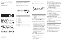
Figure 1
Front panel components
of the z6000 chassis with 2
SL170z servers
Item
Description
1
Handle
2
PCI Slot
3
UID LED/SW
4
Power LED/SW
5
Top: USB 2.0 Port
Bottom: USB 2.0 Port
6
IPMI Port
7
Top: NIC Connector
Bottom: NIC Connector
8
Health LED
9
Serial Port
10
Video Port
Rear Panel Components
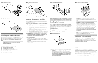
Figure 2
Rear panel components of the z6000 chassis with 2
SL170z servers
Item
Description
1
RJ45 Port
2
Power supply 2
3
Power supply 1
4
UID LED
Server Configuration Resources
In addition to this Installation Sheet, other resources are available for
more information regarding the configuration and maintenance of
your server:
•
For safety information and detailed procedures relating to
installation of options, refer to any installation instructions that
came with the option, as well as the
HP ProLiant SL170z G6
series Server Maintenance and Service Guide
.
•
For safety information and detailed procedures related to the
rest of the steps listed in the “Configuring the Server”section,
refer to relevant chapter of the
HP ProLiant SL1000/6000
Scalable System User Guide
.
•
For information relating to system BIOS configuration and
operating system installation, refer to relevant section of the
HP
ProLiant SL170z G6 Server Software Configuration Guide
.
•
Refer to the
HP ProLiant SL170z G6 Server Easy Set-up CD
for
additional information and updates not provided in this
installation sheet. You can also access additional information
and documentation from the HP website at
, either by connecting directly or through
the Easy Set-up CD.
Server Configuration Overview
The steps listed below give an overview of the necessary setup
procedures for preparing the HP ProLiant SL170z Generation 6
Server for operation:
1.
Connect the AC power cord and peripheral devices.
2.
Power up the server.
3.
Press “F10” to enter BIOS setup.
4.
Note the server BIOS version.
5.
Verify the server BIOS version against the latest BIOS version
listed for this server on the HP website: http://www.hp.com.
6.
If you do not have the latest BIOS, update the BIOS now. Refer
to the
ProLiant SL170z G6 Server Maintenance and Service
Guide
available on the HP website: http://www.hp.com.
7.
Install a supported operating system of your choice. For
detailed procedures, refer to the documentation provided by
the operating system vendor. For a list of operating systems
supported by your ProLiant server, go to
.
Pre- and Post-installation
Procedures
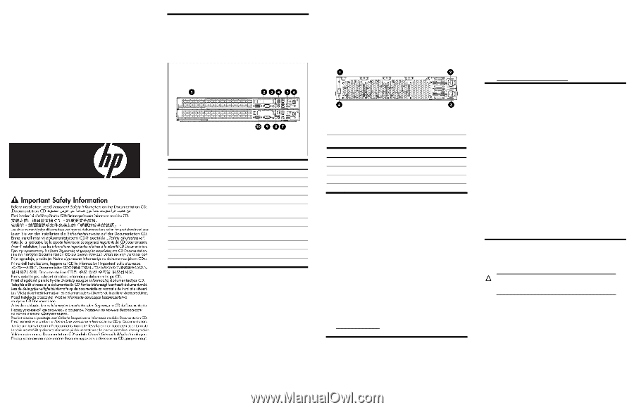
When installing additional options in your HP ProLiant SL170z G6
Server, observe the following procedures:
Pre-installation procedures
1.
Turn off the server and all the peripherals connected to it.
2.
Remove the server from the chassis by following the procedure
described later in the “Removing the server” section.
Post-installation procedures
1.
Be sure all components are installed according to the described
step-by-step instructions.
2.
Check to make sure you have not left loose tools or parts inside
the server.
3.
Reinstall the PCI riser, peripherals, and system cables that you
have removed.
4.
Reinstall the server into the chassis.
5.
Connect all external cables to the system.
6.
Press the power button on the front panel to turn on the server.
Removing the Server
You need to remove the server from the chassis before you can
remove or replace a server component.
CAUTION:
When the servers are operational, tray blank
577723-001 (HP option kit P/N 579069-B21) must be
installed in the server slot after removal of the server.
To remove the server:
1.
Press the tray latch to release the tray handle.
2.
Rotate the tray handle to disengage the power connector.
3.
Pull the server tray assembly out of the chassis.
4.
Install the tray blank in the server slot.
Part number: 539705-002
July 2009 (Second edition)