HP R/T3000 HP UPS R3000 User Guide
HP R/T3000 Manual
 |
View all HP R/T3000 manuals
Add to My Manuals
Save this manual to your list of manuals |
HP R/T3000 manual content summary:
- HP R/T3000 | HP UPS R3000 User Guide - Page 1
HP UPS R3000 User Guide Part Number 192131-007 December 2009 (Seventh Edition) - HP R/T3000 | HP UPS R3000 User Guide - Page 2
Windows Server are U.S. registered trademarks of Microsoft Corporation. Intended audience This guide is for the person who operates, configures, maintains, and troubleshoots UPSs. HP assumes you are qualified in the servicing of high-voltage equipment and trained in recognizing hazards in products - HP R/T3000 | HP UPS R3000 User Guide - Page 3
...24 Starting power to the load...24 Installing the ERM...24 Attaching the ERM front bezel ...25 Switching off the ERM circuit breaker 25 Connecting the ERM to the UPS ...25 Switching on the ERM circuit breaker 26 Charging the ERM batteries...26 UPS operations...27 Modes of operation...27 - HP R/T3000 | HP UPS R3000 User Guide - Page 4
replace batteries 36 Obtaining new batteries ...36 UPS battery replacement procedure 36 Testing the new battery module...38 Replacing the UPS ...38 Replacing the ERM ...38 Updating the UPS firmware ...39 Configuring a USB to serial converter 39 Reassigning the USB COM ports...40 Troubleshooting - HP R/T3000 | HP UPS R3000 User Guide - Page 5
50 UPS spare parts list...50 ERM spare parts list ...51 Hardware options ...51 Technical support...52 Before you contact HP ...52 HP contact information...52 Warranty information...53 Limited warranty ...53 $250,000 Computer Load Protection Guarantee 53 Pre-Failure Battery Warranty...53 Recommended - HP R/T3000 | HP UPS R3000 User Guide - Page 6
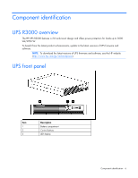
the latest product enhancements, update to the latest versions of UPS firmware and software. NOTE: To download the latest versions of UPS firmware and software, see the HP website (http://www.hp.com/go/rackandpower). UPS front panel Item 1 2 3 Description Battery compartment Control buttons LED - HP R/T3000 | HP UPS R3000 User Guide - Page 7
" on page 24) 2 Standby button Places the UPS in Standby mode (on page 27) 3 Test/Alarm Reset button Silences UPS alarms ("Silencing an audible alarm" on page 31) Initiates a self-test ("Initiating a self-test" on page 30) 4 Configure button Places the UPS in Configure mode (on page 28 - HP R/T3000 | HP UPS R3000 User Guide - Page 8
On 2 General Alarm 3 On Battery 4 Battery Fault 5 Site Wiring Fault 6 Utility 7 Overload 8 76% to 100% load 9 51% to 75% load 10 26% to 50% load 11 0% to 25% load For more information, see "LED and audible alarm troubleshooting (on page 41)" . HP UPS R3000 models UPS model - HP R/T3000 | HP UPS R3000 User Guide - Page 9
International • High-voltage • Detachable country-specific plug UPS R3000 NA and R3000j JPN rear panel Item 1 2 3 4 5 6 7 Description REPO port ERM connector Serial communications port/options slot Load segment 1 (two NEMA 5-15 receptacles) Load segment 2 (two NEMA 5-15 receptacles) Load segment - HP R/T3000 | HP UPS R3000 User Guide - Page 10
bonding screw Power cord with L5-30 plug UPS R3000h NA and R3000h JPN rear panel Item 1 2 3 4 5 6 7 8 9 10 11 Description REPO port ERM connector Serial communications port/options slot Load segment 1 (three IEC-320-C13 receptacles) Load segment 2 (three IEC-320-C13 receptacles) Load segment - HP R/T3000 | HP UPS R3000 User Guide - Page 11
1 2 3 4 5 6 7 8 9 10 11 Description REPO port ERM connector Serial communications port/options slot Load segment 1 (three IEC-320-C13 initiated by power management software. • The REPO feature shuts down UPS units operating under either utility or battery power. Component identification 11 - HP R/T3000 | HP UPS R3000 User Guide - Page 12
battery power when the remote switch was closed, no power is available to the load devices until utility power is restored and the UPS has been manually switch. ERM rear panel Item 1 2 3 Description ERM input connector (from another ERM output) Circuit breaker ERM output connector (to the - HP R/T3000 | HP UPS R3000 User Guide - Page 13
contains important safety instructions that should be followed during installation, operation, and maintenance of the UPS and batteries. WARNING: A risk of personal injury from electric shock and hazardous energy levels exists. The installation of options and routine maintenance and service of this - HP R/T3000 | HP UPS R3000 User Guide - Page 14
equipment nameplate ratings should be used when addressing this concern. • Reliable earthing-Reliable earthing battery recharge date label has passed without the battery being recharged, contact an HP authorized service representative for directions. 2. Transport the packaged unit to its installation - HP R/T3000 | HP UPS R3000 User Guide - Page 15
become unstable if more than one component is extended for any reason. NOTE: If preparing the rails for integrated shipping, follow the same instructions as in "Installing the UPS (on page 18)." NOTE: Mounting hardware for square- and round-holed racks is included in the UPS kit. 1. Loosen the wing - HP R/T3000 | HP UPS R3000 User Guide - Page 16
2. Insert screws through the rack into the mounting rail and the front of each mounting bracket. 3. Install cage nuts or clip nuts into the rear of the rack. Installation 16 - HP R/T3000 | HP UPS R3000 User Guide - Page 17
4. Insert screws through the mounting rail into the cage nuts or clip nuts. 5. Tighten the wing nuts or hex nuts. Installation 17 - HP R/T3000 | HP UPS R3000 User Guide - Page 18
the rear stabilization bracket using hex nuts. Wait until the unit is installed and the brackets are adjusted before tightening the nuts. Installing the UPS Before installing the unit, review and adhere to all warnings provided in "Precautions (on page 13)." WARNING: A risk of personal injury - HP R/T3000 | HP UPS R3000 User Guide - Page 19
communications port CAUTION: Use only the computer interface cable supplied with the UPS to connect the communications port to the host computer. IMPORTANT: Power management software requires the communications port to be appropriately cabled to the host computer. Installation 19 - HP R/T3000 | HP UPS R3000 User Guide - Page 20
to verify polarity while connecting the REPO port. WARNING: To meet the requirements stated in NEC (NFPA 70) Articles 645-10 and 645-11, a UPS installed in a computer equipment room must be connected to a REPO circuit. IMPORTANT: The remote switch must be in the Off (open) position to enable power - HP R/T3000 | HP UPS R3000 User Guide - Page 21
Separate wire pairs are attached to a single, normally-open contact in a parallel connection. HP recommends using different colors for the positive and negative wires. If a connector becomes disconnected and the REPO connection, see "Verifying the REPO port connection (on page 31)" . Installation 21 - HP R/T3000 | HP UPS R3000 User Guide - Page 22
cable NOTE: UPS appearance might vary depending on the specific unit installed. The ground bonding screw is provided as an attachment point for functional grounding or bonding of ungrounded metal parts. The ground bonding cable is not included. Connecting the UPS to utility power Installation 22 - HP R/T3000 | HP UPS R3000 User Guide - Page 23
into a grounded (earthed) electrical outlet that is installed near the equipment and is easily accessible. • enters Standby mode and begins charging the batteries. Connecting devices to the UPS CAUTION: is part of load segment 1 and can be turned off and on using power management software (on - HP R/T3000 | HP UPS R3000 User Guide - Page 24
the UPS into service. IMPORTANT: Charge the batteries for at least 24 hours before supplying backup power to devices. The batteries charge to: • be available the first time the UPS is started. Installing the ERM Before installing the unit, review and adhere to all warnings provided in "Precautions ( - HP R/T3000 | HP UPS R3000 User Guide - Page 25
off the ERM circuit breaker WARNING: To prevent personal injury from electric shock or damage to the equipment, verify that the circuit breaker is in the Off position. Connecting the ERM to the UPS NOTE: Before connecting an ERM to a UPS, remove the label from the ERM connector. Installation 25 - HP R/T3000 | HP UPS R3000 User Guide - Page 26
(2) at the rear of the UPS. NOTE: To install a second ERM, plug the cable from the second ERM into the socket at the rear of the first ERM. Up to two ERM units can be connected. Switching on the ERM circuit breaker Charging the ERM batteries Connect the UPS to a grounded utility power outlet. When - HP R/T3000 | HP UPS R3000 User Guide - Page 27
audible alarm sounds and the Utility LED flashes. Power to the load ceases. IMPORTANT: While in Standby mode, the UPS maintains the charge on the batteries, but no power is available at the output receptacles. The UPS remains in Standby mode until an alternate mode is selected or until utility power - HP R/T3000 | HP UPS R3000 User Guide - Page 28
are illuminated), press the On button to start the UPS on battery power. For the location of buttons, see "UPS front panel ERM configurator tool. To update the UPS firmware or download the ERM configurator tool, see the HP website (http://www.hp.com/go/rackandpower). After the ERMs are installed - HP R/T3000 | HP UPS R3000 User Guide - Page 29
default) UPS is configured for 1 attached ERM UPS is configured for 2 attached ERMs NOTE: For units factory-configured for 200 V or 208 V, the Site Wiring Fault function has been disabled. If reconfiguring a 230 V unit to operate at 208 V, the Site Wiring Fault function must be manually disabled - HP R/T3000 | HP UPS R3000 User Guide - Page 30
indicates the default setting. batteries are less than 90 percent charged. If the UPS detects a problem, the appropriate LED ("UPS front panel LED indicators" on page 8) illuminates and an audible alarm may sound. For information on what to do if the self-test detects a problem, see "Troubleshooting - HP R/T3000 | HP UPS R3000 User Guide - Page 31
is restored. For information about audible alarm conditions, see "LED and audible alarm troubleshooting (on page 41)." Verifying the REPO port connection NOTE: While testing, operate connected equipment in a safe test mode so the effects do not disrupt critical operations. After connecting the REPO - HP R/T3000 | HP UPS R3000 User Guide - Page 32
latest version of HP Power Manager software, see the HP website (http://www.hp.com/go/rackandpower). NOTE: To install and configure the software, see the software user guide. The software user guide is available for download from the HP website (http://www.hp.com/go/rackandpower). HP Power Manager - HP R/T3000 | HP UPS R3000 User Guide - Page 33
Maintenance Removing the UPS front bezel Removing the ERM front bezel Replacing the UPS electronics module This component is hot-swappable and can be replaced without powering down the UPS. Maintenance 33 - HP R/T3000 | HP UPS R3000 User Guide - Page 34
illuminated. 6. Replace the electronics module while holding down the Test/Alarm Reset ERMs. See "Configuring the UPS (on page 28)." 11. Replace the front bezel. Replacing the UPS option card This component is hot-swappable and can be replaced without powering down the UPS. 1. (optional) To replace - HP R/T3000 | HP UPS R3000 User Guide - Page 35
software to be restarted or reconfigured. Replacing the batteries To replace the batteries: 1. Read and observe the requirements in "Important battery safety information (on page 35)" and "Battery care and storage guidelines (on page 36)." 2. Follow the instructions in "UPS battery replacement - HP R/T3000 | HP UPS R3000 User Guide - Page 36
24 hours. d. Update the battery recharge date label. Determining when to replace batteries When the Battery Fault LED illuminates, batteries might need to be replaced within 30 to 60 days. When a battery alarm sounds, initiate a UPS battery self-test to verify that battery replacement is required - HP R/T3000 | HP UPS R3000 User Guide - Page 37
power failure, unless at least one ERM is installed. 2. Remove the UPS front bezel ("Removing the UPS front bezel" on page 33). 3. Disconnect the battery leads. 4. Remove the UPS battery bracket. 5. Remove the UPS battery modules. To replace the components, reverse the removal procedure. IMPORTANT - HP R/T3000 | HP UPS R3000 User Guide - Page 38
. If the installation has not been successful, the Battery Fault LED illuminates. If this occurs, repeat the UPS battery replacement procedure (on page 36), and check the battery terminal connections. If the Battery Fault LED is still illuminated, see "LED and audible alarm troubleshooting (on page - HP R/T3000 | HP UPS R3000 User Guide - Page 39
33) on the ERM that is being replaced. 5. Disconnect the battery leads. 6. Remove the screws securing the ERM to the rack. 7. Remove the ERM from the rack. To replace the component, reverse the removal procedure. Updating the UPS firmware To update the UPS firmware, see the HP website (http://www - HP R/T3000 | HP UPS R3000 User Guide - Page 40
methods. 13. Click OK to close the Advanced screen. 14. Click OK to close the Device Manager screen. 15. Run the firmware Flash batch file program. Follow the instructions provided with the program. Reassigning the USB COM ports To reassign a device from COM 1 to another port: 1. From the open - HP R/T3000 | HP UPS R3000 User Guide - Page 41
page 43) Yes Battery test failure ("Battery condition" on page 43) No Low battery (no utility power) ("UPS is on battery" on page 43) Yes Batteries are disconnected ("Battery condition" on page 43) Yes On battery-No utility power ("UPS is on battery" on page 43) Troubleshooting 41 - HP R/T3000 | HP UPS R3000 User Guide - Page 42
condition, see the HP Power Manager user guide available for download from the HP website (http://www.hp.com/go/rackandpower). 2. Check the batteries: a. Allow the UPS batteries to charge for 24 hours. b. If the Battery Fault LED is red, replace the batteries ("UPS battery replacement procedure" on - HP R/T3000 | HP UPS R3000 User Guide - Page 43
installed, remove and reinsert the module. 2. Allow the UPS batteries to charge for 24 hours. 3. If the LED does not turn off, replace the batteries ("UPS battery replacement procedure" on page 36). 4. If the condition persists, contact an HP authorized service representative. UPS is on battery - HP R/T3000 | HP UPS R3000 User Guide - Page 44
the UPS ("Powering down the UPS" on page 31). 2. If the condition persists, contact an HP authorized service representative. REPO condition Action: • If the remote switch is closed, then open the switch to verify that the load devices are not defective. UPS does not start Action: Troubleshooting 44 - HP R/T3000 | HP UPS R3000 User Guide - Page 45
the UPS ("Configuring the UPS" on page 28). 2. Contact a qualified electrician to verify that the utility power is suitable for the UPS. ERM cannot be configured from the UPS front panel Action: See the HP website (http://www.hp.com/go/rackandpower) to update the UPS firmware. Troubleshooting 45 - HP R/T3000 | HP UPS R3000 User Guide - Page 46
(25 in) 44.1 cm (17.5 in) 37 kg (82 lb) ERM physical specifications Parameter Height Depth Width Weight Value 8.9 cm (3.5 in) 34.3 cm NOTE: An asterisk (*) indicates the default setting. UPS model R3000 NA R3000j JPN R3000h NA R3000h JPN R3000 INTL Utility voltage frequency (Hz) 50/60 - HP R/T3000 | HP UPS R3000 User Guide - Page 47
is 204 for this setting. UPS output specifications UPS model R3000 NA R3000j JPN R3000h NA/JPN R3000 INTL Load segment 1 2 3 1 2 3 1 2 3 1 2 3 Output receptacles 2 x 5-15R UPS model VA R3000 NA R3000j JPN R3000h NA/JPN R3000 INTL 2880 2400 3000 3000 Nominal power rating (W) 2700 2250 2700 - HP R/T3000 | HP UPS R3000 User Guide - Page 48
, valve regulated lead-acid batteries with a 3-5 year service life at 25°C (77°F). The battery modules have a battery string voltage of 120 V. Complete charge takes no more than 24 hours. After approximately 4 hours, the batteries reach 90% charge at default nominal utility voltage and no - HP R/T3000 | HP UPS R3000 User Guide - Page 49
altitude Audible noise Specification 10°C to 40°C (50°F to 104°F); UL-tested at 25°C (77°F) -25°C to 55°C (-13°F to 131 sea level Less than 45 dBA, normal operation Less than 50 dBA, on battery power REPO port specifications The REPO port meets the requirements of NFPA Articles 645-10 - HP R/T3000 | HP UPS R3000 User Guide - Page 50
a spare, visit the HP website (http://www.hp.com/buy/parts). To replace parts under warranty, contact an HP authorized service representative. UPS spare parts list Item 1 * * * * 2 3 * 4 * * * * Description UPS unit NA UPS unit JPN UPS unit HV NA UPS unit HV JPN UPS unit INTL X-slot serial card - HP R/T3000 | HP UPS R3000 User Guide - Page 51
Description Battery modules (2) ERM unit ERM to UPS cable UPS/ERM mounting brackets Mounting rails with screws Spare part number 407407-001 407398-001 407410-001 407408-001 419181-001 * not shown Hardware options For information on the supported hardware options, see the HP website (http://www.hp - HP R/T3000 | HP UPS R3000 User Guide - Page 52
/us/en/wwcontact.html). For HP technical support: • In the United States, for contact options see the Contact HP United States webpage (http://welcome.hp.com/country/us/en/contact_us.html). To contact HP by phone: o Call 1-800-HP-INVENT (1-800-474-6836). This service is available 24 hours a day - HP R/T3000 | HP UPS R3000 User Guide - Page 53
before it actually fails. The Pre-Failure Battery Warranty ensures that the battery is replaced free of charge when a notification that the battery might fail is received from power management software. The battery warranty coverage is 3 years for parts. The warranty for the first year of ownership - HP R/T3000 | HP UPS R3000 User Guide - Page 54
Recommended duration of use Although tests and a multitude of customer experiences have shown no noticeable performance issues with UPSs for significant time periods after expiration of the 3-year limited warranty, we strongly recommend considering replacing UPSs after a maximum of 5 to 6 years of - HP R/T3000 | HP UPS R3000 User Guide - Page 55
may reasonably be expected to be installed in a residential environment (for example, personal computers). The FCC requires devices in both classes to bear a label indicating the interference potential of the device as well as additional operating instructions for the user. FCC rating label The FCC - HP R/T3000 | HP UPS R3000 User Guide - Page 56
installation. If this equipment does cause harmful interference to radio or television reception, which can be determined by turning the equipment off and on, the user States only This device complies with Part 15 of the FCC Rules. Houston, Texas 77269-2000 • 1-800-HP-INVENT (1-800-474-6836). (For - HP R/T3000 | HP UPS R3000 User Guide - Page 57
2004/108/EC Compliance with these directives implies conformity to applicable harmonized European standards (European Norms) which are listed on the EU can be found on the HP website (http://www.hp.com/go/certificates). Disposal of waste equipment by users in private households in the European - HP R/T3000 | HP UPS R3000 User Guide - Page 58
environment. For more information about where you can drop off your waste equipment for recycling, please contact your local city office, your household waste disposal service or the shop where you purchased the product. Japanese notice Regulatory compliance notices 58 - HP R/T3000 | HP UPS R3000 User Guide - Page 59
to recycling or proper disposal, use the public collection system or return them to HP, an authorized HP Partner, or their agents. For more information about battery replacement or proper disposal, contact an authorized reseller or an authorized service provider. Regulatory compliance notices 59 - HP R/T3000 | HP UPS R3000 User Guide - Page 60
or importing firms in accordance with Article 15 of the Waste Disposal Act to indicate the recovery marks on the batteries used in sales, giveaway or promotion. Contact a qualified Taiwanese recycler for proper battery disposal. Power cord statement for Japan Regulatory compliance notices 60 - HP R/T3000 | HP UPS R3000 User Guide - Page 61
floor mats. • Use conductive field service tools. • Use a portable field service kit with a folding static-dissipating work mat. If you do not have any of the suggested equipment for proper grounding, have an authorized reseller install the part. For more information on static electricity - HP R/T3000 | HP UPS R3000 User Guide - Page 62
Acronyms and abbreviations ERM extended runtime module IEC International Electrotechnical Commission LED light-emitting diode NEC National Electrical Code NEMA National Electrical Manufacturers Association NFPA National Fire Protection Association - HP R/T3000 | HP UPS R3000 User Guide - Page 63
troubleshooting 45 ERM, configuring 28 ERM, connecting 25 ERM, identifying components 12 ERM, installing 24 ERM, replacing 38 European Union notice 57 F FCC rating label 55 Federal Communications Commission (FCC) notice 55, 56 firmware, updating 39 frequent switching between battery and - HP R/T3000 | HP UPS R3000 User Guide - Page 64
out of range 43 installation instructions 13, 18, 24 installing the batteries 36 installing the ERM 24 installing the rails 14 installing the UPS 18 internal UPS fault condition 44 International model 11 J Japanese notice 58 K Korean notices 59 L LEDs, testing 30 LEDs, troubleshooting 41 LEDs, unit - HP R/T3000 | HP UPS R3000 User Guide - Page 65
Alarm Reset button, location 7 testing batteries 38 testing LEDs 30 tools 13 troubleshooting 41 U unpacking the components 14 updating the firmware 39 UPS does not start 44 UPS firmware, updating 39 UPS is on battery 43 UPS operations 27 UPS, installing 13, 18 UPS, replacing 38 Utility LED, location
-
 1
1 -
 2
2 -
 3
3 -
 4
4 -
 5
5 -
 6
6 -
 7
7 -
8
-
9
-
10
-
11
-
12
-
13
-
14
-
15
-
16
-
17
-
18
-
19
-
20
-
21
-
22
-
23
-
24
-
25
-
26
-
27
-
28
-
29
-
30
-
31
-
32
-
33
-
34
-
35
-
36
-
37
-
38
-
39
-
40
-
41
-
42
-
43
-
44
-
45
-
46
-
47
-
48
-
49
-
50
-
51
-
52
-
53
-
54
-
55
-
56
-
57
-
58
-
59
-
60
-
61
-
62
-
63
-
64
-
65
 |
 |

HP UPS R3000
User Guide
Part Number 192131-007
December 2009 (Seventh Edition)