HP R/T3000 HP UPS R5000 User Guide
HP R/T3000 Manual
 |
View all HP R/T3000 manuals
Add to My Manuals
Save this manual to your list of manuals |
HP R/T3000 manual content summary:
- HP R/T3000 | HP UPS R5000 User Guide - Page 1
HP UPS R5000 User Guide Abstract This document includes installation, configuration, and operation information for the HP UPS R5000. This document is for the person who installs and maintains power products. HP assumes you are qualified in the servicing of high-voltage equipment and trained in - HP R/T3000 | HP UPS R5000 User Guide - Page 2
to change without notice. The only warranties for HP products and services are set forth in the express warranty statements accompanying such products and services. Nothing herein should be construed as constituting an additional warranty. HP shall not be liable for technical or editorial errors - HP R/T3000 | HP UPS R5000 User Guide - Page 3
clips 25 Charging the UPS batteries ...25 Starting power to the load ...25 Configuring the UPS Network Module...25 Connecting the configuration cable Module settings 28 Installing the ERM ...28 Attaching the ERM front bezel ...29 Connecting the ERM to the UPS ...30 Charging the ERM batteries - HP R/T3000 | HP UPS R5000 User Guide - Page 4
port connection ...33 Powering down the UPS ...34 Power management ...35 Power Protector software ...35 Maintenance ...37 Removing the UPS front bezel ...37 Removing the ERM front bezel...37 Replacing the UPS Network Module ...37 Replacing the batteries ...38 Important battery safety information 38 - HP R/T3000 | HP UPS R5000 User Guide - Page 5
Guarantee 55 Pre-Failure Battery Warranty ...56 Recommended duration of use ...56 Electrostatic discharge ...57 Preventing electrostatic discharge ...57 Grounding methods to prevent electrostatic discharge 57 Support and other resources ...58 Before you contact HP...58 HP contact information ...58 - HP R/T3000 | HP UPS R5000 User Guide - Page 6
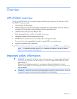
management to increase battery service life, optimize recharge time, and provide a warning before the end of useful battery life • Extended runtime with up to four ERMs per UPS • Easily replaceable battery modules that simplify maintenance • Emergency shutdown control through the REPO port • HP - HP R/T3000 | HP UPS R5000 User Guide - Page 7
Component identification UPS front panel Item 1 2 3 Description LCD display Control buttons Battery compartment Component identification 7 - HP R/T3000 | HP UPS R5000 User Guide - Page 8
UPS front panel controls Item 1 2 3 4 5 Component ESC button Up arrow Down arrow Enter/select button Power on/off button Description Cancel/return to the previous menu Scroll through the menu structure Scroll through the menu structure Select an option • Green-operating • - HP R/T3000 | HP UPS R5000 User Guide - Page 9
communications port HP UPS Network Module Ground bonding screw Input power line cord with NEMA L6-30 plug (NA/JPN) or IEC-309-32A plug (INTL) Load segment 2 circuit breaker Large output NEMA L6-30R receptacle (NA/JPN) or IEC-309-32A receptacle (INTL) associated with load segment 1 ERM connector for - HP R/T3000 | HP UPS R5000 User Guide - Page 10
Item 1 2 3 4 Description ERM input connector for the small plug on the split ERM cable of another ERM output ERM input connector for the large plug on the split ERM cable of another ERM output Split ERM cable with two output connectors that attach to the UPS or another ERM Ground bonding screw - HP R/T3000 | HP UPS R5000 User Guide - Page 11
contains important safety instructions that should be followed during installation, operation, and maintenance of the UPS and batteries. WARNING: A risk of personal injury from electric shock and hazardous energy levels exists. The installation of options and routine maintenance and service of this - HP R/T3000 | HP UPS R5000 User Guide - Page 12
connections to the branch circuit, such as the use of power strips. • Electrical requirements-All models require a dedicated ( battery if the recharge date has passed. If the date on the battery recharge date label has passed without the battery being recharged, contact an HP authorized service - HP R/T3000 | HP UPS R5000 User Guide - Page 13
reason. NOTE: Mounting hardware for square- and round-holed racks is included in the UPS kit. 1. Loosen the wing nuts or hex nuts, and then extend the brackets to the appropriate length. 2. Insert screws through the rack into the mounting rail and the front of each mounting bracket. Installation and - HP R/T3000 | HP UPS R5000 User Guide - Page 14
3. Install clip nuts into the rear of the rack. 4. Insert screws through the mounting rail into the clip nuts. Installation and configuration 14 - HP R/T3000 | HP UPS R5000 User Guide - Page 15
5. Install the rail reinforcement plates and tighten using hex nuts with captive washers included in the kit, instead of the nuts included with the rail. 6. Tighten the wing nuts or hex nuts. Installation and configuration 15 - HP R/T3000 | HP UPS R5000 User Guide - Page 16
installed and the brackets are adjusted before tightening the nuts. Preparing the rails for integrated shipping If the unit is to be shipped in an HP 9000 or 10000 series rack: 1. Remove the hex nuts, flat washers, and lock washers from the mounting rail. 2. Install the rail reinforcement plates and - HP R/T3000 | HP UPS R5000 User Guide - Page 17
that the cleat brackets slide into the channels on the rear stabilization brackets. 5. Attach the chassis to the rack using the supplied screws. Connecting the battery leads WARNING: To prevent personal injury from electric shock or damage to the equipment, remove the - HP R/T3000 | HP UPS R5000 User Guide - Page 18
communications port CAUTION: Use only the computer interface cable supplied with the UPS to connect the communications port to the host computer. IMPORTANT: Power protector software requires the communications port to be appropriately cabled to the host computer. NOTE: This port is only used for - HP R/T3000 | HP UPS R5000 User Guide - Page 19
operating systems using the HP USB to serial converter (part number 304098-001). Depending on your system configuration, a driver System. -orFor Windows Server, click Start, select Control Panel, and then double-click System. 3. Click the Hardware tab. 4. Click Device Manager. The Device Manager - HP R/T3000 | HP UPS R5000 User Guide - Page 20
, reduce the Receive Buffer and Transmit Buffer to the low setting by scrolling down to select low (1). 12. Be sure that the Use FIFO buffers Click OK to close the Device Manager screen. 15. Run the firmware Flash batch file program. Follow the instructions provided with the program. Reassigning - HP R/T3000 | HP UPS R5000 User Guide - Page 21
USB communications port NOTE: This port is only used for firmware upgrades. For additional information, see "Updating the UPS firmware (on page 43)." Connecting the REPO port WARNING: The must be in the Off (open) position to enable power to the output receptacles. Installation and configuration 21 - HP R/T3000 | HP UPS R5000 User Guide - Page 22
, nonshielded wire (AWG #22 - #18, or equivalent). Separate wire pairs are attached to a single, normally-open contact in a parallel connection. HP recommends using different colors for the positive and negative wires. If a connector becomes disconnected and is reconnected with reversed polarity - HP R/T3000 | HP UPS R5000 User Guide - Page 23
a standard Ethernet cable between the network connector on the UPS Network Module and a network jack. This connection is used to access the UPS Network Module remotely through the web interface. The UPS Network Module also uses the network connection to communicate to the configured HPPP Clients - HP R/T3000 | HP UPS R5000 User Guide - Page 24
power outlet. When the UPS is plugged in, it automatically enters Standby mode and begins charging the batteries. high current, large output receptacle. The large output receptacle is part of load segment 1 and can be turned off and on using power management software ("Power Protector software - HP R/T3000 | HP UPS R5000 User Guide - Page 25
placing the UPS in Operate mode. IMPORTANT: AC power must be available the first time the UPS is started. Configuring the UPS Network Module NOTE: For more information about the UPS Network Module, see the HP Infrastructure Management Pack software CD and documentation for complete details. Before - HP R/T3000 | HP UPS R5000 User Guide - Page 26
the steps might be different. 1. Be sure that the UPS is powered on. 2. On the host computer, click Start, and select Programs o Parity-None o Stop bits-1 o Flow control-None Configuring the UPS Network Module network settings On the terminal emulation session screen running on the host computer: 1. - HP R/T3000 | HP UPS R5000 User Guide - Page 27
-screen instructions to highly recommended that browser access to the UPS Network Module is isolated from outside access using a firewall or isolated network. 1. On a network computer, launch a supported Module. The login screen appears. 3. Enter the user name in the User Name field. The default user - HP R/T3000 | HP UPS R5000 User Guide - Page 28
Use the Settings screens of the HP UPS Network Module web interface to configure the UPS Network Module. For more information, see the HP UPS Network Module User Guide on the HP website (http://www.hp.com/support/HPNM_Manuals). Installing the ERM Before installing the ERM, review and observe all - HP R/T3000 | HP UPS R5000 User Guide - Page 29
that the cleat brackets slide into the channels on the rear stabilization brackets. 5. Attach the chassis to the rack using the supplied screws. Attaching the ERM front bezel Installation and configuration 29 - HP R/T3000 | HP UPS R5000 User Guide - Page 30
the UPS to a grounded utility power outlet. When the UPS is plugged in, it automatically enters Standby mode and begins charging the ERM batteries. With the UPS in Standby mode, allow the ERM batteries to charge for at least 24 hours before putting the UPS into service. IMPORTANT: To verify the - HP R/T3000 | HP UPS R5000 User Guide - Page 31
mode: • Power is available at the UPS receptacles. • The UPS charges the batteries as necessary Power button. For the location of buttons, see "UPS front panel controls (on page 8)." Auto-Bypass mode The UPS automatically enters Auto-Bypass mode when one of the following conditions occurs: • Extended - HP R/T3000 | HP UPS R5000 User Guide - Page 32
to the previous menu. Menu map for display functions Main menu UPS Status Submenu - - Alarm status Display information or menu function Load percentage graph, System Status, Estimated Battery Runtime, Battery Charge, Output Voltage and Output Frequency Displays active alarms UPS operations 32 - HP R/T3000 | HP UPS R5000 User Guide - Page 33
Charging/Floating/Resting, Charge Level, ERM Number, and Runtime Displays events and alarms Output watts and VA Output amps and power factor Output voltage and frequency Input voltage and frequency Battery voltage and percent charge Transfers the UPS system to internal Bypass mode When this command - HP R/T3000 | HP UPS R5000 User Guide - Page 34
a REPO. d. Verify that the UPS remains in Operate mode (on page 31). e. If a REPO is initiated, the polarity is reversed. Check and correct the connections. Powering down the UPS 1. Shut down all load devices. 2. Switch the load segment circuit breakers the OFF position. 3. Press and hold the - HP R/T3000 | HP UPS R5000 User Guide - Page 35
). NOTE: To install and configure the software, see the software user guide. The software user guide is available for download from the HP website (http://www.hp.com/go/rackandpower). HP Power Protector: • Does not require complex management systems, which simplifies deployment, configuration, and - HP R/T3000 | HP UPS R5000 User Guide - Page 36
• Delays reboot by load segment after a power outage to sequence the startup of system components. Power management 36 - HP R/T3000 | HP UPS R5000 User Guide - Page 37
Maintenance Removing the UPS front bezel Removing the ERM front bezel Replacing the UPS Network Module This component is hot-swappable and can be replaced without powering down the UPS. Maintenance 37 - HP R/T3000 | HP UPS R5000 User Guide - Page 38
securing the UPS Network Module and slide the module out. To replace the component, reverse the removal procedure. NOTE: Replacing the UPS Network Module might require power management software to be restarted or reconfigured. Replacing the batteries To replace the batteries: 1. Read and observe the - HP R/T3000 | HP UPS R5000 User Guide - Page 39
.47 lb). NOTE: Replace all battery modules at the same time with the same type of batteries originally installed in the UPS. Battery care and storage guidelines • Minimize the amount of time the UPS uses battery power by matching the UPS configuration with the utility voltage. Refer to "Configuring - HP R/T3000 | HP UPS R5000 User Guide - Page 40
2. Disconnect the battery leads. 3. Remove the UPS battery bracket. 4. Remove the UPS battery modules. IMPORTANT: Do not pull the battery leads when removing or installing the batteries. Maintenance 40 - HP R/T3000 | HP UPS R5000 User Guide - Page 41
24 hours before supplying backup power to devices. The batteries charge to: • 80 percent of their capacity within 3 hours • 100 percent of their capacity within 48 hours Replacing the UPS To remove the UPS: 1. Power down all attached load devices. 2. Power down the UPS ("Powering down the UPS" on - HP R/T3000 | HP UPS R5000 User Guide - Page 42
6. Disconnect the battery leads. 7. Remove the UPS battery bracket. Maintenance 42 - HP R/T3000 | HP UPS R5000 User Guide - Page 43
the ERM front bezel" on page 37) on the ERM that is being replaced. 3. Remove the screws securing the ERM to the rack. 4. Remove the ERM from the rack. To replace the component, reverse the removal procedure. Updating the UPS firmware To update the UPS firmware, see the HP website (http://www.hp.com - HP R/T3000 | HP UPS R5000 User Guide - Page 44
do not mean that the output power is affected. Instead, they are preventive alarms intended to alert you of a possible condition. The following table describes typical alarms and conditions. If an alarm appears with a service code, contact HP technical support ("Support and other resources" on page - HP R/T3000 | HP UPS R5000 User Guide - Page 45
On Manual Bypass 149 Service Battery 159 Output Overload Level 2 162 Output Overload Level 3 168 UPS On Battery 169 UPS On Bypass 170 UPS Off 172 UPS On Command 173 UPS Off Command 174 Battery Shutdown 181 UPS Control Power ON 191 Battery Test Failed 194 Site Wiring Problem - HP R/T3000 | HP UPS R5000 User Guide - Page 46
alarm condition, see the HP Power Manager user guide available for download from the HP website (http://www.hp.com/go/rackandpower). 2. Check the batteries: a. Allow the UPS batteries to charge for 48 hours. b. If a Battery Fault occurs, replace the batteries. 3. Reduce the load: Troubleshooting 46 - HP R/T3000 | HP UPS R5000 User Guide - Page 47
is in a low battery condition. Action: 1. Verify that the power management software is not delaying the shutdown of attached servers when the UPS is in a low battery condition. 2. Allow the UPS batteries to charge for 48 hours. 3. If a Battery Fault occurs, replace the batteries. Troubleshooting 47 - HP R/T3000 | HP UPS R5000 User Guide - Page 48
, contact an HP authorized service representative. UPS does not start Action: 1. Be sure that the power cord is plugged in to a utility power receptacle. 2. Check the power source at the utility power receptacle. UPS frequently switches between utility and battery power Action: Troubleshooting 48 - HP R/T3000 | HP UPS R5000 User Guide - Page 49
is in Auto-Bypass mode Action: 1. If power management software is being used, check the log files to obtain specific error information to help identify the problem. For more information about the causes of a general fault condition, see the HP Power Manager user guide available for download from the - HP R/T3000 | HP UPS R5000 User Guide - Page 50
indicates the default setting. UPS model R5000 NA/JPN R5000 INTL Utility voltage frequency (Hz) 50/60 50/60 Available settings utility voltage (VAC) Dedicated branch circuit rating (A) 200/208*/220/230/ 30 240 200/208/220/230*/ 32 240 Line cord Nondetachable power cord with NEMA L6-30 plug - HP R/T3000 | HP UPS R5000 User Guide - Page 51
for each C13 receptacle on the extension bar is 10 A. The total maximum current for the extension bar is 12 A. Power protection specifications UPS model R5000 NA/JPN R5000 INTL VA 5000 5000 Nominal power rating (W) 4500 4500 Nominal voltage setting 200/208, 220, 230, 240 200/208, 220, 230, 240 - HP R/T3000 | HP UPS R5000 User Guide - Page 52
44 123 50 16 44 80 7 25 100 5.7 20 * NA/JPN model only Runtime with four ERMs (minutes)* 436 145 83 64 Minimum battery runtime Minimum battery runtimes are at beginning of life. Load % Internal battery Runtime with runtime one ERM (minutes) (minutes) 20 36 100 50 12 36 80 - HP R/T3000 | HP UPS R5000 User Guide - Page 53
2,000 m (6,600 ft) above sea level 15,000 m (49,212 ft) above sea level Less than 45 dBA, normal operation Less than 50 dBA, on battery power REPO port specifications The REPO port meets the requirements of NFPA Articles 645-10 and 645-11 for a Disconnecting Means. Specifications 53 - HP R/T3000 | HP UPS R5000 User Guide - Page 54
the HP website (http://www.hp.com/buy/parts). To replace parts under warranty, contact an HP authorized service representative. UPS spare parts list Item Description 1 UPS unit NA/JPN 2 UPS unit INTL 3 UPS Network Module 4 UPS battery module 5 ERM unit 6 UPS/ERM mounting hardware - HP R/T3000 | HP UPS R5000 User Guide - Page 55
, and regulatory information, see Safety and Compliance Information for Server, Storage, Power, Networking, and Rack Products, available at the HP website (http://www.hp.com/support/Safety-Compliance-EnterpriseProducts). Turkey RoHS material content declaration Ukraine RoHS material content - HP R/T3000 | HP UPS R5000 User Guide - Page 56
, extends the advantage of a 3-year limited warranty by applying it to the battery before it actually fails. The Pre-Failure Battery Warranty ensures that the battery is replaced free of charge when a notification that the battery might fail is received from power protector software. The battery - HP R/T3000 | HP UPS R5000 User Guide - Page 57
when setting up the system or handling parts. A discharge of static electricity from a finger or other conductor may damage system boards or other static- or dissipating floor mats. • Use conductive field service tools. • Use a portable field service kit with a folding static-dissipating work mat. - HP R/T3000 | HP UPS R5000 User Guide - Page 58
System log for 3 days before the failure was detected. For more information, see the HP iLO 4 User Guide or HP Intelligent Provisioning User Guide on the HP website (http://www.hp (service upgrade), see the Support & Drivers website (http://www8.hp.com/us/en/support-drivers.html). If the problem - HP R/T3000 | HP UPS R5000 User Guide - Page 59
Acronyms and abbreviations ERM extended runtime module IEC International Electrotechnical Commission PDU power distribution unit PFC power factor corrected REPO remote emergency power off RMS root-mean-square UPS uninterruptible power system Acronyms and abbreviations 59 - HP R/T3000 | HP UPS R5000 User Guide - Page 60
documentation that meets your needs. To help us improve the documentation, send any errors, suggestions, or comments to Documentation Feedback (mailto:[email protected]). Include the document title and part number, version number, or the URL when submitting your feedback. Documentation feedback 60 - HP R/T3000 | HP UPS R5000 User Guide - Page 61
output receptacle, connecting 24 high-current output receptacle, location 8 HP technical support 58 I input voltage is out of range 47 installing the ERM 28 insufficient backup time 48 internal UPS fault condition 47 J Japanese notice 55 L LCD panel 7 LEDs, troubleshooting 44 limited warranty 55 - HP R/T3000 | HP UPS R5000 User Guide - Page 62
tools 11 troubleshooting 44 U unpacking the components 12 updating the firmware 43 UPS does not start 48 UPS firmware, updating 43 UPS is on battery 49 UPS Network Module 6, 25, 28 UPS operations 31 UPS, replacing 41 utility power condition 49 utility power, connecting 24 V voltage specifications 51
-
 1
1 -
 2
2 -
 3
3 -
 4
4 -
 5
5 -
 6
6 -
 7
7 -
8
-
9
-
10
-
11
-
12
-
13
-
14
-
15
-
16
-
17
-
18
-
19
-
20
-
21
-
22
-
23
-
24
-
25
-
26
-
27
-
28
-
29
-
30
-
31
-
32
-
33
-
34
-
35
-
36
-
37
-
38
-
39
-
40
-
41
-
42
-
43
-
44
-
45
-
46
-
47
-
48
-
49
-
50
-
51
-
52
-
53
-
54
-
55
-
56
-
57
-
58
-
59
-
60
-
61
-
62
 |
 |

HP UPS R5000
User Guide
Abstract
This document includes installation, configuration, and operation information for the HP UPS R5000. This document is for the person who installs and
maintains power products. HP assumes you are qualified in the servicing of high-voltage equipment and trained in recognizing hazards in products
with hazardous energy levels.
Part Number: 637909-003
February 2013
Edition: 3