HP Special Edition L2005CL HP Special Edition L2000 Notebook PC and Compaq Pre
HP Special Edition L2005CL Manual
 |
View all HP Special Edition L2005CL manuals
Add to My Manuals
Save this manual to your list of manuals |
HP Special Edition L2005CL manual content summary:
- HP Special Edition L2005CL | HP Special Edition L2000 Notebook PC and Compaq Pre - Page 1
AMD processors. July 2005 This guide is a troubleshooting reference used for maintaining and servicing the notebook. It provides comprehensive information on identifying notebook features, components, and spare parts; troubleshooting notebook problems; and performing notebook disassembly procedures - HP Special Edition L2005CL | HP Special Edition L2000 Notebook PC and Compaq Pre - Page 2
be construed as constituting an additional warranty. HP shall not be liable for technical or editorial errors or omissions contained herein. Maintenance and Service Guide HP Special Edition L2000 Notebook PC Compaq Presario V2000 Notebook PC First Edition: July 2005 Document Part Number: 393671-001 - HP Special Edition L2005CL | HP Special Edition L2000 Notebook PC and Compaq Pre - Page 3
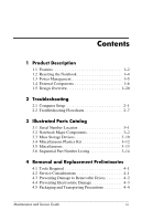
Components 1-6 1.5 Design Overview 1-20 2 Troubleshooting 2.1 Computer Setup 2-1 2.2 Troubleshooting Flowcharts 2-7 3 Illustrated Parts Catalog 3.1 Serial Removal and Replacement Preliminaries 4.1 Tools Required 4-1 4.2 Service Considerations 4-1 4.3 Preventing Damage to Removable Drives 4-2 - HP Special Edition L2005CL | HP Special Edition L2000 Notebook PC and Compaq Pre - Page 4
5.18 Processor 5-40 5.19 System Board 5-42 5.20 LED Board 5-47 6 Specifications A Connector Pin Assignments B Power Cord Set Requirements C Screw Listing Index iv Maintenance and Service Guide - HP Special Edition L2005CL | HP Special Edition L2000 Notebook PC and Compaq Pre - Page 5
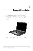
Notebook PC and the Compaq Presario V2000 Notebook PC offer advanced modularity, AMD Turion™ 64 Mobile Technology and Mobile AMD Sempron™ processors, and extensive multimedia support. HP Special Edition L2000 and Compaq Presario V2000 Maintenance and Service Guide 1-1 - HP Special Edition L2005CL | HP Special Edition L2000 Notebook PC and Compaq Pre - Page 6
Maintenance and Service Guide to "full-featured" and "defeatured" units. A notebook model is considered to be full-featured if it has 3 Universal Serial Bus ports and the following components: ■ 6-in-1 digital card reader ■ Expansion port 2 ■ Bluetooth wireless communications support ■ IEEE 1394 - HP Special Edition L2005CL | HP Special Edition L2000 Notebook PC and Compaq Pre - Page 7
cord ■ 6-cell or 12-cell Li-Ion battery pack ■ Stereo speakers with volume up and down buttons ■ Support for the following optical drives: ❏ 8X Max DVD-ROM drive ❏ 24X DVD/CD-RW Combo Drive ❏ 8X (select models only) ❏ RJ-45 (network) ❏ RJ-11 (modem) ❏ PC Card Maintenance and Service Guide 1-3 - HP Special Edition L2005CL | HP Special Edition L2000 Notebook PC and Compaq Pre - Page 8
Product Description 1.2 Resetting the Notebook If the notebook you are servicing has an unknown password, follow these steps to clear the password. These steps also clear CMOS: 1. . 6. Turn on the notebook. All passwords and all CMOS settings have been cleared. 1-4 Maintenance and Service Guide - HP Special Edition L2005CL | HP Special Edition L2000 Notebook PC and Compaq Pre - Page 9
management features that extend battery operating time and conserve power. The notebook supports the following power management features: ■ Standby ■ Hibernation ■ Setting customization standby button ■ Advanced Configuration and Power Management (ACPM) compliance Maintenance and Service Guide 1-5 - HP Special Edition L2005CL | HP Special Edition L2000 Notebook PC and Compaq Pre - Page 10
Product Description 1.4 External Components The external components on the front of the notebook are shown below and described in Table 1-1. Front Components 1-6 Maintenance and Service Guide - HP Special Edition L2005CL | HP Special Edition L2000 Notebook PC and Compaq Pre - Page 11
) jack Connect optional headphones or powered stereo speakers. Also connect the audio function of an audio/video device such as a television or VCR. Maintenance and Service Guide 1-7 - HP Special Edition L2005CL | HP Special Edition L2000 Notebook PC and Compaq Pre - Page 12
Product Description The external components on the right side of the notebook are shown below and described in Table 1-2. Right-Side Components 1-8 Maintenance and Service Guide - HP Special Edition L2005CL | HP Special Edition L2000 Notebook PC and Compaq Pre - Page 13
(2) Connect an optional USB device. 6-in-1 Memory Reader In Windows, supports digital memory cards. (select models only) 1394 port (select models only only) On: A digital memory card is being accessed. Optical drive Supports an optical disc. S-Video-out jack (select models only) Connects an - HP Special Edition L2005CL | HP Special Edition L2000 Notebook PC and Compaq Pre - Page 14
as a printer, or a soft surface, such as pillows, thick rugs or clothing, to block airflow. Power connector Connects an AC adapter cable. 1-10 Maintenance and Service Guide - HP Special Edition L2005CL | HP Special Edition L2000 Notebook PC and Compaq Pre - Page 15
an optional network cable. RJ-11 (modem) jack Connects the modem cable. USB connector (select Connects an optional USB device. models only) PC Card slot Supports an optional Type I or Type II 32-bit (CardBus) or 16-bit PC Card. PC Card eject button Ejects an optional PC Card from the - HP Special Edition L2005CL | HP Special Edition L2000 Notebook PC and Compaq Pre - Page 16
Product Description The notebook keyboard components are shown below and described in Table 1-5. Keyboard Components 1-12 Maintenance and Service Guide - HP Special Edition L2005CL | HP Special Edition L2000 Notebook PC and Compaq Pre - Page 17
an external numeric keypad. num lock key Enables numeric lock, turns on the embedded numeric keypad, and turns on the num lock light. Maintenance and Service Guide 1-13 - HP Special Edition L2005CL | HP Special Edition L2000 Notebook PC and Compaq Pre - Page 18
Display switch Table 1-6 Top Components Function On: Caps lock is on. If the notebook is closed while on, turns off the display. 1-14 Maintenance and Service Guide - HP Special Edition L2005CL | HP Special Edition L2000 Notebook PC and Compaq Pre - Page 19
button Mutes or restores volume. Mute light On: Volume is muted. Num lock light On: Num lock or the internal keypad is on. Maintenance and Service Guide 1-15 - HP Special Edition L2005CL | HP Special Edition L2000 Notebook PC and Compaq Pre - Page 20
Product Description The notebook TouchPad components are shown below and described in Table 1-7. TouchPad Components 1-16 Maintenance and Service Guide - HP Special Edition L2005CL | HP Special Edition L2000 Notebook PC and Compaq Pre - Page 21
and right buttons on an external mouse. TouchPad vertical scrolling region Scrolls upward or downward. TouchPad on/off button Enables/disables the TouchPad. Maintenance and Service Guide 1-17 - HP Special Edition L2005CL | HP Special Edition L2000 Notebook PC and Compaq Pre - Page 22
Components Item 1 2 3 Table 1-8 Bottom Components Component Function Battery pack Holds a battery pack. Battery pack release latch Releases a battery pack from the battery bay. Optical drive Supports an optical disc. 1-18 Maintenance and Service Guide - HP Special Edition L2005CL | HP Special Edition L2000 Notebook PC and Compaq Pre - Page 23
notebook functionality. Then contact Customer Care. Hard drive bay Holds the internal hard drive. Memory module compartment Contains 2 memory slots that support replaceable memory modules. The number of preinstalled memory modules varies by notebook model. Maintenance and Service Guide 1-19 - HP Special Edition L2005CL | HP Special Edition L2000 Notebook PC and Compaq Pre - Page 24
, battery fast charging, and software applications. Exhaust air is displaced through the ventilation grill located on the left side of the notebook. 1-20 Maintenance and Service Guide - HP Special Edition L2005CL | HP Special Edition L2000 Notebook PC and Compaq Pre - Page 25
trained by HP should repair this equipment. All troubleshooting and repair procedures are detailed to allow only subassembly restarts the operating system after you exit Computer Setup. ✎ Pointing devices are not supported in Computer Setup; you must use the keyboard to navigate and make selections. - HP Special Edition L2005CL | HP Special Edition L2000 Notebook PC and Compaq Pre - Page 26
Troubleshooting keys to select the Advanced menu, select Language Support, and then press F5 or F6 until the Exit > Exit Discarding Changes, and then follow the instructions on the screen. ❏ To exit and save all Changes, and then follow the instructions on the screen. Your preferences are set - HP Special Edition L2005CL | HP Special Edition L2000 Notebook PC and Compaq Pre - Page 27
Troubleshooting language, use the arrow keys to select the Advanced menu, select Language Support, and then press F5 or F6 until the appropriate language is highlighted. Select Exit > Exit Saving Changes, and then follow the instructions on the screen. When the computer restarts, the factory settings - HP Special Edition L2005CL | HP Special Edition L2000 Notebook PC and Compaq Pre - Page 28
Troubleshooting Selecting from the Main Menu Select System Information Table 2-1 Main Menu To Do This ■ View identification information about the turning on (not restarting) the notebook. Enable diskette drive or optical drive for inclusion in MultiBoot. 2-4 Maintenance and Service Guide - HP Special Edition L2005CL | HP Special Edition L2000 Notebook PC and Compaq Pre - Page 29
Troubleshooting Selecting from the Advanced Menu Select Video Graphic Mode Dedicated Video Memory Total Video Memory Language Support Boot Order Accessibility Options Embedded WLAN device Embedded Bluetooth device self-test on any hard drive in the system. Maintenance and Service Guide 2-5 - HP Special Edition L2005CL | HP Special Edition L2000 Notebook PC and Compaq Pre - Page 30
Troubleshooting Select Exit Saving Changes Exit Discarding Changes Load Setup Defaults Table 2-5 Exit Menu To Do This Save the notebook. Replace configuration settings in Computer Setup with factory default settings. (Identification information is retained.) 2-6 Maintenance and Service Guide - HP Special Edition L2005CL | HP Special Edition L2000 Notebook PC and Compaq Pre - Page 31
Flowcharts Overview Flowchart Description 2.1 "Flowchart 2.1-Initial Troubleshooting" 2.2 "Flowchart 2.2-No Power, Part 1" 2.3 "Flowchart 2.3-No Power, Part 2" 2.4 "Flowchart 2.4-No Power, Part Part 3" 2.13 "Flowchart 2.13-No OS Loading, Diskette Drive" Maintenance and Service Guide 2-7 - HP Special Edition L2005CL | HP Special Edition L2000 Notebook PC and Compaq Pre - Page 32
Troubleshooting Table 2-6 Troubleshooting Flowcharts Overview (Continued) Flowchart Description 2.14 "Flowchart 2.14-No OS Loading, Optical Drive" 2.15 " 19 "Flowchart 2.19-Nonfunctioning Pointing Device" 2.20 "Flowchart 2.20-No Network/Modem Connection" 2-8 Maintenance and Service Guide - HP Special Edition L2005CL | HP Special Edition L2000 Notebook PC and Compaq Pre - Page 33
Flowchart 2.1-Initial Troubleshooting Begin troubleshooting. N Is there power? Y Go to "Flowchart 2.2-No Power, Part 1." N Beeps, LEDs, or error messages? Y N Is there 2.19-Nonfunctioning Pointing Device." Go to "Flowchart 2.20-No Network/Modem Connection." Maintenance and Service Guide 2-9 - HP Special Edition L2005CL | HP Special Edition L2000 Notebook PC and Compaq Pre - Page 34
Troubleshooting Flowchart 2.2-No Power, Part 1 No power (power LED is off). Remove from docking device (if applicable). N Power up on battery power? Y the lid switch or the main power switch. Go to "Flowchart 2.8-Nonfunctioning Docking Device (if applicable)." 2-10 Maintenance and Service Guide - HP Special Edition L2005CL | HP Special Edition L2000 Notebook PC and Compaq Pre - Page 35
Troubleshooting Flowchart 2.3-No Power, Part 2 Continued from "Flowchart 2.2-No Power, Part 1." Visually check for debris in battery socket and on? Y Replace power supply (if applicable). N Done Power on? Y Go to "Flowchart 2.4-No Power, Part 3." Done Maintenance and Service Guide 2-11 - HP Special Edition L2005CL | HP Special Edition L2000 Notebook PC and Compaq Pre - Page 36
Troubleshooting Flowchart 2.4-No Power, Part 3 Continued from "Flowchart 2.3-No Power, Part 2." Plug directly into AC outlet. Y Power LED on? N adapter? Internal Go to "Flowchart 2.5-No Power, Part 4." Replace external AC adapter. N Power on? Y Done Done 2-12 Maintenance and Service Guide - HP Special Edition L2005CL | HP Special Edition L2000 Notebook PC and Compaq Pre - Page 37
Flowchart 2.5-No Power, Part 4 Continued from "Flowchart 2.4-No Power, Part 3." Troubleshooting Open notebook. Y Loose or damaged parts? N Reseat loose components and boards and * *NOTE: Replace these items as a set to prevent shorting out among components. Maintenance and Service Guide 2-13 - HP Special Edition L2005CL | HP Special Edition L2000 Notebook PC and Compaq Pre - Page 38
Troubleshooting Flowchart 2.6-No Video, Part 1 No video. Docking Device Stand-alone or docking device? Go to "Flowchart 2.7-No Video, Part System board N Video OK? Y Try another display. N Internal and external video OK? Y Replace system board. Done Done 2-14 Maintenance and Service Guide - HP Special Edition L2005CL | HP Special Edition L2000 Notebook PC and Compaq Pre - Page 39
Troubleshooting Flowchart 2.7-No Video, Part 2 Continued from "Flowchart 2.6-No Video, Part 1." Remove notebook from docking device, if Done video OK? N Adjust external monitor display. Go to "Flowchart 2.8-Nonfunctioning Docking Device (if applicable)." Maintenance and Service Guide 2-15 - HP Special Edition L2005CL | HP Special Edition L2000 Notebook PC and Compaq Pre - Page 40
Troubleshooting Flowchart 2.8-Nonfunctioning Docking Device (if applicable) Nonfunctioning docking device. Reseat power cord in docking device operating? N Done Test replacement docking device with new notebook. Remove notebook, replace docking device. 2-16 Maintenance and Service Guide - HP Special Edition L2005CL | HP Special Edition L2000 Notebook PC and Compaq Pre - Page 41
, go to "Flowchart 2.14-No OS Loading, Optical Drive." No OS loading from network, go to "Flowchart 2.20-No Network/Modem Connection." *NOTE: Before beginning troubleshooting, always check cable connections, cable ends, and drives for bent or damaged pins. Maintenance and Service Guide 2-17 - HP Special Edition L2005CL | HP Special Edition L2000 Notebook PC and Compaq Pre - Page 42
Troubleshooting Flowchart 2.10-No OS Loading, Hard Drive, Part 1 OS not loading from hard drive. Y Nonsystem disk message? N Reseat external hard drive. drive? Y Go to "Flowchart 2.13-No OS Loading, Diskette Drive." Go to "Flowchart 2.17-Nonfunctioning Device." 2-18 Maintenance and Service Guide - HP Special Edition L2005CL | HP Special Edition L2000 Notebook PC and Compaq Pre - Page 43
Troubleshooting Flowchart 2.11-No OS Loading, Hard Drive, Part 2 Continued from "Flowchart 2.10-No OS Loading, Hard Drive, Part 1." Reseat booted? N Go to "Flowchart 2.12-No OS Loading, Hard Drive, Part 3." Load OS using Operating System disc (if applicable). Maintenance and Service Guide 2-19 - HP Special Edition L2005CL | HP Special Edition L2000 Notebook PC and Compaq Pre - Page 44
Troubleshooting Flowchart 2.12-No OS Loading, Hard Drive, Part 3 Continued from "Flowchart 2.11-No OS Loading, Hard Drive, Part 2." N System files Replace hard drive. Replace hard drive. N Fix bad sectors. Boot from hard drive? Replace hard drive. Y Done 2-20 Maintenance and Service Guide - HP Special Edition L2005CL | HP Special Edition L2000 Notebook PC and Compaq Pre - Page 45
Troubleshooting Flowchart 2.13-No OS Loading, Diskette Drive OS not loading from diskette drive. ? Done Section 1.2, "Resetting the N Notebook," for instructions. Change boot priority using the Setup utility. Go to "Flowchart 2.17-Nonfunctioning Device." Maintenance and Service Guide 2-21 - HP Special Edition L2005CL | HP Special Edition L2000 Notebook PC and Compaq Pre - Page 46
Troubleshooting Flowchart 2.14-No OS Loading, Optical Drive No OS loading from CD-ROM or DVD- the notebook. Booting order correct? N Refer to Section 1.2, "Resetting the Notebook," for instructions. Go to "Flowchart 2.17-Nonfunctioning Device." Correct boot order using the Setup utility. 2-22 - HP Special Edition L2005CL | HP Special Edition L2000 Notebook PC and Compaq Pre - Page 47
Troubleshooting Flowchart 2.15-No Audio, Part 1 No audio. Y Turn up audio internally or Audio? Done externally. N Y Notebook in docking 2." Dock notebook in replacement docking device. Go to "Flowchart 2.17-Nonfunctioning Device." N Y Audio? Done Maintenance and Service Guide 2-23 - HP Special Edition L2005CL | HP Special Edition L2000 Notebook PC and Compaq Pre - Page 48
Troubleshooting Flowchart 2.16-No Audio, Part 2 Continued from "Flowchart 2.15-No Audio, Part 1." N Audio driver in OS configured? Y components individually, retesting after each replacement: ■ Internal speakers. ■ Audio board (if applicable). ■ System board. 2-24 Maintenance and Service Guide - HP Special Edition L2005CL | HP Special Edition L2000 Notebook PC and Compaq Pre - Page 49
Troubleshooting Flowchart 2.17-Nonfunctioning Device Nonfunctioning device. Reseat device. Unplug the nonfunctioning device from the notebook and to "Flowchart 2.9-No Operating System (OS) Loading." N Device boots properly? Y Done Replace diskette drive. Done Maintenance and Service Guide 2-25 - HP Special Edition L2005CL | HP Special Edition L2000 Notebook PC and Compaq Pre - Page 50
Troubleshooting Flowchart 2.18-Nonfunctioning Keyboard Keyboard not operating properly. Connect notebook to good external keyboard. N External device Y Replace internal keyboard or cable. Y Keyboard Done operating Done properly? N Replace system board. 2-26 Maintenance and Service Guide - HP Special Edition L2005CL | HP Special Edition L2000 Notebook PC and Compaq Pre - Page 51
Troubleshooting Flowchart 2.19-Nonfunctioning Pointing Device Pointing device not operating properly. Connect notebook to good external pointing internal pointing device or cable. Y Done Pointing device operating Done properly? N Replace system board. Maintenance and Service Guide 2-27 - HP Special Edition L2005CL | HP Special Edition L2000 Notebook PC and Compaq Pre - Page 52
Troubleshooting Flowchart 2.20-No Network/Modem Connection No network or modem connection. N Network or modem jack active? Y Replace jack or ). Replace NIC/modem (if applicable). Y Network or modem connection Done working? N Replace system board. 2-28 Maintenance and Service Guide - HP Special Edition L2005CL | HP Special Edition L2000 Notebook PC and Compaq Pre - Page 53
ordering parts or requesting information, provide the notebook serial number and model number located on the bottom of the notebook. Serial Number Location Maintenance and Service Guide 3-1 - HP Special Edition L2005CL | HP Special Edition L2000 Notebook PC and Compaq Pre - Page 54
Illustrated Parts Catalog 3.2 Notebook Major Components Notebook Major Components 3-2 Maintenance and Service Guide - HP Special Edition L2005CL | HP Special Edition L2000 Notebook PC and Compaq Pre - Page 55
394363-121 For use on Compaq Presario V2000 models in the United States 394363-001 LED board (includes cable, not illustrated) 394374-001 Maintenance and Service Guide 3-3 - HP Special Edition L2005CL | HP Special Edition L2000 Notebook PC and Compaq Pre - Page 56
Illustrated Parts Catalog Notebook Major Components 3-4 Maintenance and Service Guide - HP Special Edition L2005CL | HP Special Edition L2000 Notebook PC and Compaq Pre - Page 57
-001 394259-001 397346-001 394258-001 394257-001 397345-001 394256-001 394255-001 394253-001 394252-001 394303-001 395373-001 Maintenance and Service Guide 3-5 - HP Special Edition L2005CL | HP Special Edition L2000 Notebook PC and Compaq Pre - Page 58
Illustrated Parts Catalog Notebook Major Components 3-6 Maintenance and Service Guide - HP Special Edition L2005CL | HP Special Edition L2000 Notebook PC and Compaq Pre - Page 59
-001 394367-001 394275-001 391883-001 395728-001 395729-001 395730-001 395731-001 394359-001 394360-001 394362-001 394361-001 Maintenance and Service Guide 3-7 - HP Special Edition L2005CL | HP Special Edition L2000 Notebook PC and Compaq Pre - Page 60
Illustrated Parts Catalog Notebook Major Components 3-8 Maintenance and Service Guide - HP Special Edition L2005CL | HP Special Edition L2000 Notebook PC and Compaq Pre - Page 61
drive cover (includes 2 captive screws) Memory module compartment cover (includes 2 captive screws) Mini PCI compartment cover (includes 1 captive screw) Notebook feet (not illustrated) Maintenance and Service Guide 3-9 - HP Special Edition L2005CL | HP Special Edition L2000 Notebook PC and Compaq Pre - Page 62
-GB 80-GB 60-GB 40-GB Spare Part Number 394358-001 394357-001 394355-001 394354-001 394353-001 394356-001 3-10 Maintenance and Service Guide - HP Special Edition L2005CL | HP Special Edition L2000 Notebook PC and Compaq Pre - Page 63
(not illustrated) Spare Part Number 395728-001 395729-001 395730-001 395731-001 394359-001 394360-001 394362-001 394361-001 364727-001 Maintenance and Service Guide 3-11 - HP Special Edition L2005CL | HP Special Edition L2000 Notebook PC and Compaq Pre - Page 64
Kit Spare Part Number 394368-001 Item 1 2 3 4 Description Includes: Mini PCI compartment cover Memory module compartment cover Notebook feet (4) Hard drive cover 3-12 Maintenance and Service Guide - HP Special Edition L2005CL | HP Special Edition L2000 Notebook PC and Compaq Pre - Page 65
PM2.0×6.0 screw ■ Phillips PM2.0×8.0 screw ■ Phillips PM2.0×5.0 screw ■ Phillips PM2.0×4.0 screw ■ Phillips PM1.5×3.5 screw ■ Phillips PM2.0×9.0 captive spring-loaded, shoulder screw (includes C-clips) Maintenance and Service Guide 3-13 - HP Special Edition L2005CL | HP Special Edition L2000 Notebook PC and Compaq Pre - Page 66
thermal pad) AMD Turion 64 ML-28 (1.6-GHz) processor (includes thermal pad) AMD Turion 64 ML-30 (1.6-GHz) processor (includes thermal pad) 3-14 Maintenance and Service Guide - HP Special Edition L2005CL | HP Special Edition L2000 Notebook PC and Compaq Pre - Page 67
frame and connector) 5400-rpm, 60-GB hard drive (includes frame and connector) 5400-rpm, 80-GB hard drive (includes frame and connector) Maintenance and Service Guide 3-15 - HP Special Edition L2005CL | HP Special Edition L2000 Notebook PC and Compaq Pre - Page 68
cover for use on Compaq Presario V2000 models without wireless capability (includes wireless button and light) Speaker assembly LED board (includes cable) 3-16 Maintenance and Service Guide - HP Special Edition L2005CL | HP Special Edition L2000 Notebook PC and Compaq Pre - Page 69
Special Edition L2000 models 8X DVD±RW/R and CD-RW Dual Layer Combo Drive, LightScribe, for use on HP Special Edition L2000 models Maintenance and Service Guide 3-17 - HP Special Edition L2005CL | HP Special Edition L2000 Notebook PC and Compaq Pre - Page 70
397346-001 Description Mobile AMD Sempron 3300+ (2.0-GHz) processor (includes thermal pad) AMD Turion 64 ML-32 (1.8-GHz) processor (includes thermal pad) 3-18 Maintenance and Service Guide - HP Special Edition L2005CL | HP Special Edition L2000 Notebook PC and Compaq Pre - Page 71
■ Tool kit-includes connector removal tool, loopback plugs, and case utility tool 4.2 Service Considerations The following sections include some of the considerations that you should keep in mind all accompanying screws) away from the work area to prevent damage. Maintenance and Service Guide 4-1 - HP Special Edition L2005CL | HP Special Edition L2000 Notebook PC and Compaq Pre - Page 72
parts. Apply pressure only at the points designated in the maintenance instructions. Cables and Connectors Ä CAUTION: When servicing the notebook, ensure that cables are placed in their proper locations the drive and ensure that the optical drive tray is closed. 4-2 Maintenance and Service Guide - HP Special Edition L2005CL | HP Special Edition L2000 Notebook PC and Compaq Pre - Page 73
work perfectly throughout a normal cycle. Or the device might function normally for a while, then degrade in the internal layers, reducing its life expectancy. Maintenance and Service Guide 4-3 - HP Special Edition L2005CL | HP Special Edition L2000 Notebook PC and Compaq Pre - Page 74
ground and that proper materials are selected to avoid static charging. When grounding is not possible, use an ionizer to dissipate electric charges. 4-4 Maintenance and Service Guide - HP Special Edition L2005CL | HP Special Edition L2000 Notebook PC and Compaq Pre - Page 75
properly grounded work surface and use properly grounded tools and equipment. ■ Use conductive field service tools, such as cutters, screwdrivers, and vacuums. ■ When using fixtures that must input signals before inserting or removing connectors or test equipment. Maintenance and Service Guide 4-5 - HP Special Edition L2005CL | HP Special Edition L2000 Notebook PC and Compaq Pre - Page 76
of one megohm resistance between the operator and ground. To be effective, the conductive strips must be worn in contact with the skin. 4-6 Maintenance and Service Guide - HP Special Edition L2005CL | HP Special Edition L2000 Notebook PC and Compaq Pre - Page 77
with ground cords of one megohm resistance ■ Static-dissipative tables or floor mats with hard ties to the ground ■ Field service kits ■ Static awareness labels ■ Material-handling packages ■ Nonconductive plastic bags, tubes, or boxes ■ Metal tote boxes ■ Electrostatic voltage levels and - HP Special Edition L2005CL | HP Special Edition L2000 Notebook PC and Compaq Pre - Page 78
4-2 Static-Shielding Materials Material Use Voltage Protection Level Antistatic plastic Bags 1,500 V Carbon-loaded plastic Floor mats 7,500 V Metallized laminate Floor mats 5,000 V 4-8 Maintenance and Service Guide - HP Special Edition L2005CL | HP Special Edition L2000 Notebook PC and Compaq Pre - Page 79
procedures. There are as many as 54 screws, in 8 different sizes and types, that may need to be removed, replaced, or loosened when servicing the notebook. Make special note of each screw size and location during removal and replacement. Refer to Appendix C, "Screw Listing," for detailed information - HP Special Edition L2005CL | HP Special Edition L2000 Notebook PC and Compaq Pre - Page 80
Removal and Replacement Procedures 5.1 Serial Number Report the notebook serial number to HP when requesting information or ordering spare parts. The serial number is located on the bottom of the notebook. Serial Number Location 5-2 Maintenance and Service Guide - HP Special Edition L2005CL | HP Special Edition L2000 Notebook PC and Compaq Pre - Page 81
install a device and then receive a warning message, remove the device to restore notebook functionality. Then contact Customer Care. Optical Drive 1 Switch Cover 2 Keyboard 4 Maintenance and Service Guide 5-3 - HP Special Edition L2005CL | HP Special Edition L2000 Notebook PC and Compaq Pre - Page 82
connected to the notebook. 3. Disconnect the power cord. Battery Pack Spare Part Number Information 12-cell, 8.8-AHr 6-cell, 4.4-AHr 394275-001 391883-001 5-4 Maintenance and Service Guide - HP Special Edition L2005CL | HP Special Edition L2000 Notebook PC and Compaq Pre - Page 83
battery pack 2 and swing it back. d. Remove the battery pack. Removing the Battery Pack Reverse the above procedure to install the battery pack. Maintenance and Service Guide 5-5 - HP Special Edition L2005CL | HP Special Edition L2000 Notebook PC and Compaq Pre - Page 84
-GB 394358-001 394357-001 4200-rpm 100-GB 80-GB 60-GB 40-GB 394355-001 394354-001 394353-001 394356-001 5-6 Maintenance and Service Guide - HP Special Edition L2005CL | HP Special Edition L2000 Notebook PC and Compaq Pre - Page 85
drive cover. ✎ The hard drive cover is included in the Miscellaneous Plastics Kit, spare part number 394368-001. Removing the Hard Drive Cover Maintenance and Service Guide 5-7 - HP Special Edition L2005CL | HP Special Edition L2000 Notebook PC and Compaq Pre - Page 86
Removal and Replacement Procedures 5. Grasp the mylar tab 1 on the hard drive and lift the hard drive until it disconnects from the notebook. 6. Slide the hard drive 2 to the left and remove it from the hard drive bay. Removing the Hard Drive 5-8 Maintenance and Service Guide - HP Special Edition L2005CL | HP Special Edition L2000 Notebook PC and Compaq Pre - Page 87
connector 3 off the hard drive. Removing the Hard Drive Frame and Connector Reverse the above procedure to install and reassemble the hard drive. Maintenance and Service Guide 5-9 - HP Special Edition L2005CL | HP Special Edition L2000 Notebook PC and Compaq Pre - Page 88
the Miscellaneous Plastics Kit, spare part 394368-001. The feet attach to the base enclosure as illustrated below. Replacing the Notebook Feet 5-10 Maintenance and Service Guide - HP Special Edition L2005CL | HP Special Edition L2000 Notebook PC and Compaq Pre - Page 89
394352-001 394351-001 394350-001 1. Prepare the notebook for disassembly (refer to Section 5.3). 2. Position the notebook with the rear panel toward you. Maintenance and Service Guide 5-11 - HP Special Edition L2005CL | HP Special Edition L2000 Notebook PC and Compaq Pre - Page 90
memory module compartment cover is included in the Miscellaneous Plastics Kit, spare part number 394368-001. Removing the Memory Module Compartment Cover 5-12 Maintenance and Service Guide - HP Special Edition L2005CL | HP Special Edition L2000 Notebook PC and Compaq Pre - Page 91
with a notch 3 to prevent incorrect installation into the memory module socket. Removing the Memory Module Reverse the above procedure to install a memory module. Maintenance and Service Guide 5-13 - HP Special Edition L2005CL | HP Special Edition L2000 Notebook PC and Compaq Pre - Page 92
Removal and Replacement Procedures 5.7 Mini PCI Communications Module Mini PCI Communications Module Spare Part Number Information Mini PCI 802.11b/g WLAN communications module 394462-001 1. Prepare the notebook for disassembly (Section 5.3). 5-14 Maintenance and Service Guide - HP Special Edition L2005CL | HP Special Edition L2000 Notebook PC and Compaq Pre - Page 93
. ✎ The Mini PCI compartment cover is included in the Miscellaneous Plastics Kit, spare part number 394368-001. Removing the Mini PCI Compartment Cover Maintenance and Service Guide 5-15 - HP Special Edition L2005CL | HP Special Edition L2000 Notebook PC and Compaq Pre - Page 94
incorrect installation into the Mini PCI socket. Removing a Mini PCI Communications Module Reverse the above procedure to install a Mini PCI communications module. 5-16 Maintenance and Service Guide - HP Special Edition L2005CL | HP Special Edition L2000 Notebook PC and Compaq Pre - Page 95
, LightScribe 395728-001 395729-001 395730-001 395731-001 394359-001 394360-001 394362-001 394361-001 1. Prepare the notebook for disassembly (Section 5.3). Maintenance and Service Guide 5-17 - HP Special Edition L2005CL | HP Special Edition L2000 Notebook PC and Compaq Pre - Page 96
optical drive 3 to the left. 5. Remove the optical drive. Removing the Optical Drive Reverse the above procedure to install an optical drive. 5-18 Maintenance and Service Guide - HP Special Edition L2005CL | HP Special Edition L2000 Notebook PC and Compaq Pre - Page 97
the notebook for disassembly (Section 5.3). 2. Remove the two PM2.0×5.0 screws that secure the switch cover to the notebook. Removing the Switch Cover Screws Maintenance and Service Guide 5-19 - HP Special Edition L2005CL | HP Special Edition L2000 Notebook PC and Compaq Pre - Page 98
it disengages from the notebook. 6. Remove the switch cover. Removing the Switch Cover Reverse the above procedure to install the switch cover. 5-20 Maintenance and Service Guide - HP Special Edition L2005CL | HP Special Edition L2000 Notebook PC and Compaq Pre - Page 99
for disassembly (Section 5.3). 2. Remove the switch cover (Section 5.9). 3. Remove the four PM2.0×4.0 screws that secure the keyboard to the notebook. Releasing the Keyboard Maintenance and Service Guide 5-21 - HP Special Edition L2005CL | HP Special Edition L2000 Notebook PC and Compaq Pre - Page 100
Removal and Replacement Procedures 4. Swing the rear edge of the keyboard up and forward until it rests on the palm rest. Releasing the Keyboard 5-22 Maintenance and Service Guide - HP Special Edition L2005CL | HP Special Edition L2000 Notebook PC and Compaq Pre - Page 101
disconnect the keyboard cable 2 from the system board. Disconnecting the Keyboard Cable 6. Remove the keyboard. Reverse the above procedure to install the keyboard. Maintenance and Service Guide 5-23 - HP Special Edition L2005CL | HP Special Edition L2000 Notebook PC and Compaq Pre - Page 102
394349-001 394348-001 1. Prepare the notebook for disassembly (Section 5.3). 2. Remove the memory module compartment (Section 5.6) and Mini PCI compartment covers (Section 5.7). 5-24 Maintenance and Service Guide - HP Special Edition L2005CL | HP Special Edition L2000 Notebook PC and Compaq Pre - Page 103
5.9). 5. Remove the keyboard (Section 5.10). 6. Turn the notebook display-side up with the front toward you. 7. Open the display as far as possible. Maintenance and Service Guide 5-25 - HP Special Edition L2005CL | HP Special Edition L2000 Notebook PC and Compaq Pre - Page 104
cover. 10. Remove the cables from the clips 3 in the top cover. Disconnecting the Display Cable and Removing the Wireless Antenna Cables 5-26 Maintenance and Service Guide - HP Special Edition L2005CL | HP Special Edition L2000 Notebook PC and Compaq Pre - Page 105
the display assembly when removing the following screws. Failure to support the display assembly can result in damage to the display assembly and other notebook components. Removing the Display Assembly Reverse the above procedure to install the display assembly Maintenance and Service Guide 5-27 - HP Special Edition L2005CL | HP Special Edition L2000 Notebook PC and Compaq Pre - Page 106
assembly (Section 5.11) 2. Remove the fifteen PM2.0×8.0 screws that secure the base enclosure to the notebook. Removing the Base Enclosure Screws, Part 1 5-28 Maintenance and Service Guide - HP Special Edition L2005CL | HP Special Edition L2000 Notebook PC and Compaq Pre - Page 107
Removal and Replacement Procedures 3. Remove the three PM2.0×5.0 screws that secure the base enclosure to the notebook. Removing the Base Enclosure Screws, Part 2 Maintenance and Service Guide 5-29 - HP Special Edition L2005CL | HP Special Edition L2000 Notebook PC and Compaq Pre - Page 108
Removal and Replacement Procedures 4. Lift the base enclosure straight up and remove it. Removing the Base Enclosure Reverse the above procedure to install the base enclosure. 5-30 Maintenance and Service Guide - HP Special Edition L2005CL | HP Special Edition L2000 Notebook PC and Compaq Pre - Page 109
board and replace it on the replacement USB/S-Video controller board. See Section 5.14, "Bluetooth Module," for Bluetooth module replacement instructions. 1. Prepare the notebook for disassembly (Section 5.3) and remove the following components: ❏ Hard drive (Section 5.4) ❏ Switch cover (Section - HP Special Edition L2005CL | HP Special Edition L2000 Notebook PC and Compaq Pre - Page 110
the USB/S-Video controller board. Removing the USB/S-Video Controller Board Reverse the above procedure to install the USB/S-Video controller board. 5-32 Maintenance and Service Guide - HP Special Edition L2005CL | HP Special Edition L2000 Notebook PC and Compaq Pre - Page 111
: ❏ Hard drive (Section 5.4) ❏ Switch cover (Section 5.9) ❏ Keyboard (Section 5.10) ❏ Display assembly (Section 5.11) ❏ Base enclosure (Section 5.12) ❏ USB/S-Video controller board (Section 5.13) Maintenance and Service Guide 5-33 - HP Special Edition L2005CL | HP Special Edition L2000 Notebook PC and Compaq Pre - Page 112
the USB/S-Video controller board. 5. Remove the Bluetooth module 3. Removing the Bluetooth Module Reverse the above procedure to install the Bluetooth module. 5-34 Maintenance and Service Guide - HP Special Edition L2005CL | HP Special Edition L2000 Notebook PC and Compaq Pre - Page 113
(Section 5.3) and remove the following components: ❏ Hard drive (Section 5.4) ❏ Switch cover (Section 5.9) ❏ Keyboard (Section 5.10) ❏ Display assembly (Section 5.11) ❏ Base enclosure (Section 5.12) Maintenance and Service Guide 5-35 - HP Special Edition L2005CL | HP Special Edition L2000 Notebook PC and Compaq Pre - Page 114
5.3) and remove the following components: ❏ Hard drive (Section 5.4) ❏ Switch cover (Section 5.9) ❏ Keyboard (Section 5.10) ❏ Display assembly (Section 5.11) ❏ Base enclosure (Section 5.12) 5-36 Maintenance and Service Guide - HP Special Edition L2005CL | HP Special Edition L2000 Notebook PC and Compaq Pre - Page 115
Removal and Replacement Procedures 2. Remove the RTC battery from the socket on the system board. Removing the RTC Battery Reverse the above procedure to install the RTC battery. Make sure the battery is installed with the "+" side facing up. Maintenance and Service Guide 5-37 - HP Special Edition L2005CL | HP Special Edition L2000 Notebook PC and Compaq Pre - Page 116
5.3) and remove the following components: ❏ Hard drive (Section 5.4) ❏ Switch cover (Section 5.9) ❏ Keyboard (Section 5.10) ❏ Display assembly (Section 5.11) ❏ Base enclosure (Section 5.12) 5-38 Maintenance and Service Guide - HP Special Edition L2005CL | HP Special Edition L2000 Notebook PC and Compaq Pre - Page 117
fan assembly to the system board. 5. Remove the fan assembly 4. Removing the Fan Assembly Reverse the above procedure to install the fan assembly. Maintenance and Service Guide 5-39 - HP Special Edition L2005CL | HP Special Edition L2000 Notebook PC and Compaq Pre - Page 118
components: ❏ Hard drive (Section 5.4) ❏ Switch cover (Section 5.9) ❏ Keyboard (Section 5.10) ❏ Display assembly (Section 5.11) ❏ Base enclosure (Section 5.12) ❏ Fan assembly (Section 5.17) 5-40 Maintenance and Service Guide - HP Special Edition L2005CL | HP Special Edition L2000 Notebook PC and Compaq Pre - Page 119
should be aligned in the left-rear corner when you install the processor. Removing the Processor Reverse the above procedure to install a processor. Maintenance and Service Guide 5-41 - HP Special Edition L2005CL | HP Special Edition L2000 Notebook PC and Compaq Pre - Page 120
replacement system board: ■ Memory modules (Section 5.6) ■ Mini PCI communications module (Section 5.7) ■ RTC battery (Section 5.16) ■ Fan assembly (Section 5.17) ■ Processor (Section 5.18) 5-42 Maintenance and Service Guide - HP Special Edition L2005CL | HP Special Edition L2000 Notebook PC and Compaq Pre - Page 121
. 3. Release the ZIF connector 1 to which the TouchPad cable is connected and disconnect the cable 2 from the system board. Disconnecting the TouchPad Cable Maintenance and Service Guide 5-43 - HP Special Edition L2005CL | HP Special Edition L2000 Notebook PC and Compaq Pre - Page 122
PM2.0×5.0 screws 3 that secure the system board to the top cover. Disconnecting the LED Board Cable and Removing the System Board Screws 5-44 Maintenance and Service Guide - HP Special Edition L2005CL | HP Special Edition L2000 Notebook PC and Compaq Pre - Page 123
the top cover 1 forward. 11. Lift the front of the system board 2 until the audio connectors 3 are clear. Releasing the System Board, Part 2 Maintenance and Service Guide 5-45 - HP Special Edition L2005CL | HP Special Edition L2000 Notebook PC and Compaq Pre - Page 124
Removal and Replacement Procedures 12. Release the front edge of the top cover. 13. Slide the system board to the left at an angle and remove it from the top cover. Removing the System Board Reverse the above procedure to install the system board. 5-46 Maintenance and Service Guide - HP Special Edition L2005CL | HP Special Edition L2000 Notebook PC and Compaq Pre - Page 125
/S-Video controller board (Section 5.13) ❏ Speaker assembly (Section 5.15) ❏ System board (Section 5.19) 2. Turn the notebook upside down with the front toward you. Maintenance and Service Guide 5-47 - HP Special Edition L2005CL | HP Special Edition L2000 Notebook PC and Compaq Pre - Page 126
to the top cover. 5. Remove the LED board 4. Removing the LED Board Screws Reverse the above procedure to install the LED board. 5-48 Maintenance and Service Guide - HP Special Edition L2005CL | HP Special Edition L2000 Notebook PC and Compaq Pre - Page 127
.6°F) maximum wet bulb temperature ✎ Applicable product safety standards specify thermal limits for plastic surfaces. The notebook operates well within this range of temperatures. Maintenance and Service Guide 6-1 - HP Special Edition L2005CL | HP Special Edition L2000 Notebook PC and Compaq Pre - Page 128
, 0.5 oct/min sweep rate ✎ Applicable product safety standards specify thermal limits for plastic surfaces. The notebook operates well within this range of temperatures. 6-2 Maintenance and Service Guide - HP Special Edition L2005CL | HP Special Edition L2000 Notebook PC and Compaq Pre - Page 129
11.0 in 8.2 in 14.0 in 0.279 × 0.279 mm 1280 × 768 RGB vertical stripe Edge lit 80 × 25 4 W +/-40° horizontal, +20/-40° vertical typical Maintenance and Service Guide 6-3 - HP Special Edition L2005CL | HP Special Edition L2000 Notebook PC and Compaq Pre - Page 130
Care for details. *1 GB = 1 billion bytes when referring to hard drive storage capacity. Accessible capacity is less. †Actual drive specifications may differ slightly. 6-4 Maintenance and Service Guide - HP Special Edition L2005CL | HP Special Edition L2000 Notebook PC and Compaq Pre - Page 131
kg 11.1 V 4.4 Ah 48 Wh 5°C to 45°C 0°C to 60°C 0.79 in 3.70 in 5.28 in 0.75 lb 41°F to 113°F 32°F to 140°F Maintenance and Service Guide 6-5 - HP Special Edition L2005CL | HP Special Edition L2000 Notebook PC and Compaq Pre - Page 132
-RW Photo CD (single and multisession) CD-Bridge Write: CD-R and CD-RW 1.5 cm (0.59 in) 12 cm (4.72 in) 8 cm (3.15 in) 6-6 Maintenance and Service Guide - HP Special Edition L2005CL | HP Special Edition L2000 Notebook PC and Compaq Pre - Page 133
KB/s at 1X CD rate) 10,800 KB/s (1352 KB/s at 1X DVD rate) 16.6 MB/s Startup time < 15 seconds Stop time < 6 seconds Maintenance and Service Guide 6-7 - HP Special Edition L2005CL | HP Special Edition L2000 Notebook PC and Compaq Pre - Page 134
and multisession) CD-Bridge Write: CD-R and CD-RW DVD-R and DVD-RW 1.5 cm (0.59 in) 12 cm (4.72 in) 8 cm (3.15 in) 6-8 Maintenance and Service Guide - HP Special Edition L2005CL | HP Special Edition L2000 Notebook PC and Compaq Pre - Page 135
/s (1,352 KB/s at 1X DVD rate) 2,700 KB/s (1,352 KB/s at 1X DVD rate) 16.6 MB/s Startup time < 15 seconds Stop time < 6 seconds Maintenance and Service Guide 6-9 - HP Special Edition L2005CL | HP Special Edition L2000 Notebook PC and Compaq Pre - Page 136
-R CD-RW Photo CD (single and multisession) CD-Bridge 1.5 cm (0.59 in) 12 cm (4.72 in) 8 cm (3.15 in) 1.2 mm (0.047 in) 6-10 Maintenance and Service Guide - HP Special Edition L2005CL | HP Special Edition L2000 Notebook PC and Compaq Pre - Page 137
KB/s at 1X CD rate) 10,800 KB/s (1352 KB/s at 1X DVD rate) 16.6 MB/s Startup time < 10 seconds Stop time < 3 seconds Maintenance and Service Guide 6-11 - HP Special Edition L2005CL | HP Special Edition L2000 Notebook PC and Compaq Pre - Page 138
Specifications Hardware DMA DMA0 DMA1 DMA2 DMA3 DMA4 DMA5 DMA6 DMA7 Table 6-8 System DMA System Function Not applicable Not applicable Not applicable Not applicable Direct memory access controller Available for PC Card Not assigned Not assigned 6-12 Maintenance and Service Guide - HP Special Edition L2005CL | HP Special Edition L2000 Notebook PC and Compaq Pre - Page 139
/Wireless 2200BG TI OHCI 1394 host controller TI PCI1410 CardBus controller *Default configuration ✎ PC Card may assert IRQ3, IRQ4, IRQ5, IRQ7, or IRQ20. Maintenance and Service Guide 6-13 - HP Special Edition L2005CL | HP Special Edition L2000 Notebook PC and Compaq Pre - Page 140
fast Ethernet Controller IRQ23 SDA Standard Compliant SD Host Controller *Default configuration ✎ PC Card may assert IRQ3, IRQ4, IRQ5, IRQ7, or IRQ20. 6-14 Maintenance and Service Guide - HP Special Edition L2005CL | HP Special Edition L2000 Notebook PC and Compaq Pre - Page 141
Direct memory access controller System board resources Programmable interrupt controller System board resources Direct memory access controller Numeric data processor Secondary IDE Channel Maintenance and Service Guide 6-15 - HP Special Edition L2005CL | HP Special Edition L2000 Notebook PC and Compaq Pre - Page 142
System board resources System board resources ISAPNP Read Data Port System board resources System board resources System board resources System board resources 6-16 Maintenance and Service Guide - HP Special Edition L2005CL | HP Special Edition L2000 Notebook PC and Compaq Pre - Page 143
/810x Family Fast Ethernet NIC PCI standard PCI-to-PCI bridge Texas Instruments PCIxx21/x515 Cardbus Controller Texas Instruments PCIxx21/x515 Cardbus Controller Maintenance and Service Guide 6-17 - HP Special Edition L2005CL | HP Special Edition L2000 Notebook PC and Compaq Pre - Page 144
OpenHCD USB Host Controller Standard Enhanced PCI to USB Host Controller ATI SMBus System board System board System board resources System board 6-18 Maintenance and Service Guide - HP Special Edition L2005CL | HP Special Edition L2000 Notebook PC and Compaq Pre - Page 145
Instruments PCIxx21 Integrated FlashMedia Controller SDA Standard Compliant SD Host Controller SDA Standard Compliant SD Host Controller SDA Standard Compliant SD Host Controller Maintenance and Service Guide 6-19 - HP Special Edition L2005CL | HP Special Edition L2000 Notebook PC and Compaq Pre - Page 146
-PCI bridge ATI MOBILITY RADEON Xpress 200 Series PCI bus PCI bus Texas Instruments PCIxx21/x515 Cardbus Controller System board PCI bus 6-20 Maintenance and Service Guide - HP Special Edition L2005CL | HP Special Edition L2000 Notebook PC and Compaq Pre - Page 147
A Connector Pin Assignments Table A-1 Audio-In (Microphone) Pin Signal 1 Audio signal in 2 Audio signal in Pin Signal 3 Ground Maintenance and Service Guide A-1 - HP Special Edition L2005CL | HP Special Edition L2000 Notebook PC and Compaq Pre - Page 148
Connector Pin Assignments Table A-2 Audio-Out (Headphone) Pin Signal 1 Audio out, left channel 2 Audio out, right channel Pin Signal 3 Ground Table A-3 Universal Serial Bus Pin Signal 1 +5 VDC 2 Data - Pin Signal 3 Data + 4 Ground A-2 Maintenance and Service Guide - HP Special Edition L2005CL | HP Special Edition L2000 Notebook PC and Compaq Pre - Page 149
Connector Pin Assignments Table A-4 S-Video-Out Pin Signal 1 TV-Ground 2 TV-CVBS 3 TV-Ground 4 TV-Ground Pin Signal 5 TV-CD 6 TV-Ground 7 TV-YD Maintenance and Service Guide A-3 - HP Special Edition L2005CL | HP Special Edition L2000 Notebook PC and Compaq Pre - Page 150
analog Pin Signal 9 +5 VDC 10 Ground 11 Monitor detect 12 DDC 2B data 13 Horizontal sync 14 Vertical sync 15 DDC 2B clock A-4 Maintenance and Service Guide - HP Special Edition L2005CL | HP Special Edition L2000 Notebook PC and Compaq Pre - Page 151
Connector Pin Assignments Table A-6 RJ-45 (Network) Pin Signal 1 Transmit + 2 Transmit - 3 Receive + 4 Unused Pin Signal 5 Unused 6 Receive - 7 Unused 8 Unused Maintenance and Service Guide A-5 - HP Special Edition L2005CL | HP Special Edition L2000 Notebook PC and Compaq Pre - Page 152
Connector Pin Assignments Table A-7 RJ-11 (Modem) Pin Signal 1 Unused 2 Tip 3 Ring Pin Signal 4 Unused 5 Unused 6 Unused A-6 Maintenance and Service Guide - HP Special Edition L2005CL | HP Special Edition L2000 Notebook PC and Compaq Pre - Page 153
equipment is purchased. Power cord sets for use in other countries must meet the requirements of the country where the notebook is used. Maintenance and Service Guide B-1 - HP Special Edition L2005CL | HP Special Edition L2000 Notebook PC and Compaq Pre - Page 154
of an EN 60 320/IEC 320 Standard Sheet C13 connector for mating with the appliance inlet on the back of the notebook. B-2 Maintenance and Service Guide - HP Special Edition L2005CL | HP Special Edition L2000 Notebook PC and Compaq Pre - Page 155
or VCTF, 3-conductor, 1.00 mm² conductor size. The wall plug must be a two-pole grounding type with a Japanese Industrial Standard C8303 (7 A, 125 V) configuration. Maintenance and Service Guide B-3 - HP Special Edition L2005CL | HP Special Edition L2000 Notebook PC and Compaq Pre - Page 156
coupler and wall plug) must bear the certification mark of the agency responsible for evaluation in the country where it will be used. B-4 Maintenance and Service Guide - HP Special Edition L2005CL | HP Special Edition L2000 Notebook PC and Compaq Pre - Page 157
4 4.0 mm 3.0 mm 5.0 mm Where used: 4 screws that secure the hard drive frame to the hard drive (documented in Section 5.4) Phillips PM3.0×4.0 Screw Locations Maintenance and Service Guide C-1 - HP Special Edition L2005CL | HP Special Edition L2000 Notebook PC and Compaq Pre - Page 158
Mini PCI compartment cover to the notebook (screw is captured on the cover by C clips; documented in Section 5.7) Phillips PM2.0×6.0 Captive Screw Locations C-2 Maintenance and Service Guide - HP Special Edition L2005CL | HP Special Edition L2000 Notebook PC and Compaq Pre - Page 159
Screw Listing Table C-3 Phillips PM2.0×6.0 Screw Head mm Color Qty. Length Thread Width Black 4 6.0 mm 2.0 mm 4.0 mm Where used: 4 screws that secure the display assembly to the notebook (documented in Section 5.11) Phillips PM2.0×6.0 Screw Locations Maintenance and Service Guide C-3 - HP Special Edition L2005CL | HP Special Edition L2000 Notebook PC and Compaq Pre - Page 160
Screw Listing Table C-4 Phillips PM2.0×8.0 Screw Head mm Color Qty. Length Thread Width Black 16 8.0 mm 2.0 mm 4.5 mm Where used: One screw that secures the optical drive to the notebook (documented in Section 5.8) Phillips PM2.0×8.0 Screw Location C-4 Maintenance and Service Guide - HP Special Edition L2005CL | HP Special Edition L2000 Notebook PC and Compaq Pre - Page 161
8.0 mm 2.0 mm 4.5 mm Where used: 15 screws that secure the base enclosure to the notebook (documented in Section 5.12) Phillips PM2.0×8.0 Screw Locations Maintenance and Service Guide C-5 - HP Special Edition L2005CL | HP Special Edition L2000 Notebook PC and Compaq Pre - Page 162
Screw Listing Table C-5 Phillips PM2.0×5.0 Screw Head mm Color Qty. Length Thread Width Silver 14 5.0 mm 2.0 mm 4.5 mm Where used: 2 screws that secure the switch cover to notebook (documented in Section 5.9) Phillips PM2.0×5.0 Screw Locations C-6 Maintenance and Service Guide - HP Special Edition L2005CL | HP Special Edition L2000 Notebook PC and Compaq Pre - Page 163
Silver 14 5.0 mm 2.0 mm 4.5 mm Where used: 3 screws that secure the base enclosure to notebook (documented in Section 5.12) Phillips PM2.0×5.0 Screw Locations Maintenance and Service Guide C-7 - HP Special Edition L2005CL | HP Special Edition L2000 Notebook PC and Compaq Pre - Page 164
2.0 mm 4.5 mm Where used: 2 screws that secure the USB/S-Video controller board to the notebook (documented in Section 5.13) Phillips PM2.0×5.0 Screw Locations C-8 Maintenance and Service Guide - HP Special Edition L2005CL | HP Special Edition L2000 Notebook PC and Compaq Pre - Page 165
5.0 mm 2.0 mm 4.5 mm Where used: One screw that secures the fan assembly to the notebook (documented in Section 5.17) Phillips PM2.0×5.0 Screw Location Maintenance and Service Guide C-9 - HP Special Edition L2005CL | HP Special Edition L2000 Notebook PC and Compaq Pre - Page 166
14 5.0 mm 2.0 mm 4.5 mm Where used: 4 screws that secure the system board to notebook (documented in Section 5.19) Phillips PM2.0×5.0 Screw Locations C-10 Maintenance and Service Guide - HP Special Edition L2005CL | HP Special Edition L2000 Notebook PC and Compaq Pre - Page 167
14 5.0 mm 2.0 mm 4.5 mm Where used: 2 screws that secure the LED board to the notebook (documented in Section 5.20) Phillips PM2.0×5.0 Screw Locations Maintenance and Service Guide C-11 - HP Special Edition L2005CL | HP Special Edition L2000 Notebook PC and Compaq Pre - Page 168
Screw Listing Table C-6 Phillips PM2.0×4.0 Screw mm Color Qty. Length Thread Black 4 4.0 mm 2.0 mm Where used: 4 screws that secure the keyboard to the notebook (documented in Section 5.10) Head Width 4.5 mm Phillips PM2.0×4.0 Screw Locations C-12 Maintenance and Service Guide - HP Special Edition L2005CL | HP Special Edition L2000 Notebook PC and Compaq Pre - Page 169
3.0 mm Where used: 2 screws that secure the Bluetooth module to the USB/S-Video controller board (documented in Section 5.14) Phillips PM1.5×3.5 Screw Locations Maintenance and Service Guide C-13 - HP Special Edition L2005CL | HP Special Edition L2000 Notebook PC and Compaq Pre - Page 170
used: 4 screws that secure the fan assembly to the notebook (documented in Section 5.17) Phillips PM1.5×9.0 Captive Spring-Loaded Shoulder Screw Locations C-14 Maintenance and Service Guide - HP Special Edition L2005CL | HP Special Edition L2000 Notebook PC and Compaq Pre - Page 171
media cable, spare part number 3-13, 3-14 arrow keys 1-13 audio troubleshooting 2-23 audio-in (microphone) jack location 1-7 pin assignments A-1 audio-out part number 3-7, 3-14, 5-33 bottom components 1-18 C cables, service considerations 4-2 caps lock key 1-13 caps lock light 1-14 components bottom - HP Special Edition L2005CL | HP Special Edition L2000 Notebook PC and Compaq Pre - Page 172
, service considerations 4-2 D design overview 1-20 disassembly sequence chart 5-3 diskette drive, OS loading problems 2-21 display assembly removal 5-24 spare part numbers 3-3, 3-15, 3-17, 5-24 specifications 6-3 display release button 1-7 display switch 1-14 docking device, troubleshooting - HP Special Edition L2005CL | HP Special Edition L2000 Notebook PC and Compaq Pre - Page 173
10 flowcharts, troubleshooting no audio grounding equipment and methods 4-6 H hard drive OS loading problems 2-18 precautions 4-2 removal 5-6 spare part numbers 3-9, removal 5-21 spare part numbers 3-3, 3-16, 3-17, 5-21 troubleshooting 2-26 keyboard components 1-12 keypad keys 1-13 L label area 1- - HP Special Edition L2005CL | HP Special Edition L2000 Notebook PC and Compaq Pre - Page 174
1-11 pin assignments A-6 modem, troubleshooting 2-28 monitor port location 1-11 problems 2-22 precautions 4-2 removal 5-17 spare part numbers 3-7, 3-11 specifications 6-6, 6-8, 6-10 P packing precautions 4-4 PC Card eject button 1-11 PC Card slot 1-11 Index-4 Maintenance and Service Guide - HP Special Edition L2005CL | HP Special Edition L2000 Notebook PC and Compaq Pre - Page 175
power cord set requirements B-2 spare part number 3-13, 3-15 power management features 1-5 power, troubleshooting 2-10 power/standby light 1-7, 1-15 processor removal 5-40 spare part numbers 3-5, 3-14, , 5-31 S-Video-out jack location 1-9 pin assignments A-3 Maintenance and Service Guide Index-5 - HP Special Edition L2005CL | HP Special Edition L2000 Notebook PC and Compaq Pre - Page 176
16, 3-17 TouchPad components 1-16, 1-17 transporting precautions 4-4 troubleshooting audio 2-23 Computer Setup 2-2 docking device 2-16 flowcharts 2-7 board removal 5-31 spare part number 3-5, 3-15, 5-31 V video troubleshooting 2-14 volume buttons 1-15 W Windows applications key 1-13 Windows logo
-
 1
1 -
 2
2 -
 3
3 -
 4
4 -
 5
5 -
 6
6 -
 7
7 -
8
-
9
-
10
-
11
-
12
-
13
-
14
-
15
-
16
-
17
-
18
-
19
-
20
-
21
-
22
-
23
-
24
-
25
-
26
-
27
-
28
-
29
-
30
-
31
-
32
-
33
-
34
-
35
-
36
-
37
-
38
-
39
-
40
-
41
-
42
-
43
-
44
-
45
-
46
-
47
-
48
-
49
-
50
-
51
-
52
-
53
-
54
-
55
-
56
-
57
-
58
-
59
-
60
-
61
-
62
-
63
-
64
-
65
-
66
-
67
-
68
-
69
-
70
-
71
-
72
-
73
-
74
-
75
-
76
-
77
-
78
-
79
-
80
-
81
-
82
-
83
-
84
-
85
-
86
-
87
-
88
-
89
-
90
-
91
-
92
-
93
-
94
-
95
-
96
-
97
-
98
-
99
-
100
-
101
-
102
-
103
-
104
-
105
-
106
-
107
-
108
-
109
-
110
-
111
-
112
-
113
-
114
-
115
-
116
-
117
-
118
-
119
-
120
-
121
-
122
-
123
-
124
-
125
-
126
-
127
-
128
-
129
-
130
-
131
-
132
-
133
-
134
-
135
-
136
-
137
-
138
-
139
-
140
-
141
-
142
-
143
-
144
-
145
-
146
-
147
-
148
-
149
-
150
-
151
-
152
-
153
-
154
-
155
-
156
-
157
-
158
-
159
-
160
-
161
-
162
-
163
-
164
-
165
-
166
-
167
-
168
-
169
-
170
-
171
-
172
-
173
-
174
-
175
-
176
 |
 |

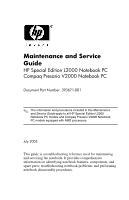
Maintenance and Service
Guide
HP Special Edition L2000 Notebook PC
Compaq Presario V2000 Notebook PC
Document Part Number: 393671-001
July 2005
This guide is a troubleshooting reference used for maintaining
and servicing the notebook. It provides comprehensive
information on identifying notebook features, components, and
spare parts; troubleshooting notebook problems; and performing
notebook disassembly procedures.
✎
The information and procedures included in this
Maintenance
and Service Guide
apply to all HP Special Edition L2000
Notebook PC models and Compaq Presario V2000 Notebook
PC models equipped with AMD processors.