HP Spectre Ultrabook 14-3210nr HP Spectre Ultrabook PC Maintenance and Service
HP Spectre Ultrabook 14-3210nr Manual
 |
View all HP Spectre Ultrabook 14-3210nr manuals
Add to My Manuals
Save this manual to your list of manuals |
HP Spectre Ultrabook 14-3210nr manual content summary:
- HP Spectre Ultrabook 14-3210nr | HP Spectre Ultrabook PC Maintenance and Service - Page 1
HP Spectre Ultrabook PC Maintenance and Service Guide IMPORTANT! This document is intended for HP authorized service providers only. - HP Spectre Ultrabook 14-3210nr | HP Spectre Ultrabook PC Maintenance and Service - Page 2
to change without notice. The only warranties for HP products and services are set forth in the express warranty statements accompanying such products and services. Nothing herein should be construed as constituting an additional warranty. HP shall not be liable for technical or editorial errors - HP Spectre Ultrabook 14-3210nr | HP Spectre Ultrabook PC Maintenance and Service - Page 3
Safety warning notice WARNING! To reduce the possibility of heat-related injuries or of overheating the device, do not place the device directly on your lap or obstruct the device air vents. Use the device only on a hard, flat surface. Do not allow another hard surface, such as an adjoining optional - HP Spectre Ultrabook 14-3210nr | HP Spectre Ultrabook PC Maintenance and Service - Page 4
iv Safety warning notice - HP Spectre Ultrabook 14-3210nr | HP Spectre Ultrabook PC Maintenance and Service - Page 5
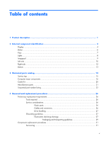
identification 4 Display ...4 Button ...6 Keys ...7 Lights ...8 Imagepad ...9 Left side ...10 Right side ...12 Bottom ...13 3 Illustrated parts catalog 14 Service tag ...15 Computer major components 16 Cable Kit ...20 Miscellaneous parts ...21 Sequential part number listing 22 4 Removal and - HP Spectre Ultrabook 14-3210nr | HP Spectre Ultrabook PC Maintenance and Service - Page 6
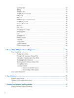
72 Updating the BIOS 72 Determining the BIOS version 73 Downloading a BIOS update 73 Using System Diagnostics ...74 6 Specifications ...75 Computer specifications ...75 14.0-inch WGA display specifications 76 7 Backing up, restoring, and recovering 77 Creating recovery media and backups 77 vi - HP Spectre Ultrabook 14-3210nr | HP Spectre Ultrabook PC Maintenance and Service - Page 7
easy recovery 80 Remove everything and reinstall Windows 81 Recovering using HP Recovery Manager 81 What you need to know 82 Using the HP Recovery partition to recover a minimized image (select models only 82 Using HP Recovery media to recover 83 Changing the computer boot order 83 Removing - HP Spectre Ultrabook 14-3210nr | HP Spectre Ultrabook PC Maintenance and Service - Page 8
viii - HP Spectre Ultrabook 14-3210nr | HP Spectre Ultrabook PC Maintenance and Service - Page 9
Chipset Graphics Panel Memory Solid-state drives Audio and video Description HP Spectre Ultrabook PC ● Intel® Core® i7-3517U 1.9-GHz processor (4.0-MB computer models equipped with the Intel HM65 Express chipset (supports HD decode, DX10, and HDMI) 14.0-in, slim light-emitting diode (LED), WVA, HD - HP Spectre Ultrabook 14-3210nr | HP Spectre Ultrabook PC Maintenance and Service - Page 10
. Full-size (14.0-in.), Island-style, no numeric keypad Radiance backlight (f5 to toggle backlight on/off) Clickpad with imaging sensor, multi-touch gestures enabled Taps enabled by default 65-W non-PFC (non-BFR/PV Free) HP Smart travel AC adapter with localized cable plug support (3-wire plug with - HP Spectre Ultrabook 14-3210nr | HP Spectre Ultrabook PC Maintenance and Service - Page 11
Category Operating system Serviceability Description Preinstalled: ● Windows® 8 Professional ● Windows 8 Standard End-user replaceable part: AC adapter 3 - HP Spectre Ultrabook 14-3210nr | HP Spectre Ultrabook PC Maintenance and Service - Page 12
2 External component identification Display Item (1) (2) (3) (4) (5) Component Internal display switch WLAN antennas (2)* Proximity sensors (2)* Internal microphones (2) Webcam light 4 Chapter 2 External component identification Description Turns off the display and initiates Sleep if the - HP Spectre Ultrabook 14-3210nr | HP Spectre Ultrabook PC Maintenance and Service - Page 13
Item Component Description (6) HP TrueVision HD webcam Records video and captures still photographs. To access the webcam, Notices that applies to your country or region. To access this guide, select the HP Support Assistant app from the Start screen, select My computer, and then select User - HP Spectre Ultrabook 14-3210nr | HP Spectre Ultrabook PC Maintenance and Service - Page 14
Button Component Power button Description ● When the computer is off, press the button to turn on the computer. ● When the computer is on, press the button briefly to initiate Sleep. ● When the computer is in the Sleep state, press the button briefly to exit Sleep. ● When the computer is in - HP Spectre Ultrabook 14-3210nr | HP Spectre Ultrabook PC Maintenance and Service - Page 15
Keys Item (1) (2) Component esc key fn key (3) Windows logo key (4) Action keys (5) b key (6) Windows applications key Description Displays system information when pressed in combination with the fn key. Executes the following functions: ● When the key is pressed in combination with the - HP Spectre Ultrabook 14-3210nr | HP Spectre Ultrabook PC Maintenance and Service - Page 16
Lights Item (1) (2) (3) (4) Component Power light Caps lock light Keyboard backlight light Wireless light (5) Imagepad light (6) Beats Audio light (7) Mute light 8 Chapter 2 External component identification Description ● White: The computer is on. ● Blinking white: The computer is in the - HP Spectre Ultrabook 14-3210nr | HP Spectre Ultrabook PC Maintenance and Service - Page 17
Imagepad Item (1) (2) (3) (4) (5) Component Imagepad light Imagepad on/off button Left Imagepad button Imagepad zone Right Imagepad button Description ● Amber: The Imagepad is off. ● On: The Imagepad is on. Quickly double-tap this button to turn the Imagepad off or on. The bottom left corner of - HP Spectre Ultrabook 14-3210nr | HP Spectre Ultrabook PC Maintenance and Service - Page 18
enable this feature in Setup Utility. For information on enabling features in Setup utility, see the "Setup Utility (BIOS) and System Diagnostics" chapter in the HP Notebook Reference Guide. 10 Chapter 2 External component identification - HP Spectre Ultrabook 14-3210nr | HP Spectre Ultrabook PC Maintenance and Service - Page 19
jack, the computer speakers are disabled. NOTE: Be sure that the device cable has a 4-conductor connector that supports both audio-out (headphone) and audio-in (microphone). Supports the following digital card formats: ● MultiMediaCard ● Secure Digital (SD) Memory Card ● Secure Digital High Capacity - HP Spectre Ultrabook 14-3210nr | HP Spectre Ultrabook PC Maintenance and Service - Page 20
Hard Drive Protection has temporarily parked the hard drive. NOTE: For information about HP ProtectSmart Hard Drive Protection, see the HP Notebook Reference Guide. ● White: The computer is on. ● Blinking white: The computer is in the Sleep state. ● Off: The computer is off or in Hibernation - HP Spectre Ultrabook 14-3210nr | HP Spectre Ultrabook PC Maintenance and Service - Page 21
Item (7) Component AC adapter light (8) Bottom Power connector Description ● White: The computer is connected to external power, and the battery is fully charged. ● Amber: The computer is connected to external power, and the battery is charging. ● Blinking amber: The computer is connected to - HP Spectre Ultrabook 14-3210nr | HP Spectre Ultrabook PC Maintenance and Service - Page 22
3 Illustrated parts catalog 14 Chapter 3 Illustrated parts catalog - HP Spectre Ultrabook 14-3210nr | HP Spectre Ultrabook PC Maintenance and Service - Page 23
the computer serial number and model description provided on the service tag. Item (1) (2) (3) Description Product name Serial number information about the product's hardware components. The part number helps a service technician to determine what components and parts are needed. This number - HP Spectre Ultrabook 14-3210nr | HP Spectre Ultrabook PC Maintenance and Service - Page 24
Computer major components 16 Chapter 3 Illustrated parts catalog - HP Spectre Ultrabook 14-3210nr | HP Spectre Ultrabook PC Maintenance and Service - Page 25
Item (1) (2) (3) (4) Component Spare part number Display assembly, 14.0-in, AntiGlare, high-definition (includes display panel cable, 675507-001 2 WLAN antenna transceivers and cables, and webcam/microphone module and cable) Top cover with keyboard ( - HP Spectre Ultrabook 14-3210nr | HP Spectre Ultrabook PC Maintenance and Service - Page 26
Item (5) (6a) (6b) (7) (8) (9) (10) (11) (12) (13) (14) (15) (16) Component Spare part number NFC board 675510-001 NOTE: The NFC board spare part kit does not include the NFC board cable. The - HP Spectre Ultrabook 14-3210nr | HP Spectre Ultrabook PC Maintenance and Service - Page 27
Item (17) (18) (19) (20) (21) (22) (23) (24) Component Spare part number Memory module (PC3, 12800, 1333-MHz): 8-GB memory module 670034-005 4-GB memory module 641369-005 Heat sink (includes replacement thermal material): Processor heat sink 675514-001 Post controller hub heat sink - HP Spectre Ultrabook 14-3210nr | HP Spectre Ultrabook PC Maintenance and Service - Page 28
Cable Kit Item (1) (2) (3) Component Cable Kit, includes: TouchPad cable NFC board cable Card Reader board cable Spare part number 672006-001 20 Chapter 3 Illustrated parts catalog - HP Spectre Ultrabook 14-3210nr | HP Spectre Ultrabook PC Maintenance and Service - Page 29
travel AC adapter HDMI-to-VGA adapter HP 14.0-in protective cover USB external DVD±RW DL SuperMulti Drive Power cord (3-pin, black, 1.83-m): For use in Australia For use in Denmark For use - HP Spectre Ultrabook 14-3210nr | HP Spectre Ultrabook PC Maintenance and Service - Page 30
Israel (3-pin, black, 1.83-m) 490371-D61 Power cord for use in India (3-pin, black, 1.83-m) 530607-001 HDMI-to-VGA adapter 574638-001 65-W HP Smart travel AC adapter 636672-005 Intel Centrino Advanced-N 6230 WLAN module 641369-005 4-GB memory module (PC3, 12800, 1600-MHz) 659940-001 USB - HP Spectre Ultrabook 14-3210nr | HP Spectre Ultrabook PC Maintenance and Service - Page 31
and wireless audio module antenna cables) 672016-001 Rubber Feet Kit (includes front and rear rubber feet) 674766-001 HP 14.0-in protective cover 675507-001 14.0-in, AntiGlare, high-definition display assembly (includes display panel cable, 2 WLAN antenna transceivers and cables, and webcamera - HP Spectre Ultrabook 14-3210nr | HP Spectre Ultrabook PC Maintenance and Service - Page 32
Spare part number Description 698466-601 System board equipped with the Intel HM76 chipset and Intel Core i7-3517U 1.9-GHz processor for use only on computer models equipped with Windows 8 Professional in all countries and regions except the People's Republic of China (4.0-MB L3 cache, 17 W; - HP Spectre Ultrabook 14-3210nr | HP Spectre Ultrabook PC Maintenance and Service - Page 33
Spare part number Description 698632-BG1 Top cover with keyboard for use only on computer models equipped with Windows 8 in Switzerland (includes keyboard cable, TouchPad, and TouchPad button board and cable) 698632-DB1 Top cover with keyboard for use only on computer models equipped with - HP Spectre Ultrabook 14-3210nr | HP Spectre Ultrabook PC Maintenance and Service - Page 34
computer does not have user-replaceable parts. Only HP authorized service providers should perform the removal and replacement procedures described only at the points designated in the maintenance instructions. Cables and connectors CAUTION: When servicing the computer, be sure that cables are placed - HP Spectre Ultrabook 14-3210nr | HP Spectre Ultrabook PC Maintenance and Service - Page 35
Cables must be handled with extreme care to avoid damage. Apply only the tension required to unseat or seat the cables during removal and insertion. Handle cables by the connector whenever possible. In all cases, avoid bending, twisting, or tearing cables. Be sure that cables are routed in such a - HP Spectre Ultrabook 14-3210nr | HP Spectre Ultrabook PC Maintenance and Service - Page 36
box Typical electrostatic voltage levels Relative humidity 10% 40% 35,000 V 15,000 V 12,000 V 5,000 V 6,000 V 800 V 2,000 V 700 V 11,500 V 4,000 V 14,500 V 5,000 V 26,500 V 20,000 V 21,000 V 11,000 V 55% 7,500 V 3,000 V 400 V 400 V 2,000 V 3,500 V 7,000 V 5,000 V 28 Chapter - HP Spectre Ultrabook 14-3210nr | HP Spectre Ultrabook PC Maintenance and Service - Page 37
. ● Use a wrist strap connected to a properly grounded work surface and use properly grounded tools and equipment. ● Use conductive field service tools, such as cutters, screwdrivers, and vacuums. ● When fixtures must directly contact dissipative surfaces, use fixtures made only of staticsafe - HP Spectre Ultrabook 14-3210nr | HP Spectre Ultrabook PC Maintenance and Service - Page 38
with ground cords of one megohm resistance ● Static-dissipative tables or floor mats with hard ties to the ground ● Field service kits ● Static awareness labels ● Material-handling packages ● Nonconductive plastic bags, tubes, or boxes ● Metal tote boxes ● Electrostatic voltage levels and - HP Spectre Ultrabook 14-3210nr | HP Spectre Ultrabook PC Maintenance and Service - Page 39
, provide the computer serial number and model number provided on the service tag. It is necessary to remove the battery to obtain these numbers. See Battery on page 33 for battery removal instructions. Item (1) (2) (3) Component Product name Serial number (s/n) Part number/Product number - HP Spectre Ultrabook 14-3210nr | HP Spectre Ultrabook PC Maintenance and Service - Page 40
This number describes the duration of the warranty period for the computer. This is the alphanumeric identifier used to locate documents, drivers, and support for the computer. Computer feet The computer feet are adhesive-backed rubber pads. There are 2 rubber feet that attach to the battery cover - HP Spectre Ultrabook 14-3210nr | HP Spectre Ultrabook PC Maintenance and Service - Page 41
Battery Description 4-cell, 58-Wh, 4.1-Ah, Li-ion battery Spare part number 665460-001 Before disassembling the computer, follow these steps: 1. Turn off the computer. If you are unsure whether the computer is off or in Hibernation, turn the computer on, and then shut it down through the operating - HP Spectre Ultrabook 14-3210nr | HP Spectre Ultrabook PC Maintenance and Service - Page 42
8. Remove the battery (4) from the computer. Reverse this procedure to install the battery and battery cover. 34 Chapter 4 Removal and replacement procedures - HP Spectre Ultrabook 14-3210nr | HP Spectre Ultrabook PC Maintenance and Service - Page 43
Solid-state drive Description 256-GB SATA III solid-state drive 128-GB SATA III solid-state drive 128-GB SATA II solid-state drive Spare part number 698645-001 697235-001 675508-001 Before removing the solid-state drive and cable, follow these steps: 1. Turn off the computer. If you are unsure - HP Spectre Ultrabook 14-3210nr | HP Spectre Ultrabook PC Maintenance and Service - Page 44
3. If it is necessary to replace the solid-state drive connector board cable, disconnect both ends of the cable (1) and (2) from the system board, and then release the cable from the clips (3) and channel built into the base enclosure. The solid-state drive connector board cable is included in the - HP Spectre Ultrabook 14-3210nr | HP Spectre Ultrabook PC Maintenance and Service - Page 45
Card Reader board cable NOTE: The Card Reader board cable is included in the Cable Kit, spare part number 672006-001. Before removing the Card Reader board cable, follow these steps: 1. Turn off the computer. If you are unsure whether the computer is off or in Hibernation, turn the computer on, and - HP Spectre Ultrabook 14-3210nr | HP Spectre Ultrabook PC Maintenance and Service - Page 46
NFC board Description Spare part number NFC board 675510-001 NOTE: The NFC board spare part kit does not include the NFC board cable. The NFC board cable is included in the Cable Kit, spare part number 672006-001. Before removing the NFC board, follow these steps: 1. Turn off the computer. If - HP Spectre Ultrabook 14-3210nr | HP Spectre Ultrabook PC Maintenance and Service - Page 47
3. Release the ZIF connector to which the NFC board cable is attached, and then disconnect the NFC board cable from the system board. 4. Remove the NFC board. Reverse this procedure to install the NFC board. Component replacement procedures 39 - HP Spectre Ultrabook 14-3210nr | HP Spectre Ultrabook PC Maintenance and Service - Page 48
Top cover NOTE: The top cover spare part kit includes the keyboard, the keyboard cable, the TouchPad board cable, and the TouchPad button board cable. Description For use in Belgium For use in Canada For use in Denmark, Finland, and Norway For use in France For use in Germany For use in Greece For - HP Spectre Ultrabook 14-3210nr | HP Spectre Ultrabook PC Maintenance and Service - Page 49
5. Remove the solid-state drive connector board cable (see Solid-state drive on page 35). 6. Remove the Card Reader board cable (see Card Reader board cable on page 37). NOTE: When replacing the top cover, be sure to remove the following components from the defective top cover and install them on - HP Spectre Ultrabook 14-3210nr | HP Spectre Ultrabook PC Maintenance and Service - Page 50
4. Remove the following screws that secure the top cover to the base enclosure: (2) Two Phillips PM2.0×5.5 (3) Five Phillips PM2.0×4.5 (4) Four Phillips PM2.0×4.0 5. Turn the computer right side up, with the front toward you. 6. Open the computer. 7. Lift the front edge of the top cover slightly, - HP Spectre Ultrabook 14-3210nr | HP Spectre Ultrabook PC Maintenance and Service - Page 51
8. Release the ZIF connector (1) to which the power button board cable is connected, and then disconnect the power button board cable (2) from the system board. 9. Release the ZIF connector (3) to which the keyboard cable is connected, and then disconnect the keyboard cable (4) from the system board - HP Spectre Ultrabook 14-3210nr | HP Spectre Ultrabook PC Maintenance and Service - Page 52
Reverse this procedure to install the top cover. Solid-state drive connector board Description Solid-state drive connector board (includes cable) Spare part number 675509-001 Before removing the solid-state drive connector board, follow these steps: 1. Turn off the computer. If you are unsure - HP Spectre Ultrabook 14-3210nr | HP Spectre Ultrabook PC Maintenance and Service - Page 53
3. Remove the solid-state drive connector board (2). Reverse this procedure to install the solid-state drive connector board. Card Reader board NOTE: The Card Reader board spare part kit does not include the Card Reader board cable. The Card Reader board cable is included in the Cable Kit, spare - HP Spectre Ultrabook 14-3210nr | HP Spectre Ultrabook PC Maintenance and Service - Page 54
Remove the Card Reader board: 1. Turn the top cover upside down, with the front toward you. 2. Remove the two Phillips PM2.0×3.6 screws (1) and the Phillips PM2.0×3.2 screw (2) that secure the Card Reader board to the top cover. 3. Lift the left side of the Card Reader board (3) until it rests at an - HP Spectre Ultrabook 14-3210nr | HP Spectre Ultrabook PC Maintenance and Service - Page 55
3. Disconnect all external devices from the computer. 4. Remove the battery (see Battery on page 33), and then remove the following components: a. Solid-state drive connector board cable (see Solid-state drive on page 35) b. Card Reader board cable (see Card Reader board cable on page 37) c. Top - HP Spectre Ultrabook 14-3210nr | HP Spectre Ultrabook PC Maintenance and Service - Page 56
Speakers Description Speakers (include speaker cables and wireless audio module antenna cables) Spare part number 672013-001 Before removing the speakers, follow these steps: 1. Turn off the computer. If you are unsure whether the computer is off or in Hibernation, turn the computer on, and then - HP Spectre Ultrabook 14-3210nr | HP Spectre Ultrabook PC Maintenance and Service - Page 57
3. Remove the two Phillips PM2.0×3.8 screws (1) that secure the speakers to the base enclosure. 4. Remove the speakers (2). Reverse this procedure to install the speakers. RTC battery Description RTC battery (double-sided tape and cable) Spare part number 672013-001 Before removing the RTC - HP Spectre Ultrabook 14-3210nr | HP Spectre Ultrabook PC Maintenance and Service - Page 58
Remove the RTC battery: 1. Disconnect the RTC battery cable (1) from the system board. 2. Detach the RTC battery (2) from the base enclosure. (The RTC battery is attached to the base enclosure with double-sided tape). 3. Release the RTC battery cable from the clips (3) and routing channel built into - HP Spectre Ultrabook 14-3210nr | HP Spectre Ultrabook PC Maintenance and Service - Page 59
Wireless audio module Description Wireless audio module Spare part number 672011-001 Before removing the wireless audio module, follow these steps: 1. Turn off the computer. If you are unsure whether the computer is off or in Hibernation, turn the computer on, and then shut it down through the - HP Spectre Ultrabook 14-3210nr | HP Spectre Ultrabook PC Maintenance and Service - Page 60
3. Remove the wireless audio module by pulling the module away from the slot at an angle (3). NOTE: The wireless audio module is designed with a notch to prevent incorrect installation into the wireless audio module slot. NOTE: If the wireless audio module antennas are not connected to the terminals - HP Spectre Ultrabook 14-3210nr | HP Spectre Ultrabook PC Maintenance and Service - Page 61
country or region. If you replace the module and then receive a warning message, remove the module to restore device functionality, and then contact technical support. Before removing the WLAN module, follow these steps: 1. Turn off the computer. If you are unsure whether the computer is off or in - HP Spectre Ultrabook 14-3210nr | HP Spectre Ultrabook PC Maintenance and Service - Page 62
3. Remove the WLAN module by pulling the module away from the slot at an angle (3). NOTE: The WLAN module is designed with a notch (4) to prevent incorrect installation into the WLAN module slot. NOTE: If the WLAN antennas are not connected to the terminals on the WLAN module, the protective sleeves - HP Spectre Ultrabook 14-3210nr | HP Spectre Ultrabook PC Maintenance and Service - Page 63
Fan Description Fan (includes cable) Spare part number 672008-001 NOTE: To properly ventilate the computer, allow at least 7.6 cm (3 in) of clearance on the left side of the computer. The computer uses an electric fan for ventilation. The fan is controlled by a temperature sensor and is designed - HP Spectre Ultrabook 14-3210nr | HP Spectre Ultrabook PC Maintenance and Service - Page 64
3. Remove the fan (4). Reverse this procedure to install the fan. 56 Chapter 4 Removal and replacement procedures - HP Spectre Ultrabook 14-3210nr | HP Spectre Ultrabook PC Maintenance and Service - Page 65
System board NOTE: The system board spare part kit includes replacement thermal material. Description Spare part number Equipped with the Intel HM76 chipset and Intel Core i7-3517U 1.9-GHz processor for use only on 698466-601 computer models equipped with the Windows 8 Professional operating - HP Spectre Ultrabook 14-3210nr | HP Spectre Ultrabook PC Maintenance and Service - Page 66
When replacing the system board, be sure that the following components are removed from the defective system board and installed on the replacement system board: ● Fans (see Fan on page 55) ● Memory module (see Memory module on page 60) ● Heat sink (see Heat sink on page 61) Remove the system board: - HP Spectre Ultrabook 14-3210nr | HP Spectre Ultrabook PC Maintenance and Service - Page 67
4. Remove the following screws that secure the system board to the base enclosure: (1) Five Phillips PM2.0×3.8 (2) Four Phillips PM2.0×4.6 (3) One Phillips PM2.0×5.7 5. Lift the right side of the system board (1) until it rests at an angle. 6. Disconnect the power connector cable (2) from the system - HP Spectre Ultrabook 14-3210nr | HP Spectre Ultrabook PC Maintenance and Service - Page 68
Memory module Description 8-GB memory module (PC3, 12800, 1333-MHz) 4-GB memory module (PC3, 12800, 1333-MHz) Spare part number 670034-005 641369-005 Before removing the memory module, follow these steps: 1. Turn off the computer. If you are unsure whether the computer is off or in Hibernation, - HP Spectre Ultrabook 14-3210nr | HP Spectre Ultrabook PC Maintenance and Service - Page 69
3. Remove the memory module (2) by pulling it away from the slot at an angle. Reverse this procedure to install the memory module. Heat sink NOTE: The heat sink spare part kits include replacement thermal material. Description Processor heat sink Post controller hub heat sink Spare part number - HP Spectre Ultrabook 14-3210nr | HP Spectre Ultrabook PC Maintenance and Service - Page 70
them on the replacement heat sink. See Fan on page 55 for fan removal and replacement instructions. Remove the processor heat sink: 1. Following the 1, 2, 3, 4 sequence stamped into the (1) and the processor heat sink section (2) that services it. 62 Chapter 4 Removal and replacement procedures - HP Spectre Ultrabook 14-3210nr | HP Spectre Ultrabook PC Maintenance and Service - Page 71
Reverse this procedure to install the processor heat sink. Remove the post controller hub heat sink: 1. Loosen the captive Philllips screw (1) that secures the post controller hub heat sink to the system board. 2. Remove the post controller hub heat sink (2). NOTE: Due to the adhesive quality of the - HP Spectre Ultrabook 14-3210nr | HP Spectre Ultrabook PC Maintenance and Service - Page 72
NOTE: The following illustration shows the replacement thermal material locations. A thermal pad is used on the post controller hub (1) and the post controller hub heat sink (2). Reverse this procedure to install the post controller hub heat sink. 64 Chapter 4 Removal and replacement procedures - HP Spectre Ultrabook 14-3210nr | HP Spectre Ultrabook PC Maintenance and Service - Page 73
Hinge covers Description Hinge covers Spare part number 672009-001 Before removing the hinge covers, follow these steps: 1. Turn off the computer. If you are unsure whether the computer is off or in Hibernation, turn the computer on, and then shut it down through the operating system. 2. - HP Spectre Ultrabook 14-3210nr | HP Spectre Ultrabook PC Maintenance and Service - Page 74
the hinge covers (2) from the base enclosure. Reverse this procedure to install the hinge covers. Display assembly Description Display assembly, 14.0-in, AntiGlare, high-definition (includes display panel cable, 2 WLAN antenna transceivers and cables, and webcam/microphone module and cable) Spare - HP Spectre Ultrabook 14-3210nr | HP Spectre Ultrabook PC Maintenance and Service - Page 75
heat sink. (The display panel cable is attached to the heat sink with double-sided tape.) CAUTION: Support the display assembly when removing the following screws. Failure to support the display assembly can result in damage to the display assembly and other computer components. 4. Remove the six - HP Spectre Ultrabook 14-3210nr | HP Spectre Ultrabook PC Maintenance and Service - Page 76
5. Remove the display assembly (2). Reverse this procedure to install the display assembly. Power connector cable Description Power connector cable Spare part number 687530-001 Before removing the power connector cable, follow these steps: 1. Turn off the computer. If you are unsure whether the - HP Spectre Ultrabook 14-3210nr | HP Spectre Ultrabook PC Maintenance and Service - Page 77
f. System board (see System board on page 57) g. Display assembly (see Display assembly on page 66) Remove the power connector cable: 1. Remove the Phillips PM2.0×3.8 screw (1) that secures the power connector and bracket to the base enclosure. 2. Remove the power connector bracket (2). 3. Remove - HP Spectre Ultrabook 14-3210nr | HP Spectre Ultrabook PC Maintenance and Service - Page 78
operating properly. Starting Setup Utility NOTE: An external keyboard or mouse connected to a USB port can be used with Setup Utility only if USB legacy support is enabled. To start Setup Utility, follow these steps: 1. Turn on or restart the computer, and then press esc while the "Press the ESC key - HP Spectre Ultrabook 14-3210nr | HP Spectre Ultrabook PC Maintenance and Service - Page 79
select Exit > Exit Discarding Changes, and then press enter. ● To save your changes and exit Setup Utility menus, press f10, and then follow the onscreen instructions. - or - Use the tab key and the arrow keys to select Exit > Exit Saving Changes, and then press enter. Your changes go into effect - HP Spectre Ultrabook 14-3210nr | HP Spectre Ultrabook PC Maintenance and Service - Page 80
the BIOS may be available on the HP Web site. Most BIOS updates on the HP Web site are packaged in compressed files called SoftPaqs. Some download packages contain a file named Readme.txt, which contains information regarding installing and troubleshooting the file. 72 Chapter 5 Setup Utility (BIOS - HP Spectre Ultrabook 14-3210nr | HP Spectre Ultrabook PC Maintenance and Service - Page 81
, or disconnect any device, cable, or cord. 1. Windows 7-Select Start > Help and Support > Maintain. Windows XP-Select Start > Help and Support, and then select the software and drivers update. 2. Follow the on-screen instructions to identify your computer and access the BIOS update you want to - HP Spectre Ultrabook 14-3210nr | HP Spectre Ultrabook PC Maintenance and Service - Page 82
repeats the start-up test and checks for intermittent problems that the start-up test does not detect. If the battery fails the test, contact HP support to report the issue and purchase a to run, and then follow the on-screen instructions. NOTE: If you need to stop a diagnostics test while - HP Spectre Ultrabook 14-3210nr | HP Spectre Ultrabook PC Maintenance and Service - Page 83
6 Specifications Computer specifications Metric U.S. Dimensions Width 32.72 cm 12.88 in Depth 22.10 cm 8.70 in Height 2.05 cm 0.81 in Weight 1.80 kg 3.97 lb Input power Operating voltage and current 19.5 V dc @ 3.33 A - 65W Temperature Operating 5°C to 35°C 41°F to 95°F - HP Spectre Ultrabook 14-3210nr | HP Spectre Ultrabook PC Maintenance and Service - Page 84
14.0-inch WGA display specifications Dimensions Height Width Diagonal Number of colors Contrast ratio Brightness Pixel resolution Pitch Format Configuration Backlight Character display Total power consumption - HP Spectre Ultrabook 14-3210nr | HP Spectre Ultrabook PC Maintenance and Service - Page 85
your system NOTE: This guide describes an overview of backing Support. Creating recovery media and backups Recovery after a system failure is only as good as your most recent backup. 1. After you successfully set up the computer, create HP Recovery media. This step creates a backup of the HP - HP Spectre Ultrabook 14-3210nr | HP Spectre Ultrabook PC Maintenance and Service - Page 86
software update, security scanning, or system diagnostics). You can also manually create a system restore point at any time. For more your computer from the HP website. For U.S. support, go to http://www.hp.com/go/contactHP. For worldwide support, go to http://welcome.hp.com/country/us/en/ - HP Spectre Ultrabook 14-3210nr | HP Spectre Ultrabook PC Maintenance and Service - Page 87
Support. ● If you need to correct a problem with a preinstalled application or driver, use the Drivers and Applications Reinstall option of HP HP Recovery Manager, and then select Drivers and Applications Reinstall, and follow the on-screen instructions if you did not manually create a restore point, - HP Spectre Ultrabook 14-3210nr | HP Spectre Ultrabook PC Maintenance and Service - Page 88
choose the System Recovery option from the HP Recovery media. For more information, see the "Recovering using HP Recovery Manager" section. ● If See Help and Support for instructions on reinstalling traditional applications. From the Start screen, type h, and then select Help and Support. NOTE: You - HP Spectre Ultrabook 14-3210nr | HP Spectre Ultrabook PC Maintenance and Service - Page 89
press the power button. 2. Select Troubleshoot from the boot options menu. 3. Select Reset your PC, and follow the on-screen instructions. To use the Start screen: 1. started, and follow the on-screen instructions. Recovering using HP Recovery Manager HP Recovery Manager software allows you to - HP Spectre Ultrabook 14-3210nr | HP Spectre Ultrabook PC Maintenance and Service - Page 90
working. To start HP Recovery Manager from the HP Recovery partition: 1. Press f11 while the computer boots. - or - Press and hold f11 as you press the power button. 2. Select Troubleshoot from the boot options menu. 3. Select HP Recovery Manager, and follow the on-screen instructions. 82 Chapter - HP Spectre Ultrabook 14-3210nr | HP Spectre Ultrabook PC Maintenance and Service - Page 91
, change the computer boot order. See the "Changing the computer boot order" section. 3. Follow the on-screen instructions. Changing the computer boot order If computer does not restart in HP Recovery Manager, you can change the computer boot order, which is the order of devices listed in BIOS where - HP Spectre Ultrabook 14-3210nr | HP Spectre Ultrabook PC Maintenance and Service - Page 92
8 Power cord set requirements The wide-range input feature of the computer permits it to operate from any line voltage from 100 to 120 volts AC, or from 220 to 240 volts AC. The 3-conductor power cord set included with the computer meets the requirements for use in the country or region where the - HP Spectre Ultrabook 14-3210nr | HP Spectre Ultrabook PC Maintenance and Service - Page 93
Requirements for specific countries and regions Country/region Accredited agency Applicable note number Australia EANSW 1 Austria OVE 1 Belgium CEBC 1 Canada CSA 2 Denmark DEMKO 1 Finland FIMKO 1 France UTE 1 Germany VDE 1 Italy IMQ 1 Japan METI 3 The Netherlands - HP Spectre Ultrabook 14-3210nr | HP Spectre Ultrabook PC Maintenance and Service - Page 94
dispose of the battery in general household waste. Follow the local laws and regulations in your area for battery disposal. HP encourages customers to recycle used electronic hardware, HP original print cartridges, and rechargeable batteries. For more information about recycling programs, see the - HP Spectre Ultrabook 14-3210nr | HP Spectre Ultrabook PC Maintenance and Service - Page 95
button component 6 buttons Beats Audio 12 Imagepad 9 Imagepad on/off 9 mute 12 power 6 C Cable Kit contents 20 spare part number 20, 22 cables, service considerations 26 caps lock light 8 Card Reader board removal 45 spare part number 45 spare part numbers 17, 23 Card Reader board cable illustrated - HP Spectre Ultrabook 14-3210nr | HP Spectre Ultrabook PC Maintenance and Service - Page 96
, 23, 38 O operating system, product description 3 optical drive precautions 27 spare part number 21, 22 P packaging guidelines 29 plastic parts, service considerations 26 pointing device, product description 2 ports DisplayPort 10 HDMI 10 product description 2 USB 10 post controller hub heat sink - HP Spectre Ultrabook 14-3210nr | HP Spectre Ultrabook PC Maintenance and Service - Page 97
part number 21, 22 security cable slot 12 security, product description 2 serial number 31 service considerations cables 26 connectors 26 plastic parts 26 service tag 15, 31 serviceability, product description 3 solid-state drive precautions 27 product description 1 removal 35 spare part number - HP Spectre Ultrabook 14-3210nr | HP Spectre Ultrabook PC Maintenance and Service - Page 98
-
 1
1 -
 2
2 -
 3
3 -
 4
4 -
 5
5 -
 6
6 -
 7
7 -
8
-
9
-
10
-
11
-
12
-
13
-
14
-
15
-
16
-
17
-
18
-
19
-
20
-
21
-
22
-
23
-
24
-
25
-
26
-
27
-
28
-
29
-
30
-
31
-
32
-
33
-
34
-
35
-
36
-
37
-
38
-
39
-
40
-
41
-
42
-
43
-
44
-
45
-
46
-
47
-
48
-
49
-
50
-
51
-
52
-
53
-
54
-
55
-
56
-
57
-
58
-
59
-
60
-
61
-
62
-
63
-
64
-
65
-
66
-
67
-
68
-
69
-
70
-
71
-
72
-
73
-
74
-
75
-
76
-
77
-
78
-
79
-
80
-
81
-
82
-
83
-
84
-
85
-
86
-
87
-
88
-
89
-
90
-
91
-
92
-
93
-
94
-
95
-
96
-
97
-
98
 |
 |

HP Spectre Ultrabook PC
Maintenance and Service Guide
IMPORTANT! This document is intended for
HP authorized service providers only.