HP Split 13-m200 HP Split 13 x2 PC Maintenance and Service Guide
HP Split 13-m200 Manual
 |
View all HP Split 13-m200 manuals
Add to My Manuals
Save this manual to your list of manuals |
HP Split 13-m200 manual content summary:
- HP Split 13-m200 | HP Split 13 x2 PC Maintenance and Service Guide - Page 1
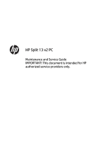
HP Split 13 x2 PC Maintenance and Service Guide IMPORTANT! This document is intended for HP authorized service providers only. - HP Split 13-m200 | HP Split 13 x2 PC Maintenance and Service Guide - Page 2
-001 Product notice This guide describes features that are common to most models. Some features may not be available on your computer. Not all features are available in all editions of Windows 8. Your computer may require upgraded and/or separately purchased hardware, drivers, and/or software to - HP Split 13-m200 | HP Split 13 x2 PC Maintenance and Service Guide - Page 3
Self-Repair Parts CAUTION: Your computer includes parts that should only be accessed by an authorized service provider. Accessing parts described in the chapter titled, "Removal and replacement procedures for Authorized Service Provider only parts," can damage the computer or void your warranty. iii - HP Split 13-m200 | HP Split 13 x2 PC Maintenance and Service Guide - Page 4
iv Important Notice about Customer Self-Repair Parts - HP Split 13-m200 | HP Split 13 x2 PC Maintenance and Service Guide - Page 5
Safety warning notice WARNING! To reduce the possibility of heat-related injuries or of overheating the device, do not place the device directly on your lap. Use the device only on a hard, flat surface. Do not allow another hard surface, such as an adjoining optional printer, or a soft surface, such - HP Split 13-m200 | HP Split 13 x2 PC Maintenance and Service Guide - Page 6
vi Safety warning notice - HP Split 13-m200 | HP Split 13 x2 PC Maintenance and Service Guide - Page 7
...16 3 Illustrated parts catalog ...17 Tablet components ...17 Keyboard dock parts ...20 Miscellaneous parts ...22 Sequential part number listing ...23 4 Removal and replacement procedures preliminary requirements 27 Tools required ...27 Service considerations ...27 Plastic parts ...27 Cables and - HP Split 13-m200 | HP Split 13 x2 PC Maintenance and Service Guide - Page 8
Bottom trim ...61 Home LED board ...63 Audio board ...64 Card reader ...66 Speakers ...67 Battery ...68 Frame ...69 Webcam ...70 System board ...72 Vibration module ...74 6 Using Setup Utility the BIOS version ...76 Downloading a BIOS update ...77 Using HP PC Hardware Diagnostics (UEFI) ...77 viii - HP Split 13-m200 | HP Split 13 x2 PC Maintenance and Service Guide - Page 9
79 33.8-cm (13.3-in), HD display specifications ...80 8 Backing up, restoring, and recovering ...81 Creating recovery media and backups ...81 Creating HP Recovery media ...82 Restore and recovery ...82 Using Windows Refresh for quick and easy recovery 83 Remove everything and reinstall Windows 84 - HP Split 13-m200 | HP Split 13 x2 PC Maintenance and Service Guide - Page 10
Chipset Graphics Panel Memory Storage Description HP Split 13 x2 PC Intel® Core™ i5-4210Y Supports 16:9 wide aspect ratio Support for eDP, touchscreen, multi-touch enabled Supports up to 8-GB system memory No support for 32-bit operating system DDR3L-1600-MHz, single channel support Supports - HP Split 13-m200 | HP Split 13 x2 PC Maintenance and Service Guide - Page 11
Micro Secure Digital (SD) Media Reader Push-push insertion/removal Base: HP Multi-Format Digital Media Reader Push-push insertion/removal One half-size v1.4a supporting up to 1080p @ 60 Hz Full size, dura coat, island-style keyboard Taps enabled as default Clickpad with image sensor Supports Windows - HP Split 13-m200 | HP Split 13 x2 PC Maintenance and Service Guide - Page 12
m Serviceability Description Multi-touch gestures enabled Supports the following HP AC adapters: 45-W Smart nPFC, 3-pin, 4.5-mm connector, 90-degree plug design 65-W EM Smart nPFC, 3-pin, 4.5-mm connector, 90-degree plug design 1 meter (3.3 ft) length power cord Tablet: 3-cell, 33 WHr battery (self - HP Split 13-m200 | HP Split 13 x2 PC Maintenance and Service Guide - Page 13
. NOTE: When a device is connected to the jack, the computer speakers are disabled. NOTE: Be sure that the device cable has a 4-conductor connector that supports both audio-out (headphone) and audio-in (microphone). NOTE: Stand-alone microphones and headphones with separate microphone jacks are not - HP Split 13-m200 | HP Split 13 x2 PC Maintenance and Service Guide - Page 14
(4) (5) (6) Description Internal microphones (2) Webcam light HP TrueVision Full HD Webcam Ambient light sensor Speakers (2) tap CyberLink YouCam from the list of applications. - or - From the Start screen, type c, and then select CyberLink YouCam from the list of applications. Automatically adjusts - HP Split 13-m200 | HP Split 13 x2 PC Maintenance and Service Guide - Page 15
Control Panel. To open Beats Audio Control Panel, from the Start screen on the keyboard dock, type c, select Control Panel, select Hardware and Sound, NOTE: Be sure that the device cable has a 4conductor connector that supports both audioout (headphone) and audio-in (microphone). NOTE: Stand-alone - HP Split 13-m200 | HP Split 13 x2 PC Maintenance and Service Guide - Page 16
about your power settings, on the Start screen, type p. In the search box, type power, select Settings, and then select Power options. Align and attach the tablet to the keyboard dock. Connects an AC adapter. ● White: The AC adapter is connected and the battery is charged. Tablet edge components 7 - HP Split 13-m200 | HP Split 13 x2 PC Maintenance and Service Guide - Page 17
battery has reached a low battery level. ● Amber: The AC adapter is connected and the battery is charging. ● Off: The computer is using DC power. Connects the tablet to the keyboard and headphones with separate microphone jacks are not supported. Supports micro Secure Digital (SD) memory cards. - HP Split 13-m200 | HP Split 13 x2 PC Maintenance and Service Guide - Page 18
(4) WLAN antennas (2)* Internal microphones (2) Webcam light HP TrueVision Full HD Webcam Description Send and receive wireless tap CyberLink YouCam from the list of applications. - or - From the Start screen, type c, and then select CyberLink YouCam from the list of applications. (5) Ambient - HP Split 13-m200 | HP Split 13 x2 PC Maintenance and Service Guide - Page 19
posts Release latch Docking connector Description Align and attach the tablet to the keyboard dock. Releases the tablet from the keyboard dock. To release the tablet, slide the release latch to the left. Connects the tablet to the keyboard dock. 10 Chapter 2 External component identification - HP Split 13-m200 | HP Split 13 x2 PC Maintenance and Service Guide - Page 20
TouchPad Component (1) TouchPad zone (2) Left TouchPad button (3) Right TouchPad button Description Reads your finger gesture to move the pointer or activate items on the screen. Functions like the left button of an external mouse. Functions like the right button on an external mouse. - HP Split 13-m200 | HP Split 13 x2 PC Maintenance and Service Guide - Page 21
Lights Component (1) Caps lock light (2) Mute light (3) Wireless light Description ● White: Caps lock is on. ● Off: Caps lock is off. ● Amber: Computer sound is off. ● Off: Computer sound is on. ● White: An integrated wireless device, such as a wireless local area network (WLAN) device and/or - HP Split 13-m200 | HP Split 13 x2 PC Maintenance and Service Guide - Page 22
desktop. NOTE: Pressing the Windows key again returns you to the previous screen. Enables or disables Beats Audio when pressed in combination with the fn key. Execute frequently used system functions. NOTE: Action keys do not display or function from the on-screen tablet keyboard. Keyboard dock 13 - HP Split 13-m200 | HP Split 13 x2 PC Maintenance and Service Guide - Page 23
an AC adapter. ● White: The AC adapter is connected and the battery is charged. ● Blinking white: The battery has reached a low battery level. ● Amber: The AC adapter is connected and the battery is charging. ● Off: The computer is using battery power. 14 Chapter 2 External component identification - HP Split 13-m200 | HP Split 13 x2 PC Maintenance and Service Guide - Page 24
. NOTE: When a device is connected to the jack, the computer speakers are disabled. NOTE: Be sure that the device cable has a 4-conductor connector that supports both audio-out (headphone) and audio-in (microphone). NOTE: Stand-alone microphones and headphones with separate microphone jacks are not - HP Split 13-m200 | HP Split 13 x2 PC Maintenance and Service Guide - Page 25
about the product's hardware components. The part number helps a service technician to determine what components and parts are needed. ● Warranty documents, drivers, and support for the computer. Using Windows, briefly press the fn+esc key combination to display the System Information screen, which - HP Split 13-m200 | HP Split 13 x2 PC Maintenance and Service Guide - Page 26
3 Illustrated parts catalog Tablet components Item (1) (2) (3) Component Display rear cover Vibration module RTC battery Spare part number 732269-001 732272-001 739054-001 Tablet components 17 - HP Split 13-m200 | HP Split 13 x2 PC Maintenance and Service Guide - Page 27
HDMI/dock cable) Heat sink (includes thermal grease) TouchScreen board (includes cable) Speaker Kit (includes left and right speakers) Webcam (includes cable) Battery (3-cell, 33-WHr, 3.05-AH) Frame Antennas (includes main and auxiliary antennas) Memory modules (PC3L-12800, 1600 MHz) 8 GB 4 GB 2 GB - HP Split 13-m200 | HP Split 13 x2 PC Maintenance and Service Guide - Page 28
Item (19) (20) (21) (22) Component Spare part number Broadcom BCM4352 802.11ac 2x2 Wi-Fi + BT 4.0 Combo Adapter 724935-005 Card reader (includes cable) 732283-001 Display panel cable 732271-001 Bottom trim For use in models that use the following wireless module: Ralink RT3290LE 802.11bgn - HP Split 13-m200 | HP Split 13 x2 PC Maintenance and Service Guide - Page 29
parts Item (1) (2) Component Hinge assembly Top cover with keyboard For use in Belgium For use in Bulgaria For use in Canada For use in the Czech Republic and Slovakia For use in Denmark, Finland - HP Split 13-m200 | HP Split 13 x2 PC Maintenance and Service Guide - Page 30
in Turkey For use in the United States For use in the United Kingdom and Singapore Weight USB board (includes cable) Battery (3-cell, 32-WHr, 2.96-AH) HDMI board Hard drive 500-GB, 5400-rpm 320-GB, 5400-rpm Hard 732287-001 683802-005 645193-005 732279-001 732288-001 732270-001 Keyboard dock parts 21 - HP Split 13-m200 | HP Split 13 x2 PC Maintenance and Service Guide - Page 31
Miscellaneous parts Description Rubber Kit (includes dock rear rubber) Screw Kit Hard Drive Hardware Kit (includes cable, cover, and screws) Adapters HDMI to VGA adapter RJ-45 to USB adapter AC adapters 65-W AC adapter 45-W AC adapter, slim 45-W AC adapter, non-slim Power cords For use in Argentina - HP Split 13-m200 | HP Split 13 x2 PC Maintenance and Service Guide - Page 32
-005 Broadcom BCM4352 802.11ac 2x2 Wi-Fi + BT 4.0 Combo Adapter 725606-001 3-cell, 33-WHr, 3.05-AH battery (Tablet) 725607-001 3-cell, 32-WHr, 2.96-AH battery (Keyboard dock) 732268-001 Antennas (includes main and auxiliary antennas) 732269-001 Display rear cover for use in silver models - HP Split 13-m200 | HP Split 13 x2 PC Maintenance and Service Guide - Page 33
board for use with Windows 8 Standard models with an Intel Core i3-3229Y processor (includes processor and replacement thermal material) 732298-001 Top cover with keyboard for use in the United States 732298-031 Top cover with keyboard for use in the United Kingdom 732298-041 Top cover with - HP Split 13-m200 | HP Split 13 x2 PC Maintenance and Service Guide - Page 34
in Canada 732298-DH1 Top cover with keyboard for use in Denmark, Finland, Norway 732298-FL1 Top cover with keyboard for use in the Czech Republic models with an Intel Core i5-4200Y processor (includes processor and replacement thermal material) 737355-501 System board for use with Windows 8 - HP Split 13-m200 | HP Split 13 x2 PC Maintenance and Service Guide - Page 35
System board for use with Windows 8 Standard models with an Intel Core i3-4010Y processor (includes processor and replacement thermal material) 737898-001 Home LED board 739054-001 RTC battery 739057-001 Display panel, UWVA touchscreen 741727-001 45-W AC adapter, non-slim 747220-001 128-GB - HP Split 13-m200 | HP Split 13 x2 PC Maintenance and Service Guide - Page 36
requirements Tools required You will need the following tools to complete the removal and replacement procedures: ● Flat-bladed screwdriver ● Phillips P0 and P1 screwdrivers ● Torx T8 screwdriver Service considerations The following sections include some of the considerations that you must keep in - HP Split 13-m200 | HP Split 13 x2 PC Maintenance and Service Guide - Page 37
Cables and connectors CAUTION: When servicing the computer, be sure that cables are placed in are routed in such a way that they cannot be caught or snagged by parts being removed or replaced. Handle flex cables with extreme care; these cables tear easily. Drive handling CAUTION: Drives are fragile - HP Split 13-m200 | HP Split 13 x2 PC Maintenance and Service Guide - Page 38
spark is neither felt nor heard, damage may have occurred. An electronic device exposed to ESD may not be affected at all and can work perfectly throughout a normal cycle. Or the device may function normally for a while, and then degrade in the internal layers, reducing its life expectancy. CAUTION - HP Split 13-m200 | HP Split 13 x2 PC Maintenance and Service Guide - Page 39
wrist strap connected to a properly grounded work surface and use properly grounded tools and equipment. ● Use conductive field service tools, such as cutters, screwdrivers, and or removing connectors or test equipment. 30 Chapter 4 Removal and replacement procedures preliminary requirements - HP Split 13-m200 | HP Split 13 x2 PC Maintenance and Service Guide - Page 40
with ground cords of one megohm resistance ● Static-dissipative tables or floor mats with hard ties to the ground ● Field service kits ● Static awareness labels ● Material-handling packages ● Nonconductive plastic bags, tubes, or boxes ● Metal tote boxes ● Electrostatic voltage levels and - HP Split 13-m200 | HP Split 13 x2 PC Maintenance and Service Guide - Page 41
parts This chapter provides removal and replacement procedures for Authorized Service Provider only parts. CAUTION: This computer does not have user-replaceable parts. Only HP authorized service providers should perform the removal and replacement procedures described here. Accessing the internal - HP Split 13-m200 | HP Split 13 x2 PC Maintenance and Service Guide - Page 42
the power cord from the AC outlet and then unplugging the AC adapter from the computer. 4. Disconnect the tablet from the keyboard dock (see Releasing the tablet from the keyboard dock on page 32). Remove the base enclosure: 1. Remove the two upper rubber feet (2), and then the two Phillips PM2 - HP Split 13-m200 | HP Split 13 x2 PC Maintenance and Service Guide - Page 43
33. 6. Disconnect the battery cable. Remove the hard drive: 1. Remove the three Phillips PM2.0×5.0 screws (1) that secure the hard drive to the dock. 2. Disconnect the hard drive cable (2) from the hard drive. 34 Chapter 5 Removal and replacement procedures for Authorized Service Provider parts - HP Split 13-m200 | HP Split 13 x2 PC Maintenance and Service Guide - Page 44
3. Remove the hard drive from the dock (3). 4. If you need to remove the hard drive from the hard drive cover, remove the four Phillips PM3.0×3.0 screws (1) that secure the cover to the hard drive. 5. Remove the cover from the hard drive (2). Reverse this procedure to install the hard drive. Dock - HP Split 13-m200 | HP Split 13 x2 PC Maintenance and Service Guide - Page 45
tablet from the keyboard dock (see Releasing the tablet from the keyboard dock on page 32). 5. Remove the base enclosure (see Base enclosure on page 33. 6. Disconnect the battery cable. Remove disassembly process. 36 Chapter 5 Removal and replacement procedures for Authorized Service Provider parts - HP Split 13-m200 | HP Split 13 x2 PC Maintenance and Service Guide - Page 46
the hinge assembly. Battery Description 3-cell, 32-WHr, 2.96-AH battery Spare part number 725607-001 Before removing the battery, follow these steps: from the computer. 4. Disconnect the tablet from the keyboard dock (see Releasing the tablet from the keyboard dock on page 32). 5. Remove the base - HP Split 13-m200 | HP Split 13 x2 PC Maintenance and Service Guide - Page 47
the battery cable. Remove the battery: 1. Remove the six Phillips PM2.0×4.0 screws (1) that secure the battery to the dock. 2. Remove the battery (2) from the dock. Reverse this procedure to install the battery. 38 Chapter 5 Removal and replacement procedures for Authorized Service Provider - HP Split 13-m200 | HP Split 13 x2 PC Maintenance and Service Guide - Page 48
the AC adapter from the computer. 4. Disconnect the tablet from the keyboard dock (see Releasing the tablet from the keyboard dock on page 32). 5. Remove the base enclosure (see Base enclosure on page 33. 6. Remove the battery (see Battery on page 37. 7. Remove the hinge assembly (see Hinge assembly - HP Split 13-m200 | HP Split 13 x2 PC Maintenance and Service Guide - Page 49
tablet from the keyboard dock (see Releasing the tablet from the keyboard dock on page 32). 5. Remove the base enclosure (see Base enclosure on page 33. 6. Remove the battery (see Battery on page hard drive cable. 40 Chapter 5 Removal and replacement procedures for Authorized Service Provider parts - HP Split 13-m200 | HP Split 13 x2 PC Maintenance and Service Guide - Page 50
the AC adapter from the computer. 4. Disconnect the tablet from the keyboard dock (see Releasing the tablet from the keyboard dock on page 32). 5. Remove the base enclosure (see Base enclosure on page 33. 6. Remove the battery (see Battery on page 37. 7. Remove the hinge assembly (see Hinge assembly - HP Split 13-m200 | HP Split 13 x2 PC Maintenance and Service Guide - Page 51
from the keyboard dock (see Releasing the tablet from the keyboard dock on page 32). 5. Remove the base enclosure (see Base enclosure on page 33. 6. Remove the battery (see Battery on page the TouchPad board. 42 Chapter 5 Removal and replacement procedures for Authorized Service Provider parts - HP Split 13-m200 | HP Split 13 x2 PC Maintenance and Service Guide - Page 52
the AC adapter from the computer. 4. Disconnect the tablet from the keyboard dock (see Releasing the tablet from the keyboard dock on page 32). 5. Remove the base enclosure (see Base enclosure on page 33. 6. Remove the battery (see Battery on page 37. 7. Remove the hinge assembly (see Hinge assembly - HP Split 13-m200 | HP Split 13 x2 PC Maintenance and Service Guide - Page 53
from the keyboard dock (see Releasing the tablet from the keyboard dock on page 32). 5. Remove the base enclosure (see Base enclosure on page 33. 6. Remove the battery (see Battery on page 37 to install the weight. 44 Chapter 5 Removal and replacement procedures for Authorized Service Provider parts - HP Split 13-m200 | HP Split 13 x2 PC Maintenance and Service Guide - Page 54
components The following sections show the removal and replacement procedures for the tablet parts. Display rear the AC adapter from the computer. 4. Disconnect the tablet from the keyboard dock (see Releasing the tablet from the keyboard dock on page 32). Remove the display rear cover: 1. Remove the - HP Split 13-m200 | HP Split 13 x2 PC Maintenance and Service Guide - Page 55
the keyboard dock on page 32). 5. Remove the display rear cover (see Display rear cover on page 45). Disconnect the battery cable: ▲ Lift the tape on top of the connector (1), and then disconnect the battery cable from the system board connector (2). 46 Chapter 5 Removal and replacement procedures - HP Split 13-m200 | HP Split 13 x2 PC Maintenance and Service Guide - Page 56
from the computer. 4. Disconnect the tablet from the keyboard dock (see Releasing the tablet from the keyboard dock on page 32). 5. Remove the display rear cover (see Display rear cover on page 45). 6. Disconnect the battery cable (see Battery cable on page 46). Remove the memory module: 1. Spread - HP Split 13-m200 | HP Split 13 x2 PC Maintenance and Service Guide - Page 57
the keyboard dock (see Releasing the tablet from the keyboard dock on page 32). 5. Remove the display rear cover (see Display rear cover on page 45). 6. Disconnect the battery cable (see Battery install the fan. 48 Chapter 5 Removal and replacement procedures for Authorized Service Provider parts - HP Split 13-m200 | HP Split 13 x2 PC Maintenance and Service Guide - Page 58
from the computer. 4. Disconnect the tablet from the keyboard dock (see Releasing the tablet from the keyboard dock on page 32). 5. Remove the display rear cover (see Display rear cover on page 45). 6. Disconnect the battery cable (see Battery cable on page 46). Remove the heat sink: 1. Remove - HP Split 13-m200 | HP Split 13 x2 PC Maintenance and Service Guide - Page 59
Reverse this procedure to install the heat sink. 50 Chapter 5 Removal and replacement procedures for Authorized Service Provider parts - HP Split 13-m200 | HP Split 13 x2 PC Maintenance and Service Guide - Page 60
from the computer. 4. Disconnect the tablet from the keyboard dock (see Releasing the tablet from the keyboard dock on page 32). 5. Remove the display rear cover (see Display rear cover on page 45). 6. Disconnect the battery cable (see Battery cable on page 46). Remove the WLAN module: 1. Position - HP Split 13-m200 | HP Split 13 x2 PC Maintenance and Service Guide - Page 61
must be installed on the antenna connectors, as shown in the following illustration. Reverse this procedure to install the WLAN module. 52 Chapter 5 Removal and replacement procedures for Authorized Service Provider parts - HP Split 13-m200 | HP Split 13 x2 PC Maintenance and Service Guide - Page 62
from the computer. 4. Disconnect the tablet from the keyboard dock (see Releasing the tablet from the keyboard dock on page 32). 5. Remove the display rear cover (see Display rear cover on page 45). 6. Disconnect the battery cable (see Battery cable on page 46). Remove the mSATA drive: 1. Remove - HP Split 13-m200 | HP Split 13 x2 PC Maintenance and Service Guide - Page 63
battery cable (see Battery cable on page 46). Remove the RTC battery: 1. Use a screwdriver to loosen the battery from the socket (1). 2. Lift the battery from the socket (2). Reverse this procedure to install the RTC battery. 54 Chapter 5 Removal and replacement procedures for Authorized Service - HP Split 13-m200 | HP Split 13 x2 PC Maintenance and Service Guide - Page 64
adapter from the computer. 4. Disconnect the tablet from the keyboard dock (see Releasing the tablet from the keyboard dock on page 32). 5. Remove the display rear cover (see Display rear cover on page 45). 6. Disconnect the battery cable (see Battery cable on page 46). Remove the antennas: 1. Use - HP Split 13-m200 | HP Split 13 x2 PC Maintenance and Service Guide - Page 65
battery cable (see Battery cable on page 46). Remove the display cable: 1. Disconnect the display cable (1) from the system board connector. 2. Lift the cable to disengage the adhesive that secures it in the routing path (2). 56 Chapter 5 Removal and replacement procedures for Authorized Service - HP Split 13-m200 | HP Split 13 x2 PC Maintenance and Service Guide - Page 66
3. Lifting the tape from bottom connector (3), and then disconnect the cable from the audio board connector (4). Reverse this procedure to install the display cable. Tablet components 57 - HP Split 13-m200 | HP Split 13 x2 PC Maintenance and Service Guide - Page 67
keyboard dock (see Releasing the tablet from the keyboard dock on page 32). 5. Remove the display rear cover (see Display rear cover on page 45). 6. Disconnect the battery cable (see Battery the touchscreen board. 58 Chapter 5 Removal and replacement procedures for Authorized Service Provider parts - HP Split 13-m200 | HP Split 13 x2 PC Maintenance and Service Guide - Page 68
AC adapter from the computer. 4. Disconnect the tablet from the keyboard dock (see Releasing the tablet from the keyboard dock on page 32). 5. Remove the display rear cover (see Display rear cover on page 45). 6. Disconnect the battery cable (see Battery cable on page 46). To remove the volume board - HP Split 13-m200 | HP Split 13 x2 PC Maintenance and Service Guide - Page 69
keyboard dock (see Releasing the tablet from the keyboard dock on page 32). 5. Remove the display rear cover (see Display rear cover on page 45). 6. Disconnect the battery cable (see Battery the power button board. 60 Chapter 5 Removal and replacement procedures for Authorized Service Provider parts - HP Split 13-m200 | HP Split 13 x2 PC Maintenance and Service Guide - Page 70
from the computer. 4. Disconnect the tablet from the keyboard dock (see Releasing the tablet from the keyboard dock on page 32). 5. Remove the display rear cover (see Display rear cover on page 45). 6. Disconnect the battery cable (see Battery cable on page 46). Remove the bottom trim: 1. Remove - HP Split 13-m200 | HP Split 13 x2 PC Maintenance and Service Guide - Page 71
2. Pull the trim away from the tablet (2) Reverse this procedure to install the bottom trim. 62 Chapter 5 Removal and replacement procedures for Authorized Service Provider parts - HP Split 13-m200 | HP Split 13 x2 PC Maintenance and Service Guide - Page 72
from the computer. 4. Disconnect the tablet from the keyboard dock (see Releasing the tablet from the keyboard dock on page 32). 5. Remove the display rear cover (see Display rear cover on page 45). 6. Disconnect the battery cable (see Battery cable on page 46). 7. Remove the bottom trim (see - HP Split 13-m200 | HP Split 13 x2 PC Maintenance and Service Guide - Page 73
keyboard dock (see Releasing the tablet from the keyboard dock on page 32). 5. Remove the display rear cover (see Display rear cover on page 45). 6. Disconnect the battery cable (see Battery from the tablet (5). 64 Chapter 5 Removal and replacement procedures for Authorized Service Provider parts - HP Split 13-m200 | HP Split 13 x2 PC Maintenance and Service Guide - Page 74
6. If you need to remove the HDMI/dock connector, disconnect the HDMI/dock cable (1) from the system board connector. 7. Lift the cable to disengage the adhesive that secures it in the routing path (2). 8. Lifting the tape from bottom connector (3), and then disconnect the HDMI/dock cable from the - HP Split 13-m200 | HP Split 13 x2 PC Maintenance and Service Guide - Page 75
keyboard dock (see Releasing the tablet from the keyboard dock on page 32). 5. Remove the display rear cover (see Display rear cover on page 45). 6. Disconnect the battery cable (see Battery the card reader. 66 Chapter 5 Removal and replacement procedures for Authorized Service Provider parts - HP Split 13-m200 | HP Split 13 x2 PC Maintenance and Service Guide - Page 76
from the computer. 4. Disconnect the tablet from the keyboard dock (see Releasing the tablet from the keyboard dock on page 32). 5. Remove the display rear cover (see Display rear cover on page 45). 6. Disconnect the battery cable (see Battery cable on page 46). 7. Remove the bottom trim (see - HP Split 13-m200 | HP Split 13 x2 PC Maintenance and Service Guide - Page 77
Phillips broadhead PM2.0×3.0 screw (2) and the four Phillips PM2.0×5.0 screws (3) that secure the battery to the tablet. 3. Remove the battery (4) from the tablet. Reverse this procedure to install the battery. 68 Chapter 5 Removal and replacement procedures for Authorized Service Provider parts - HP Split 13-m200 | HP Split 13 x2 PC Maintenance and Service Guide - Page 78
the computer. 4. Disconnect the tablet from the keyboard dock (see Releasing the tablet from the keyboard dock on page 32). 5. Remove the reader on page 66) ● Speakers (see Speakers on page 67) ● Battery (see Battery on page 68) Remove the frame: 1. Remove the nine Phillips PM2.0×3.0 screws - HP Split 13-m200 | HP Split 13 x2 PC Maintenance and Service Guide - Page 79
the AC adapter from the computer. 4. Disconnect the tablet from the keyboard dock (see Releasing the tablet from the keyboard dock on page 32). 5. Remove the following components: ● Display rear reader on page 66) 70 Chapter 5 Removal and replacement procedures for Authorized Service Provider parts - HP Split 13-m200 | HP Split 13 x2 PC Maintenance and Service Guide - Page 80
● Speakers (see Speakers on page 67) ● Battery (see Battery on page 68) ● Frame (see Frame on page 69) Remove the front webcam: 1. Disconnect the webcam cable from the system board (1). 2. Use a flat tool to - HP Split 13-m200 | HP Split 13 x2 PC Maintenance and Service Guide - Page 81
from the keyboard dock on page 32). 5. Remove the following components: ● Display rear cover (see Display rear cover on page 45) ● Fan (see Fan on page 48) ● Heat sink (see Heat sink on page 49) ● WLAN module (see WLAN/Bluetooth combo card on page 51) 72 Chapter 5 Removal and replacement procedures - HP Split 13-m200 | HP Split 13 x2 PC Maintenance and Service Guide - Page 82
page 61) ● Audio board (see Audio board on page 64) ● Card reader cable (see Card reader on page 66) ● Speakers (see Speakers on page 67) ● Battery (see Battery on page 68) ● Frame (see Frame on page 69) Remove the system board: 1. Remove the two Phillips PM 2.0x3.0 screws (1) that secure the system - HP Split 13-m200 | HP Split 13 x2 PC Maintenance and Service Guide - Page 83
the computer. 4. Disconnect the tablet from the keyboard dock (see Releasing the tablet from the keyboard dock on page 32). 5. Remove the Card reader on page 66) ● Speakers (see Speakers on page 67) ● Battery (see Battery on page 68) ● Frame (see Frame on page 69) Remove the vibration module - HP Split 13-m200 | HP Split 13 x2 PC Maintenance and Service Guide - Page 84
To install the vibration module, reverse the removal procedures. Tablet components 75 - HP Split 13-m200 | HP Split 13 x2 PC Maintenance and Service Guide - Page 85
drives, display, keyboard, mouse, and the bottom of the screen. NOTE: Use HP website. Most BIOS updates on the HP website are packaged in compressed files called SoftPaqs. Some download packages contain a file named Readme.txt, which contains information regarding installing and troubleshooting - HP Split 13-m200 | HP Split 13 x2 PC Maintenance and Service Guide - Page 86
on battery power or connected to an optional power source. During the download and installation, follow these instructions: screen, type support, and then select the HP Support Assistant app. 2. Click Updates and tune-ups, and then click Check for HP updates now. 3. Follow the on-screen instructions - HP Split 13-m200 | HP Split 13 x2 PC Maintenance and Service Guide - Page 87
on-screen instructions. NOTE: If you need to stop a diagnostic test, press esc. Downloading HP PC Hardware Diagnostics (UEFI) to a USB device NOTE: The HP PC Hardware Diagnostics (UEFI) download instructions are provided in English only. 1. Go to http://www.hp.com. 2. Click Support & Drivers, and - HP Split 13-m200 | HP Split 13 x2 PC Maintenance and Service Guide - Page 88
7 Specifications Computer specifications Metric U.S. Dimensions: tablet Width 34.0 cm 13.4 in Depth 21.6 cm 8.5 in Height 1.13 cm 0.45 in Dimensions: base Width 33.9 cm 13.4 in Depth 21.7 cm 8.5 in Height 1.16 cm 0.46 in Weight: tablet With hard drive < 1.0 kg < 2.2 lb - HP Split 13-m200 | HP Split 13 x2 PC Maintenance and Service Guide - Page 89
33.8-cm (13.3-in), HD display specifications Dimensions Height Width Diagonal Number of colors Contrast ratio Brightness Pixel resolution Pitch Format Configuration Backlight Character display Total power consumption Viewing angle Metric U.S. 17.91 cm 28.65 cm 33.8-cm 262,144 200:1 (typical) 200 - HP Split 13-m200 | HP Split 13 x2 PC Maintenance and Service Guide - Page 90
drive is corrupted or has been replaced. HP Recovery media you create will provide the manually create a system restore point at any time. For more information and steps for creating specific system restore points, see Help and Support. From the Start screen, type h, and then select Help and Support - HP Split 13-m200 | HP Split 13 x2 PC Maintenance and Service Guide - Page 91
the remaining discs will be burned. To create HP Recovery media: 1. Connect the tablet to the keyboard dock. 2. From the Start screen, type recovery, and then select HP Recovery Manager. 3. Select Recovery Media Creation, and then follow the on-screen instructions. If you ever need to recover the - HP Split 13-m200 | HP Split 13 x2 PC Maintenance and Service Guide - Page 92
using File History, see Help and Support. From the Start screen, type h, and then select Help and Support. ● If you need to correct a problem with a preinstalled application or driver, use the Drivers and Applications Reinstall option of HP Recovery Manager to reinstall the individual application - HP Split 13-m200 | HP Split 13 x2 PC Maintenance and Service Guide - Page 93
f11 as you press the power button. 3. Select Troubleshoot from the boot options menu. 4. Select Reset your PC, and then follow the on-screen instructions. To use the Start screen: 1. Connect the tablet to the keyboard dock. 2. From the Start screen, point to the upper-right or lower-right corner - HP Split 13-m200 | HP Split 13 x2 PC Maintenance and Service Guide - Page 94
partition: 1. Connect the tablet to the keyboard dock. 2. Press f11 while the computer boots. - or - Press and hold f11 as you press the power button. 3. Select Troubleshoot from the boot options menu. 4. Select HP Recovery Manager, and follow the on-screen instructions. Restore and recovery 85 - HP Split 13-m200 | HP Split 13 x2 PC Maintenance and Service Guide - Page 95
an HP Recovery partition or if the hard drive is not working properly. 1. If possible, back up all personal files. 2. Insert the first HP Recovery disc 86. 3. Follow the on-screen instructions. Changing the computer boot order If computer does not restart in HP Recovery Manager, you can change the - HP Split 13-m200 | HP Split 13 x2 PC Maintenance and Service Guide - Page 96
9 Power cord set requirements The wide-range input feature of the computer permits it to operate from any line voltage from 100 to 120 volts AC, or from 220 to 240 volts AC. The 3-conductor power cord set included with the computer meets the requirements for use in the country or region where the - HP Split 13-m200 | HP Split 13 x2 PC Maintenance and Service Guide - Page 97
Country/region Accredited agency Applicable note number Japan JIS 3 The Netherlands KEMA 1 New Zealand SANZ 1 Norway NEMKO 1 The People's Republic of China CCC 4 Saudi Arabia SASO 7 Singapore PSB 1 South Africa SABS 1 South Korea KTL 5 Sweden SEMKO 1 Switzerland SEV - HP Split 13-m200 | HP Split 13 x2 PC Maintenance and Service Guide - Page 98
in general household waste. Follow the local laws and regulations in your area for battery disposal. HP encourages customers to recycle used electronic hardware, HP original print cartridges, and rechargeable batteries. For more information about recycling programs, see the HP Web site at http://www - HP Split 13-m200 | HP Split 13 x2 PC Maintenance and Service Guide - Page 99
battery, keyboard dock removal 37 spare part number 21, 23, 37 battery, tablet removal 68 spare part number 18, 23, 68 Beats Audio Control Panel 6 hot key 6, 13 BIOS determining version 76 downloading an update 77 updating 76 Bluetooth card spare part number 51 boot order changing HP service - HP Split 13-m200 | HP Split 13 x2 PC Maintenance and Service Guide - Page 100
1 hard drives 1 keyboard 2 memory module 1 microphone 2 operating system 3 pointing device 2 ports 2 power requirements 3 processors 1 product name 1 sensor 2 serviceability 3 video 2 wireless 2 product name 1 R recovery 83 discs 82, 86 HP Recovery Manager 85 media 86 starting 85 supported discs 82 - HP Split 13-m200 | HP Split 13 x2 PC Maintenance and Service Guide - Page 101
-shielding materials 31 supported discs, recovery 82 system board removal 72 spare part numbers 18, 24, 25, 26, 72 system recovery 85 system restore point creating 81 restoring 83 T tablet components 17 thermal material, replacement 49 tools required 27 top cover with keyboard, spare part numbers
-
 1
1 -
 2
2 -
 3
3 -
 4
4 -
 5
5 -
 6
6 -
 7
7 -
8
-
9
-
10
-
11
-
12
-
13
-
14
-
15
-
16
-
17
-
18
-
19
-
20
-
21
-
22
-
23
-
24
-
25
-
26
-
27
-
28
-
29
-
30
-
31
-
32
-
33
-
34
-
35
-
36
-
37
-
38
-
39
-
40
-
41
-
42
-
43
-
44
-
45
-
46
-
47
-
48
-
49
-
50
-
51
-
52
-
53
-
54
-
55
-
56
-
57
-
58
-
59
-
60
-
61
-
62
-
63
-
64
-
65
-
66
-
67
-
68
-
69
-
70
-
71
-
72
-
73
-
74
-
75
-
76
-
77
-
78
-
79
-
80
-
81
-
82
-
83
-
84
-
85
-
86
-
87
-
88
-
89
-
90
-
91
-
92
-
93
-
94
-
95
-
96
-
97
-
98
-
99
-
100
-
101
 |
 |

HP Split 13 x2 PC
Maintenance and Service Guide
IMPORTANT! This document is intended for HP
authorized service providers only.