Hitachi c15fb User Manual
Hitachi c15fb - 15 Amp Miter Saw No Bevel Manual
 |
UPC - 717709001060
View all Hitachi c15fb manuals
Add to My Manuals
Save this manual to your list of manuals |
Hitachi c15fb manual content summary:
- Hitachi c15fb | User Manual - Page 1
MODEL C 15FB 1. PRECAUTIONS IN DISASSEMBLY AND REASSEMBLY: The circled numbers in the descriptions below correspond to the item numbers in the Parts List and exploded assembly diagram. [CAUTION] Prior to commencing disassembly (including replacement of the saw blade), ensure that the plug is - Hitachi c15fb | User Manual - Page 2
of the Saw Cover Section: Tools Required: • Plus Screwdriver The Saw Cover Ass'y [3] can be disassembled by removing the M4 x 10 -Hd. Machine Screws [15] and four the Arrow Mark on the Saw Cover which indicates the rotational direction of the saw blade. Insert screwdriver through Arrow Mark holes - Hitachi c15fb | User Manual - Page 3
[53]. B. After loosening the D4 x 10 -Hd. Tapping Screws [21], the Switch [22] can be separated from the Handle [20]. (5) Disassembly of the Spindle Section • Plus Screwdriver, Pliers, Wooden or Plastic Hammer A. Remove the Saw Cover Ass'y [3] by following the disassembly procedures in paragraph (3), - Hitachi c15fb | User Manual - Page 4
of the Armature Ass'y: A. Remove the Saw Cover Ass'y [3] and handle Cover Switch [22]. As there is another leadwire connected at the Connector [24], cut off the wires as closely to the Connector as possible. C. Remove the two Brush Switch or any other electrical component has been replaced, conduct the following - Hitachi c15fb | User Manual - Page 5
for one (1) minute with the main switch turned ON. Confirm that there is no "flashover" or breakdown of the insulation. C. After electrical it is necessary to perform necessary adjustments to ensure the perpendicularity of the Saw Blade (or Dummy Disc) and Vise (B). A. Mount the D12.7 Steel Ball - Hitachi c15fb | User Manual - Page 6
95] without fail to set the Saw Blade at the most appropriate height (H) above Workpiece H the Turn Table for the operator to conveniently perform normal cutting operations. Details concerning adjustment Vise (B) procedures are listed in the Instruction Manual; study them carefully, and set the - Hitachi c15fb | User Manual - Page 7
below. (1) For Products with a Dynamic Brake (115V Specification Products for the U.S. and Canada Only): WIRING DIAGRAM Armature Ass'y Stator Ass'y Switch Black Brown White White Connector Cord LEADWIRE ARRANGEMENT Noise Suppressor Connector Switch Tube (A) Cord Cord Armor --- 7 --- - Hitachi c15fb | User Manual - Page 8
Suppressor is the same as that illustrated below with the exception of the Noise Suppressor section. WIRING DIAGRAM Armature Ass'y Stator Ass'y LEADWIRE ARRANGEMENT Noise Suppressor Switch Vinyl Tube Black Red Black Red Green Terminal (w/o insulation tube) M5 x 75 Machine Screw Stator Core - Hitachi c15fb | User Manual - Page 9
cutting operation speed. (Appropriate cutting time for a 100 mm (4") workpiece is 10 --- 15 seconds. • Use a Tungsten Carbide Tipped Saw Blade for wood or alumi- num (Code No. 959024). I. Excessive pressure is applied because of a dull Saw Blade. ---- • Resharpen or replace the Saw Blade - Hitachi c15fb | User Manual - Page 10
and causes improper support of the workpiece. Within 0.1 Replace Vise (B) [82]. (Fig. 3) G. Excessively fast cutting operation speed. ---- Reduce cutting operation speed. (Appropriate cutting time for a 100 mm (4") workpiece is 10 --- 15 seconds.) H. When the Saw Blade cuts ---- Cut with - Hitachi c15fb | User Manual - Page 11
to fix the Turn Table in position. (The Ball Index Settings at 0˚, 15˚, 22.5˚, 30˚ and 45˚ are affected by vibration, and are not Repair or adjust affected parts as described in Item 1. G, above. L. Curved or rough surface of the workpiece causes workpiece movement during cutting operation
-
 1
1 -
 2
2 -
 3
3 -
 4
4 -
 5
5 -
 6
6 -
 7
7 -
8
-
9
-
10
-
11
 |
 |
--- 1 ---
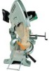
MODEL
C 15FB
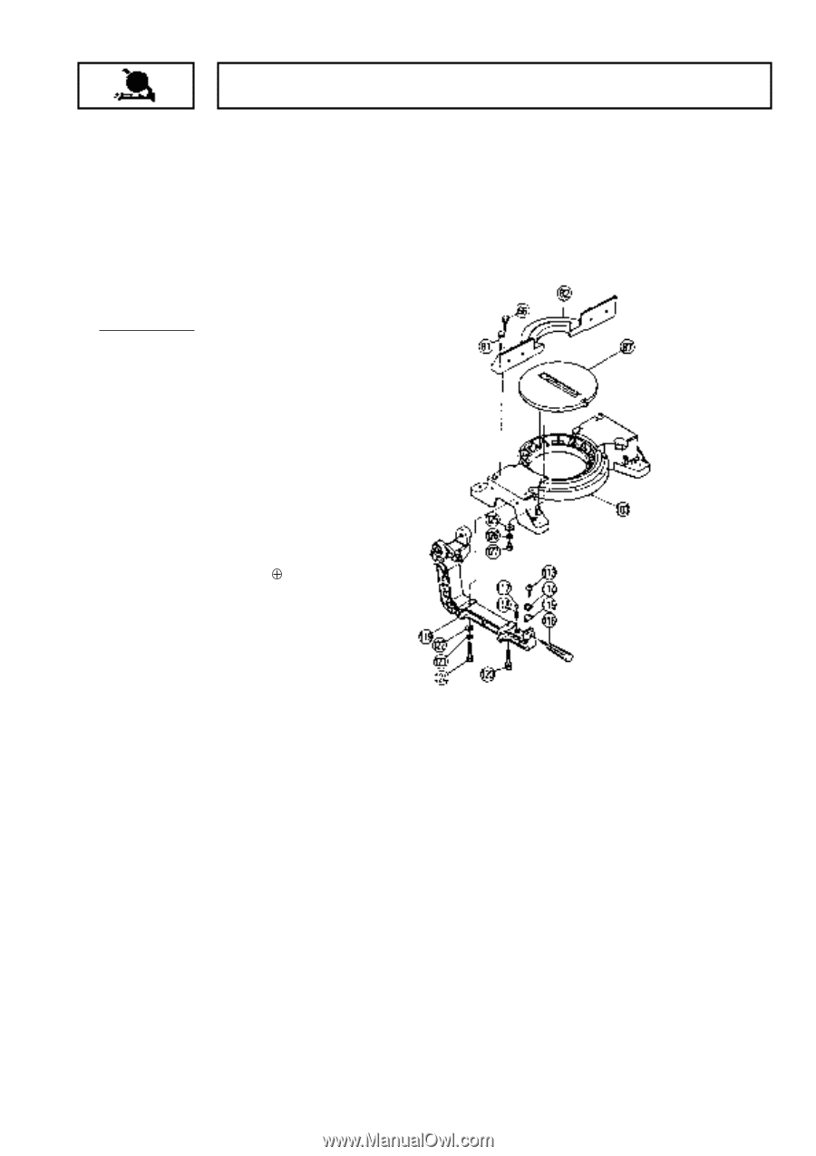
1. PRECAUTIONS IN DISASSEMBLY AND REASSEMBLY:
The circled numbers in the descriptions below correspond to the item numbers in the Parts List and exploded
assembly diagram.
[CAUTION]
Prior to commencing disassembly (including replacement of the saw blade), ensure that the
plug is disconnected from the power source.
1-1. Disassembly:
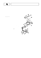
(1) Disassembly of the Base and Turn Table:
Tools Required:
•
17 mm Box Spanner
A. After removing the M10 x 65 Bolt
[120]
and
M10 x 65 Screw (G)
[124]
which fix the Hinge
[119]
, the Hinge
[119]
and upper portions
(Gear Case, etc.) can be separated from the
main body.
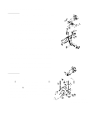
B. Remove the four M10 x 40 Bolts
[66]
which
fix Vise (B)
[82]
, and separate Vise (B)
[82]
from the Base Ass'y
[103]
.
C. Remove the two M6 x 16
-Hd. Machine
Screws
[127]
. The Turn Table
[87]
can then
be removed by pushing it up lightly from the
rear portion of the Base Ass'y
[103]
.
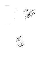
[NOTE]
When removing the Hinge
[119]
, be
very careful not to lose the D12.7 Steel
Ball
[117]
and Sprint (C)
[118]
.