Hunter 44660 Installation Guide
Hunter 44660 Manual
 |
View all Hunter 44660 manuals
Add to My Manuals
Save this manual to your list of manuals |
Hunter 44660 manual content summary:
- Hunter 44660 | Installation Guide - Page 1
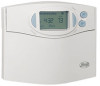
44660/44668 Programmable Thermostat Installation This easy installation guide will walk you through the proper installation of your Hunter® thermostat. For questions or assistance you may contact our technical department at 1-888-830-1326 (CAN 1-866-268-1936) . Hours of operation are 7 a.m. to 7 - Hunter 44660 | Installation Guide - Page 2
4 Jumper Wire Only RC, R O, Y/O, M W/B, W, W1 G, F Heat Valve (SSHP) Heat 24V Supply Jumper Cool 24V Supply Cool Contactor Heat Relay / Valve Fan Relay Wall Single Stage Heat Pump Wall 3 Wire Cool Only Wall 3 Wire Heat Only Wall 2 Wire Heat Only Wall 5 Wire Heat / Cool Wall 4 Wire Heat / Cool
-
 1
1 -
 2
2
 |
 |
44660/44668 PROGRAMMABLE
THERMOSTAT INSTALLATION
°is easy installation guide will walk you through the
proper installation of your Hunter® thermostat. For
questions or assistance you may contact our technical
department at 1-888-830-1326 (CAN 1-866-268-1936) .
Hours of operation are 7 a.m. to 7 p.m. Monday thru Friday
and 8 a.m. to 5 p.m. on Saturday.
°is thermostat is compatible with most oil, gas, electric,
2 wire hot water systems or single stage heats pumps. °is
thermostat will not control multi-stage heat pumps, line
voltage, or 3 wire hot water systems.
* Do not
disconnect the wires from your old thermostat
until all wires have been properly labeled.
You must
label all wiring accordingly
, wire color may not
indicate the function of the wire.
* Most thermostats are low voltage, and present no threat
to you during the uninstallation or installation process.
As a precaution though, turn off the power to your
Furnace by using the switch on the side or your breaker
box.
* °is thermostat is designed for use with 24 volt AC/
millivolt systems with a maximum of 1 amp
. Higher
amp or line voltage systems will cause damage to your
system and increase the risk of fire.
CAUTIONS /
WARNINGS
TOOLS
REMOVING THE OLD THERMOSTAT
Y
RC
G
W
Y
RC
G
W
Wallplate
°ermostat
°ermostat
Cover
Cover
Wallplate
Steps 1-1. - 1-2.
1-1. Turn off power to your furnace.
1-2. Remove the existing cover. Some thermostats may
have screws or other locking devices that must first
be removed. Once the wallplate is exposed, locate
the wire terminals. If the wire terminals are not visible,
they may be connected to the back of the wallplate.
Look for any additional screws, tabs, or locking devices
to remove the wallplate.
Warning: Do not remove any wires from the existing
thermostat until you have labeled all wires with the
included terminal stickers.
LABELING WIRES
OLD
THERMOSTAT
NEW
THERMOSTAT
W, W/b
W/B
Y, Y/O, Y1
Y/O
G, F
G
RH, R1
RH
RC, R
RC
O
O
Not Used
C
* Using the chart below, label the wires one at a time from
your old thermostat with the included terminal stickers
and remove them from the thermostat.
* To ensure wires do not fall back into the wall hole, you
may tape them to the wall, or wrap them around a pencil.
WIRE INSTALLATION
A jumper wire has been included on the mounting plate
between the RH and RC1 terminals. °is jumper should
remain between these 2 terminals unless RH and RC each
have their own wire.
Consult the diagram for "5 Wire Heat
/ Cool" on the back of this page.
3-1. Loosen but do not remove the screws on the terminal
block.
NOTE:
Ensure the ends of the wires have enough exposed
wire to insert into the terminal block.
3-2. Insert each wire into the appropriate terminal and
tighten the screw.
Note
. Consult the wiring charts under "Wiring Diagrams"
on the backside of this sheet to ensure proper wiring.
3-3. Gently pull each wire to ensure they are properly
secured.
INSTALLING THE MOUNTING PLATE
2-1. Separate the wallplate from the thermostat by
gripping the thermostat firmly on the top and bottom
with one hand. With the other hand, press the release
tab on the bottom of the thermostat. Pull firmly to
release the two parts from each other.
2-2. Position the wallplate on the wall and pull the wires
through the opening on the mounting plate.
2-3. Level the mounting plate for appearance.
2-4. Mark holes for plastic anchors provided by using a
pencil to place a mark on the wall if your existing holes
do not line up with those on the Hunter wallplate.
2-5. Remove the wall plate and drill two 3/16” holes where
marked.
Note:
Do not let the terminal stickers come loose while
removing the wallplate.
2-6. Tap the plastic anchors into the holes with a hammer
until they are flush with the wall.
2-7. Reposition the wall plate on the wall, pulling the wires
through the opening. Insert the mounting screws
through the wall plate and into the anchors. Verify
that the wall plate is visually level and securely tighten
both screws.
Step 2-7.
You may contact our Consumer Services department
at
1-888-830-1326 (CAN 1-866-268-1936)
or over the
Internet at
www.hunterfan.com/customer-care-center.
aspx/
for support or manuals. Hours of operation are 7
a.m. to 7 p.m. Monday thru Friday and 8 a.m. to 5 p.m. on
Saturday.
TECHNICAL SUPPORT
Steps 3-1. - 3-2.
FINISHING INSTALLATION
4-2. Once all the wiring and settings have been made on
the backplate and backside of the thermostat, place the
top of the thermostat at an angle over the two tabs on the
wall plate. Press the thermostat onto the wall plate and
press to snap the bottom tab into place.
Note
: Do not force the thermostat onto the wall plate, as
the terminal pins may be damaged. If the thermostat does
not snap into place properly, the unit may not work.
4-3. Insert two AA alkaline batteries.
4-4. Restore power at the electrical panel or furnace.
4-1. Locate the SW1 switch on the back of the thermostat.
If you have a gas/oil heating system, move this switch to
the HG (Heating Gas) position, electric based systems
should be set to HE (Heating Electric), and single stage
heat pumps (SSHP) should be set to SSHP.
SW1
Step 4-1.
Step 2-1.
W
G
Y
RH
RC
Steps 2-2. - 2-4.
©2009 Hunter Fan Company
43078-01
•
04/15/09
Warning:
Many 2 wire heat only systems are line voltage.
To determine this, check the size of the wire. If the wire
is much larger than the jumper wire included with this
thermostat do not connect to the thermostat.
Note:
If you have any addition wires that do not match
with the wiring diagrams in this manual, contact our
technical support department for assistance.
Warning:
Never connect a “common wire” to this
thermostat
, sometimes referred to as “C” or “B”. Doing
so could cause damage to the thermostat or your
heating/cooling system. Contact our technical support
department for wiring assistance.
Gather all tools necessary to complete your installation
before removing the old thermostat.
To install your thermostat you should have the following
tools:
Slotted Screwdriver
Phillips Screw Driver
Electric Drill and 3/16” drill bit
Hammer
Four 1.5v (AA) size alkaline batteries
Unpack your new Hunter® thermostat and ensure all
components are present in the Accessory Pack. °is
includes:
2 - #8 slotted screws
2 - wall anchors for mounting
1 - sheet of terminal labels
1 - jumper wire
1 - thermostat with mounting plate.
* Often, 2 wire heat only systems do not have terminal
labels. Connect 1 wire to the RH terminal and the other
to W.
* If both "O" and "B" are present, "B" may be a common
wire. Contact our technical support department for
wiring assistance.