IBM 7979CBU User Manual
IBM 7979CBU Manual
 |
View all IBM 7979CBU manuals
Add to My Manuals
Save this manual to your list of manuals |
IBM 7979CBU manual content summary:
- IBM 7979CBU | User Manual - Page 1
System x3650 Type 7979 User's Guide - IBM 7979CBU | User Manual - Page 2
- IBM 7979CBU | User Manual - Page 3
System x3650 Type 7979 User's Guide - IBM 7979CBU | User Manual - Page 4
, read the general information in "Notices," on page 115 and the Warranty and Support Information document on the IBM System x Documentation CD. Fifth Edition (December 2007) © Copyright International Business Machines Corporation 2007. All rights reserved. US Government Users Restricted Rights - IBM 7979CBU | User Manual - Page 5
1 Related documentation 2 Notices and statements in this document 3 Features and specifications 3 What your server offers 5 Reliability, availability, and serviceability features 7 IBM Director 8 The UpdateXpress program 9 Server controls, LEDs, and power 9 Front view 9 Rear view 11 - IBM 7979CBU | User Manual - Page 6
Online-spare memory 70 Removing a memory module 72 Installing the cables 82 Updating the server configuration 83 Chapter 3. Configuring the server 85 Using the Configuration/ Configuring the Gigabit Ethernet controllers 110 Updating IBM Director 111 Setting up a Remote Type 7979: User's Guide - IBM 7979CBU | User Manual - Page 7
European Union EMC Directive conformance statement 120 Taiwanese Class A warning statement 121 Chinese Class A warning statement 121 Japanese Voluntary Control Council for Interference (VCCI) statement 121 Korean Class A warning statement 121 Index 123 Contents v - IBM 7979CBU | User Manual - Page 8
vi System x3650 Type 7979: User's Guide - IBM 7979CBU | User Manual - Page 9
este produto, leia as Informações sobre Segurança. Antes de instalar este producto, lea la información de seguridad. Läs säkerhetsinformationen innan du installerar den här produkten. © Copyright IBM Corp. 2007 vii - IBM 7979CBU | User Manual - Page 10
power refers to ac power supplies only. If the server contains dc power supplies, see the documentation that comes with the dc power supplies. In a dc power environment, only trained service personnel other than IBM service technicians are authorized to connect or disconnect power to the - IBM 7979CBU | User Manual - Page 11
damage. v Disconnect the attached power cords, telecommunications systems, networks, and modems before you open the device covers, unless instructed otherwise in the installation and configuration procedures. v Connect and disconnect cables as described in the following table when installing, moving - IBM 7979CBU | User Manual - Page 12
Statement 2: CAUTION: When replacing the lithium battery, use only IBM Part Number 33F8354 or an equivalent type battery recommended by the manufacturer. If your system has a or disassemble Dispose of the battery as required by local ordinances or regulations. x System x3650 Type 7979: User's Guide - IBM 7979CBU | User Manual - Page 13
: v Do not remove the covers. Removing the covers of the laser product could result in exposure to hazardous laser radiation. There are no serviceable parts inside the device. v Use of controls or adjustments or performance of procedures other than those specified herein might result in hazardous - IBM 7979CBU | User Manual - Page 14
. To remove all electrical current from the device, ensure that all power cords are disconnected from the power source. 2 1 xii System x3650 Type 7979: User's Guide - IBM 7979CBU | User Manual - Page 15
, and energy levels are present inside any component that has this label attached. There are no serviceable parts inside these components. If you suspect a problem with one of these parts, contact a service technician. Statement 26: CAUTION: Do not place any object on top of rack-mounted devices - IBM 7979CBU | User Manual - Page 16
This server is suitable for use on an IT power-distribution system whose maximum phase-to-phase voltage is 240 V under any distribution fault condition. display workplace devices according to Clause 2 of the German Ordinance for Work with Visual Display Units. xiv System x3650 Type 7979: User's Guide - IBM 7979CBU | User Manual - Page 17
comes with a limited warranty. For information about the terms of the warranty and getting service and assistance, see the Warranty and Support Information document. The server contains IBM X-Architecture™ technologies, which help increase performance and reliability. For more information, see "What - IBM 7979CBU | User Manual - Page 18
your language in the Safety Information document. v Rack Installation Instructions This printed document contains instructions for installing the server in a rack. v Problem Determination and Service Guide This document is in PDF on the IBM System x Documentation CD. It contains information to help - IBM 7979CBU | User Manual - Page 19
is on the IBM System x Documentation problem situations. v Attention: These notices indicate potential damage to programs, devices, or data. An attention notice is placed just before the instruction the server. Depending on the server model computers will operate. Chapter 1. The System x3650 Type 7979 - IBM 7979CBU | User Manual - Page 20
list of supported microprocessors, see http://www.ibm.com/servers/eserver/ serverproven/compat/us/ Memory: v Twelve server) v One internal serial ATA (SATA) connector for tape v Support for Remote Supervisor Adapter II SlimLine Note: In messages and documentation, the term service 7979: User's Guide - IBM 7979CBU | User Manual - Page 21
module" on page 67. - Large system-memory capacity The server supports up to 48 GB of system memory. The memory controller supports up to 12 industry-standard, x4 or x8, PC2-5300 fully-buffered dual inline memory modules (FBD DIMMs). v IBM ServerGuide™ Setup and Installation CD The ServerGuide - IBM 7979CBU | User Manual - Page 22
Problem Determination and Service Guide. v Memory mirroring Memory mirroring improves the reliability of memory by writing information to the main memory an IBM Director extension that measures and reports server power if one of the fans fails. The server supports up to two 835-watt ac power supplies - IBM 7979CBU | User Manual - Page 23
computer design features are reliability, availability, and serviceability (RAS). The RAS features help to ensure the integrity of the data that is stored in the server, the availability of the server when you need it, and the ease with which you can diagnose and repair problems. The server - IBM 7979CBU | User Manual - Page 24
Upgradeable POST, BIOS, diagnostics, service processor microcode, and read-only memory (ROM) resident code, locally ibm.com/systems/management/director/resources/. It is updated every 6 to 8 weeks. v Support for IBM and non-IBM servers, desktop computers, workstations, and mobile computers. v Support - IBM 7979CBU | User Manual - Page 25
supported and installed device drivers and firmware in the server and installs available updates. You can download the UpdateXpress program from the Web at no additional cost, or you can purchase it on a CD. To download the program or purchase the CD, go to http://www.ibm.com/servers/ eserver - IBM 7979CBU | User Manual - Page 26
button: Press this button to turn the server on and off manually. v Power-on LED: When this LED is lit and not server, you must disconnect the power cord from the electrical outlet. Attention: In a dc power environment, only trained service personnel other than IBM service 7979: User's Guide - IBM 7979CBU | User Manual - Page 27
LEDs are lit. For any other combination of LEDs, see the Problem Determination and Service Guide on the IBM System x Documentation CD. Systems-management Ethernet connector: Use this connector to connect the server to a network for systems-management information control. This connector is active - IBM 7979CBU | User Manual - Page 28
LED: Use this LED to visually locate the server among other servers. You can use IBM Director to light this LED remotely. Power-on LED supports the Wake on LAN feature, the Wake on LAN feature can turn on the server. Note: When 4 GB or more of memory (physical or logical) is installed, some memory - IBM 7979CBU | User Manual - Page 29
server, you must disconnect it from the power source. Attention: In a dc power environment, only trained service personnel other than IBM service shutdown of the operating system and turn off the server, if your operating system supports this feature. v If the operating system stops functioning - IBM 7979CBU | User Manual - Page 30
14 System x3650 Type 7979: User's Guide - IBM 7979CBU | User Manual - Page 31
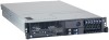
chapter provides detailed instructions for installing optional hardware devices in the server. Server components The following illustrations show the major components in the server. The illustrations Power backplane 2.5-inch drive cage with hard disk drive backplane © Copyright IBM Corp. 2007 15 - IBM 7979CBU | User Manual - Page 32
Low-profile adapter Remote Supervisor Adapter II SlimLine Heat-sink filler Heat sink Microprocessor VRM Heat-sink retention module Riser-card assembly Full-height adapter DIMM air baffle DIMM ServeRAID SAS controller System board 16 System x3650 Type 7979: User's Guide - IBM 7979CBU | User Manual - Page 33
System-board optional-device connectors The following illustration shows the connectors on the system board for user-installable optional devices. PCI Express slot 4 connector PCI Express slot 3 connector Remote Supervisor Adapter II SlimLine connector PCI riser card connector ServeRAID SAS - IBM 7979CBU | User Manual - Page 34
connectors on the power-backplane board. System-board connector Fan 10 connector Hard disk drive power connector Fan 7 connector 18 System x3650 Type 7979: User's Guide - IBM 7979CBU | User Manual - Page 35
System-board internal cable connectors The following illustration shows the internal connectors on the system board. IPMB connector SATA tape drive signal (J102) Hard disk drive backplane signal (J92) Operator panel (J50) CD/DVD power (J12) CD/DVD signal (J37) Power backplane (J72) Tape drive - IBM 7979CBU | User Manual - Page 36
System-board external connectors The following illustration shows the external input/output connectors on the system board. USB 1 USB 2 Ethernet 2 / USB 3 Ethernet 1 / USB 4 Video Serial Systems-management Ethernet SAS 20 System x3650 Type 7979: User's Guide - IBM 7979CBU | User Manual - Page 37
in the illustration are reserved. See the section about recovering the basic input/output system (BIOS) code in the Problem Determination and Service Guide on the IBM System x Documentation CD for information about using the boot block recovery jumper. SAS controller jumper Reserved (J89) Boot block - IBM 7979CBU | User Manual - Page 38
devices" on page 30, and "Turning off the server" on page 13.) Attention: In a dc power environment, only trained service personnel other than IBM service technicians are authorized to connect or disconnect power to in this document are reserved. 22 System x3650 Type 7979: User's Guide - IBM 7979CBU | User Manual - Page 39
System-board LEDs The following illustration shows the light-emitting diodes (LEDs) on the system board. Riser-card-missing error LED 3 v battery error LED Remote Supervisor Adapter II SlimLine error LED PCI slot 3 error LED PCI slot 4 error LED Microprocessor 1 error LED Microprocessor 2 error LED - IBM 7979CBU | User Manual - Page 40
Riser-card assembly LEDs The following illustration shows the light-emitting diodes (LEDs) on the riser-card assembly. PCI Slot 2 error LED PCI Slot 1 error LED 24 System x3650 Type 7979: User's Guide - IBM 7979CBU | User Manual - Page 41
Problem Determination and Service Guide on the IBM SPEC The power supplies are using more power than their maximum rating. 1. Remove optional devices from the server. 2. Replace the failing power supply. Attention: In a dc power environment, only trained service personnel other than IBM service - IBM 7979CBU | User Manual - Page 42
problem is solved. v See the parts listing in the Problem Determination and Service Guide dc power environment, only trained service personnel other than IBM service technicians are authorized to connect or components that are indicated. MEM A memory error has occurred. Replace the failing DIMM - IBM 7979CBU | User Manual - Page 43
the suggested actions in the order in which they are listed in the Action column until the problem is solved. v See the parts listing in the Problem Determination and Service Guide to determine which components are customer replaceable units (CRU) and which components are field replaceable units - IBM 7979CBU | User Manual - Page 44
server, complete the following steps: 1. Go to http://www.ibm.com/systems/support/. 2. Under Product support server is otherwise working correctly. If the server is not working correctly, see "Solving problems" in the Installation Guide on the IBM service personnel other than IBM service technicians - IBM 7979CBU | User Manual - Page 45
to halt, which could result in the loss of data. To avoid this potential problem, always use an electrostatic-discharge wrist strap or other grounding system when working inside the server with the power on. The server supports hot-plug, hot-add, and hot-swap devices and is designed to operate - IBM 7979CBU | User Manual - Page 46
server as you lean over it. server. Handling static-sensitive devices Attention: Static electricity can damage the server working inside the server with the power on on the outside of the server for at least 2 it directly into the server without setting down the device on the server cover or on - IBM 7979CBU | User Manual - Page 47
error code is displayed, indicating that an operating system was not found but the server is otherwise working correctly. If the server is not working correctly, see the Problem Determination and Service Guide for diagnostic information. To remove the cover, complete the following steps: 1. Read the - IBM 7979CBU | User Manual - Page 48
. The PCI-X connectors support single-width IXA adapters. See http://www.ibm.com/ servers/eserver/serverproven/compat/us/ server and peripheral devices, and disconnect the power cord and all external cables. Attention: In a dc power environment, only trained service personnel other than IBM service - IBM 7979CBU | User Manual - Page 49
server and all peripheral devices are turned off and that the power cords and all external cables are disconnected. Attention: In a dc power environment, only trained service personnel other than IBM service the release tab posts, the guides on the rear of the server, and the riser-card connector - IBM 7979CBU | User Manual - Page 50
(see "Turning off the server" on page 13). Attention: In a dc power environment, only trained service personnel other than IBM service technicians are authorized to connect or the air baffle out of the server. Attention: For proper cooling and airflow, replace the air baffle before you turn on the - IBM 7979CBU | User Manual - Page 51
and peripheral devices are turned off (see "Turning off the server" on page 13) and that all power cords and external cables are disconnected. Attention: In a dc power environment, only trained service personnel other than IBM service technicians are authorized to connect or disconnect power to the - IBM 7979CBU | User Manual - Page 52
(see "Turning off the server" on page 13). Attention: In a dc power environment, only trained service personnel other than IBM service technicians are authorized to connect or the air baffle out of the server. Attention: For proper cooling and airflow, replace the air baffle before you turn on the - IBM 7979CBU | User Manual - Page 53
and peripheral devices are turned off (see "Turning off the server" on page 13) and that all power cords and external cables are disconnected. Attention: In a dc power environment, only trained service personnel other than IBM service technicians are authorized to connect or disconnect power to the - IBM 7979CBU | User Manual - Page 54
Supervisor Adapter II SlimLine, see "Installing a Remote Supervisor Adapter II SlimLine" on page 43. v The server supports only 3.3 V and universal PCI adapters. v The PCI bus configuration is as follows: - Non-hot-plug length PCI Express x8 (x8 lanes), slot 1 38 System x3650 Type 7979: User's Guide - IBM 7979CBU | User Manual - Page 55
2 are non-hot-plug, 64-bit, 133-MHz PCI-X slots, which support Integrated xSeries Adapter (IXA) single-width adapters. v The system scans devices in off the server" on page 13). Attention: In a dc power environment, only trained service personnel other than IBM service technicians are authorized - IBM 7979CBU | User Manual - Page 56
assembly 8. If you removed the PCI riser-card assembly to install the adapter, align the riser-card assembly with the release-tab posts, rear guides, and connector; then, press the PCI riser-card assembly firmly into the connector (see "Installing the riser-card assembly" on page 33). 40 System - IBM 7979CBU | User Manual - Page 57
Access holes Guide Release tabs Guide 9. Connect any required cables to the adapter. Attention: components under the PCI riser-card assembly. v Make sure that cables are not pinched by the server components. 10. Perform any configuration tasks that are required for the adapter. If you have other - IBM 7979CBU | User Manual - Page 58
and peripheral devices and disconnect all power cords and external cables (see "Turning off the server" on page 13). Attention: In a dc power environment, only trained service personnel other than IBM service technicians are authorized to connect or disconnect power to the dc power supply. See the - IBM 7979CBU | User Manual - Page 59
Ethernet port on the rear of the server is active. Note: Earlier versions of the Remote Supervisor Adapter II SlimLine might not work in this server. See http://www.ibm.com/servers/eserver/serverproven/compat/us/ for the supported Remote Supervisor Adapter II SlimLine. Chapter 2. Installing - IBM 7979CBU | User Manual - Page 60
and external cables (see "Turning off the server" on page 13). Attention: In a dc power environment, only trained service personnel other than IBM service technicians are authorized to connect or disconnect power to "Completing the installation" on page 81. 44 System x3650 Type 7979: User's Guide - IBM 7979CBU | User Manual - Page 61
and peripheral devices and disconnect all power cords and external cables (see "Turning off the server" on page 13). Attention: In a dc power environment, only trained service personnel other than IBM service technicians are authorized to connect or disconnect power to the dc power supply. See the - IBM 7979CBU | User Manual - Page 62
in a dedicated slot on the system board. The server comes with a ServeRAID-8k-l SAS Controller installed. server" on page 13). Attention: In a dc power environment, only trained service personnel other than IBM service to any unpainted metal surface on the server. Then, remove the ServeRAID-8k SAS - IBM 7979CBU | User Manual - Page 63
disk drive and follow those instructions in addition to the instructions in this chapter. Important: Do not install a SCSI hard disk drive in this server; install only SAS hard disk drives. The following notes describe the type of hard disk drive that the server supports and other information that - IBM 7979CBU | User Manual - Page 64
supported 2.5-inch hard disk drives, see http://www.ibm.com/servers/eserver/ serverproven/compat/us/. v All hot-swap drives in the server is printed on the front of the server. The following illustrations show how to system cooling, do not operate the server for more than 10 minutes without either - IBM 7979CBU | User Manual - Page 65
server. 3. Install the hard disk drive in the hot-swap bay: a. Make sure that the tray handle is open (that is, perpendicular to the drive). b. Align the drive assembly with the guide disk drives. See the RAID documentation on the IBM ServeRAID Support CD for information about RAID controllers. If - IBM 7979CBU | User Manual - Page 66
. See the RAID documentation on the IBM ServeRAID Support CD for information about RAID controllers. instructions that come with the drive, setting any switches or jumpers; then, see "Installing a SATA tape drive in a 3.5-inch model server" or "Installing a SATA tape drive in a 2.5-inch model server - IBM 7979CBU | User Manual - Page 67
and "Installation guidelines" on page 28. 2. Turn off the server and peripheral devices, and disconnect the power cords and all external cables. Attention: In a dc power environment, only trained service personnel other than IBM service technicians are authorized to connect or disconnect power to - IBM 7979CBU | User Manual - Page 68
SATA tape drive signal connector SATA tape cable 12. Install the fan-bracket assembly. If you have other optional devices to install or remove, do so now. Otherwise, go to "Completing the installation" on page 81. 52 System x3650 Type 7979: User's Guide - IBM 7979CBU | User Manual - Page 69
and "Installation guidelines" on page 28. 2. Turn off the server and peripheral devices, and disconnect the power cords and all external cables. Attention: In a dc power environment, only trained service personnel other than IBM service technicians are authorized to connect or disconnect power to - IBM 7979CBU | User Manual - Page 70
installation" on page 81. Installing a SCSI tape drive in a 3.5-inch model server Use these procedures to install a supported SCSI tape drive, such as the IBM DDS Generation 5 Internal Tape Drive, and to connect the tape drive to a supported SCSI adapter in PCI slot 1 of the riser-card assembly. See - IBM 7979CBU | User Manual - Page 71
and "Installation guidelines" on page 28. 2. Turn off the server and peripheral devices, and disconnect the power cords and all external cables. Attention: In a dc power environment, only trained service personnel other than IBM service technicians are authorized to connect or disconnect power to - IBM 7979CBU | User Manual - Page 72
disk drive cage and out the front of the server. Note: The terminator on the short section into the bays, gently pulling the cables farther into the server as you do so, until the tape-drive assembly stops 14. Route the SCSI signal cable to the supported SCSI adapter that is installed in slot 1 of - IBM 7979CBU | User Manual - Page 73
SCSI signal cable Cable clamp 15. Connect the tape-drive power cable to the tape-drive power connector, J100 (see "System-board internal cable connectors" on page 19 for the location of the power connector). 16. Replace the hard disk drive backplane signal cable, making sure that it passes through - IBM 7979CBU | User Manual - Page 74
installation" on page 81. Installing a SCSI tape drive in a 2.5-inch model server Use these procedures to install a supported SCSI tape drive, such as the IBM DDS Generation 5 Internal Tape Drive, and to connect the tape drive to a supported SCSI adapter in PCI slot 1 of the riser-card assembly. See - IBM 7979CBU | User Manual - Page 75
and "Installation guidelines" on page 28. 2. Turn off the server and peripheral devices, and disconnect the power cords and all external cables. Attention: In a dc power environment, only trained service personnel other than IBM service technicians are authorized to connect or disconnect power to - IBM 7979CBU | User Manual - Page 76
page 19 for the location of the connector and cable clamp. 18. Route the SCSI signal cable to the supported SCSI adapter that is installed in slot 1 of the riser-card assembly, as shown in the following illustration. Make to the connector on the system board. 60 System x3650 Type 7979: User's Guide - IBM 7979CBU | User Manual - Page 77
and "Installation guidelines" on page 28. 2. Turn off the server and peripheral devices, and disconnect the power cords and all external cables. Attention: In a dc power environment, only trained service personnel other than IBM service technicians are authorized to connect or disconnect power to - IBM 7979CBU | User Manual - Page 78
server model); then, disconnect the SCSI signal cable from the SCSI adapter and remove the cable from the server assembly from the server. d. Disconnect server, gently pull the server server; then, lift the cable out of the server ibm.com/servers/eserver/serverproven/compat/us/ for a list of supported - IBM 7979CBU | User Manual - Page 79
updates for your server, complete the following steps: 1. Go to http://www.ibm.com/systems/support/. 2. Under Product support, click System server; therefore, you do not have to set any microprocessor frequency-selection jumpers or switches. v If you have to replace a microprocessor, call for service - IBM 7979CBU | User Manual - Page 80
and disconnect all power cords and external cables (see "Turning off the server" on page 13). Attention: In a dc power environment, only trained service personnel other than IBM service technicians are authorized to connect or disconnect power to the dc power supply. See the documentation that - IBM 7979CBU | User Manual - Page 81
VRM in the VRM connector. Alignment key a. Touch the static-protective package containing the VRM to any unpainted metal surface on the outside of the server. Then, remove the VRM from the package. b. Turn the VRM so that the keys align correctly with the VRM connector. c. Firmly press the VRM - IBM 7979CBU | User Manual - Page 82
the bottom of the heat sink. c. Align the heat sink above the microprocessor with the thermal-grease side down. 66 System x3650 Type 7979: User's Guide - IBM 7979CBU | User Manual - Page 83
that you must consider when installing DIMMs: v The server supports up to 12 Fully Buffered DIMM PC2-5300 512 MB, 1 GB, 2 GB, and 4 GB DIMMs, for a maximum of 48 GB of system memory. See http://www.ibm.com/servers/eserver/serverproven/compat/us/ for a list of memory modules that you can use with the - IBM 7979CBU | User Manual - Page 84
the active pair to the mirroring pair. See "Memory mirroring" on page 69 for more information about memory mirroring and the DIMM installation sequence that is required. v The server supports online-spare memory. This feature disables the failed memory from the system configuration and activates an - IBM 7979CBU | User Manual - Page 85
server and peripheral devices, and disconnect the power cord and all external cables. Attention: In a dc power environment, only trained service personnel other than IBM service " on page 81. Memory mirroring You can configure the server to use memory mirroring. Memory mirroring stores data in two - IBM 7979CBU | User Manual - Page 86
3 3, 6 Mirroring DIMMs 7, 10 8, 11 9, 12 Online-spare memory The server supports online-spare memory. This feature disables the failed memory from the system configuration and activates an online-spare pair of DIMMs to in Table 7 on page 71, instead. 70 System x3650 Type 7979: User's Guide - IBM 7979CBU | User Manual - Page 87
In the configuration that you use, install the largest DIMMs first. Table 6. Online-spare DIMM configurations, basic scheme Number of DIMMs DIMM connectors Results 4 1 and 4 (largest DIMMs) 2 and 5 Online-sparing on branch 0 6 1 and 4 (largest DIMMs) 2 and 5 3 and 6 8 1 and 4 (largest - IBM 7979CBU | User Manual - Page 88
dc power supplies. In a dc power environment, only trained service personnel other than IBM service technicians are authorized to connect or disconnect power to the dc power supply and to install and remove a dc power supply. The server supports a maximum of two hot-swap ac power supplies. Important - IBM 7979CBU | User Manual - Page 89
, only trained service personnel other than IBM service technicians are authorized to connect or disconnect power to the dc power supply and to install and remove a dc power supply. See the documentation that comes with each dc power supply for installation instructions. Chapter 2. Installing - IBM 7979CBU | User Manual - Page 90
other than IBM service technicians are authorized to connect or disconnect power to the dc power supply. See the documentation that comes with each dc power supply for installation instructions. The following illustration shows the ac power-supply connectors on the back of the server. Power cord - IBM 7979CBU | User Manual - Page 91
: In a dc power environment, only trained service personnel other than IBM service technicians are authorized to connect or disconnect power to the dc power supply. See the documentation that comes with each dc power supply for removal instructions. 3. Grasp the power-supply handle. 4. Press - IBM 7979CBU | User Manual - Page 92
2. If you have not done so already, slide the server out of the rack and remove the cover (see "Removing the fan is toward the left side of the server. 4. Push the new fan into the fan Removing a fan The server comes with up to 10 replaceable fans. Attention: To ensure proper server operation, if a - IBM 7979CBU | User Manual - Page 93
on page vii and "Installation guidelines" on page 28. 2. Slide the server out of the rack and remove the cover (see "Removing the cover" on failing fan. 4. Pull the handles toward each other and lift the fan out of the server. 5. Replace the fan as soon as possible (see "Installing a fan" on page 75 - IBM 7979CBU | User Manual - Page 94
the server and peripheral devices, and disconnect the power cords and all external cables. Attention: In a dc power environment, only trained service personnel other than IBM service technicians are levers and lift the fan-bracket assembly out of the server. 78 System x3650 Type 7979: User's Guide - IBM 7979CBU | User Manual - Page 95
on page 28. 2. Make sure that the server and all peripheral devices are turned off and that the power cords and all external cables are disconnected. Attention: In a dc power environment, only trained service personnel other than IBM service technicians are authorized to connect or disconnect power - IBM 7979CBU | User Manual - Page 96
server and peripheral devices, and disconnect the power cords and all external cables. Attention: In a dc power environment, only trained service personnel other than IBM service server. Drive retention clip Alignment pins 5. From the front of the server sure that the server and peripheral devices - IBM 7979CBU | User Manual - Page 97
service personnel other than IBM service technicians are authorized to connect or disconnect power to the dc power supply. See the documentation that comes with each dc power supply. 3. Remove the cover (see "Removing the cover" on page 31). 4. Follow the instructions removed the server cover, place - IBM 7979CBU | User Manual - Page 98
: In a dc power environment, only trained service personnel other than IBM service technicians are authorized to connect or disconnect power to the matching slots in the server chassis. 3. Press down on the cover-release latch to lock the cover in place. 4. Slide the server into the rack. Connecting - IBM 7979CBU | User Manual - Page 99
, only trained service personnel other than IBM service technicians are authorized to connect or disconnect power to the dc power supply. See the documentation that comes with each dc power supply for instructions and an illustration of the dc power supply. You must turn off the server before you - IBM 7979CBU | User Manual - Page 100
If you have installed a Remote Supervisor Adapter II SlimLine to manage the server remotely, see the Remote Supervisor Adapter User's Guide, which comes with the adapter, for information about setting up, configuring, and using the adapter. For information about configuring the integrated Gigabit - IBM 7979CBU | User Manual - Page 101
can use to centrally manage System x and xSeries servers. If you plan to use IBM Director to manage the server, you must check for the latest applicable IBM Director updates and interim fixes. For information about updating IBM Director, see "Updating IBM Director" on page 111. For more information - IBM 7979CBU | User Manual - Page 102
, a USB device summary, and the amount of installed memory. When you make configuration changes through other options in the Product Data Select this choice to view the machine type and model of the server, the serial number, the system UUID, the system board identifier, the revision User's Guide - IBM 7979CBU | User Manual - Page 103
server checks devices to find a boot record. The server starts from the first boot record that it finds. If the server has Wake on LAN hardware and software and the operating system supports : The server might malfunction if these options are incorrectly configured. Follow the instructions on the - IBM 7979CBU | User Manual - Page 104
all microprocessors in the server. Virtualization Technology enables in the Problem Determination and Service Guide on the IBM System x Documentation that are connected to the slot. Follow the instructions on the screen to page forward or backward to use to provide USB support for remote access to - IBM 7979CBU | User Manual - Page 105
log contains all event and error messages that have been generated during POST, by the system management interface handler, and by the system service processor. Run the diagnostic programs to get more information about error codes that occur. See the Problem Chapter 3. Configuring the server 89 - IBM 7979CBU | User Manual - Page 106
Passwords Determination and Service Guide on the IBM System x Documentation CD for instructions for running the diagnostic programs. -on password If a power-on (user) password is set, when you turn on the server, the system startup will not be completed until you type the power-on password. You can - IBM 7979CBU | User Manual - Page 107
v Remove the battery from the server and then reinstall it. For instructions for removing the battery, see the Problem Determination and Service Guide on the IBM System x Documentation CD. v Change the position of the clear CMOS jumper on the system board to bypass the power-on password check. See " - IBM 7979CBU | User Manual - Page 108
for instructions. 5. Move the clear-CMOS switch (switch 1 on SW2) to the On position. 6. Install the cover and connect the server to a keyboard, monitor, and mouse; then, connect the server to a power source. Attention: In a dc power environment, only trained service personnel other than IBM service - IBM 7979CBU | User Manual - Page 109
; then, turn on the server. Attention: In a dc power environment, only trained service personnel other than IBM service technicians are authorized to connect . Not all features are supported on all server models. The ServerGuide program requires a supported IBM server with an enabled startable ( - IBM 7979CBU | User Manual - Page 110
free installation for supported Windows operating supported IBM server model. The setup program provides a list of tasks that are required to set up your server model. On a server information about the server model, service processor, hard disk system CD and restart the server. At this point, the - IBM 7979CBU | User Manual - Page 111
ServerGuide If you have already configured the server hardware and you are not using the ServerGuide program to install your operating system, complete the following steps to download the latest operating-system installation instructions from the IBM Web site. Note: Changes are made periodically - IBM 7979CBU | User Manual - Page 112
instructions on the screen carefully before making a selection. Configuring the controller To configure a RAID array on the server, complete the following steps: 1. Turn on the server. 2. When the message Press for IBM Manager, which is on the IBM ServeRAID Support CD, to perform the Guide - IBM 7979CBU | User Manual - Page 113
instructions for using ServeRAID Manager to configure the SAS and RAID controllers, see the ServeRAID documentation on the IBM ServeRAID Support Startable CD mode. To run ServeRAID Manager in Startable CD mode, turn on the server; then, insert the CD into the CD-RW/DVD drive. If ServeRAID Manager - IBM 7979CBU | User Manual - Page 114
provides basic service-processor environmental monitoring functions for the server. If an problem and also records the error in the BMC system event log. The baseboard management controller also provides the following remote server .ibm.com/ systems/support/ 98 System x3650 Type 7979: User's Guide - IBM 7979CBU | User Manual - Page 115
the BMC firmware from http://www.ibm.com/ systems/support/ b. Update the BMC firmware, following the instructions that come with the update file selected; then, press Enter. Linux configuration For SOL operation on the server, you must configure the Linux® operating system to expose the Linux - IBM 7979CBU | User Manual - Page 116
examples show the original content of the /etc/lilo.conf file and the content of this file after modification. 100 System x3650 Type 7979: User's Guide - IBM 7979CBU | User Manual - Page 117
read-only root=/dev/hda6 image=/boot/vmlinuz-2.4.9-e.12 label=linux-up initrd=/boot/initrd-2.4.9-e.12.img read-only root=/dev/hda6 Chapter 3. Configuring the server 101 - IBM 7979CBU | User Manual - Page 118
SOL title Red Hat Linux (2.4.9-e.12smp) SOL Interactive root (hd0,0) kernel /vmlinuz-2.4.9-e.12smp ro root=/dev/hda6 console=tty1 102 System x3650 Type 7979: User's Guide - IBM 7979CBU | User Manual - Page 119
.img title Red Hat Enterprise Linux ES-up (2.4.9-e.12) root (hd0,0) kernel /vmlinuz-2.4.9-e.12 ro root=/dev/hda6 initrd /initrd-2.4.9-e.12.img Chapter 3. Configuring the server 103 - IBM 7979CBU | User Manual - Page 120
SUSE SLES 9.0 configuration: Note: This procedure is based on a default installation of SUSE Linux Enterprise Server (SLES) 9.0. The file names, structures, and commands might be different for other versions of SUSE Modify the /boot/grub/menu.lst file: 104 System x3650 Type 7979: User's Guide - IBM 7979CBU | User Manual - Page 121
kernel (hd0,1)/boot/vmlinuz root=/dev/hda2 acpi=oldboot vga=791 console=tty1 console=ttyS0,19200 initrd (hd0,1)/boot/initrd title floppy Chapter 3. Configuring the server 105 - IBM 7979CBU | User Manual - Page 122
a. Type bootcfg at a Windows command prompt; then, press Enter to display the current boot options for your server. b. Verify the following changes to the bootcfg settings: v In the Boot Loader Settings section, make sure that the output after modification. 106 System x3650 Type 7979: User's Guide - IBM 7979CBU | User Manual - Page 123
utility program, install and load the program before problems occur. To install the OSA SMBridge management utility program on a server running a Windows operating system, complete the following steps: 1. Go to http://www.ibm.com/systems/support/ and download the utility program and create the - IBM 7979CBU | User Manual - Page 124
will be accepted by the utility program. To accept connections from any server, type INADDR_ANY as the IP address. Also specify the port number user to perform these procedures. 1. Go to http://www.ibm.com/systems/support/. Download the utility program and create the OSA BMC Management Utility Guide - IBM 7979CBU | User Manual - Page 125
the following steps: 1. Insert the configuration utility diskette into the diskette drive and restart the server. 2. From a command-line prompt, type bmc_cfg and press Enter. 3. Follow the instructions on the screen. Using the baseboard management controller firmware update utility program Use the - IBM 7979CBU | User Manual - Page 126
Display system information that is related to the server and the globally unique identifier (GUID). Configuring the Gigabit Ethernet controllers The Ethernet of data on the network. If the Ethernet ports in the server support auto-negotiation, the controllers detect the data-transfer rate (10BASE-T, - IBM 7979CBU | User Manual - Page 127
comes with the server, follow the instructions on the Web page to download the latest version. 2. Install IBM Director. 3. Download and install any applicable updates or interim fixes for the server: a. Go to http://www.ibm.com/systems/support/. b. Under Product support, click System x. c. Under - IBM 7979CBU | User Manual - Page 128
ibm.com/systems/support/. Cabling the Remote Supervisor Adapter II SlimLine You can manage the server server. For additional information about network configuration, see the Remote Supervisor Adapter II Installation Guide SlimLine firmware update v Integrated service processor firmware update v Video - IBM 7979CBU | User Manual - Page 129
, to install the software and firmware. 8. Restart the server after the software and firmware are installed. Completing the setup See the IBM Remote Supervisor Adapter II User's Guide on the IBM System x Documentation CD for instructions for completing the configuration, including the following - IBM 7979CBU | User Manual - Page 130
114 System x3650 Type 7979: User's Guide - IBM 7979CBU | User Manual - Page 131
responsibility to evaluate and verify the operation of any non-IBM product, program, or service. IBM may have patents or pending patent applications covering subject matter countries, or both: Active Memory Active PCI Active PCI-X AIX Alert on LAN IBM IBM (logo) IntelliStation NetBAY Netfinity - IBM 7979CBU | User Manual - Page 132
other countries. Other company, product, or service names may be trademarks or service marks of others. Important notes Processor speed largest currently supported drives that are available from IBM. Maximum memory might require replacement of the standard memory with an optional memory module. - IBM 7979CBU | User Manual - Page 133
representations or warranties with respect to non-IBM products. Support (if any) for the non-IBM products is provided by the third party, not IBM. Some software might differ from its retail version (if available) and might not include user manuals or all program functionality. Product recycling and - IBM 7979CBU | User Manual - Page 134
proper collection and treatment, contact your local IBM representative. Battery return program This product may contain a sealed lead acid, nickel cadmium, nickel metal hydride, lithium, or lithium ion battery. Consult your user manual or service manual for specific battery information. The battery - IBM 7979CBU | User Manual - Page 135
of hazardous substances. For proper collection and treatment, contact your local IBM representative. For California: Perchlorate material - special handling may apply. if not installed and used in accordance with the instruction manual, may cause harmful interference to radio Appendix. Notices 119 - IBM 7979CBU | User Manual - Page 136
in order to meet FCC emission limits. IBM is not responsible for any radio or relating to electromagnetic compatibility. IBM cannot accept responsibility for any including the fitting of non-IBM option cards. This product has Community contact: IBM Technical Regulations Pascalstr. 100, Stuttgart, Germany - IBM 7979CBU | User Manual - Page 137
Telephone: 0049 (0)711 785 1176 Fax: 0049 (0)711 785 1283 E-mail: [email protected] Taiwanese Class A warning statement Chinese Class A warning statement Japanese Voluntary Control Council for Interference (VCCI) statement Korean Class A warning statement Appendix. Notices 121 - IBM 7979CBU | User Manual - Page 138
122 System x3650 Type 7979: User's Guide - IBM 7979CBU | User Manual - Page 139
A ac power LED 11 acoustical noise emissions 4 Active Memory 5 adapter installing 38 PCI bus, identification 38 PCI Express sel 110 sysinfo 110 © Copyright IBM Corp. 2007 command-line interface (continued) for remote management 109 components, server 15 configuration Configuration/Setup Utility 86 - IBM 7979CBU | User Manual - Page 140
SlimLine 43 tape drive 50 VRM 65 124 System x3650 Type 7979: User's Guide J jumper, clear CMOS (password override) 91 jumpers 21 L LEDs 11 Ethernet activity 11 Ethernet-link status 11 front of server 9 rear of server 11 riser-card assembly 24 system board 23 light path diagnostics about 6 location - IBM 7979CBU | User Manual - Page 141
93 NOS installation 94 setup 94 using 93 ServerGuide CD 5 service processor, defined 12 setting clear CMOS (password override) jumper 91 thermal material, heat sink 66 trademarks 115 turning off the server 13 turning on the server 12 U United States electronic emission Class A notice 119 United - IBM 7979CBU | User Manual - Page 142
user password See power-on password using baseboard management controller utility programs 109 utility program Configuration/Setup 86 IBM ServeRAID Configuration 95 V video connector front 10 rear 12 voltage regulator module, installing 65 VRM See voltage regulator module W weight 4 126 System x3650 - IBM 7979CBU | User Manual - Page 143
- IBM 7979CBU | User Manual - Page 144
Part Number: 44R5189 Printed in USA (1P) P/N: 44R5189
-
 1
1 -
 2
2 -
 3
3 -
 4
4 -
 5
5 -
 6
6 -
 7
7 -
8
-
9
-
10
-
11
-
12
-
13
-
14
-
15
-
16
-
17
-
18
-
19
-
20
-
21
-
22
-
23
-
24
-
25
-
26
-
27
-
28
-
29
-
30
-
31
-
32
-
33
-
34
-
35
-
36
-
37
-
38
-
39
-
40
-
41
-
42
-
43
-
44
-
45
-
46
-
47
-
48
-
49
-
50
-
51
-
52
-
53
-
54
-
55
-
56
-
57
-
58
-
59
-
60
-
61
-
62
-
63
-
64
-
65
-
66
-
67
-
68
-
69
-
70
-
71
-
72
-
73
-
74
-
75
-
76
-
77
-
78
-
79
-
80
-
81
-
82
-
83
-
84
-
85
-
86
-
87
-
88
-
89
-
90
-
91
-
92
-
93
-
94
-
95
-
96
-
97
-
98
-
99
-
100
-
101
-
102
-
103
-
104
-
105
-
106
-
107
-
108
-
109
-
110
-
111
-
112
-
113
-
114
-
115
-
116
-
117
-
118
-
119
-
120
-
121
-
122
-
123
-
124
-
125
-
126
-
127
-
128
-
129
-
130
-
131
-
132
-
133
-
134
-
135
-
136
-
137
-
138
-
139
-
140
-
141
-
142
-
143
-
144
 |
 |

System
x3650
Type
7979
User’s
Guide
±²³