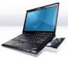
IBM R500 Hardware Maintenance Manual
IBM R500 - LENOVO ThinkPad - Genuine Windows 7 Home Premium Manual
 |
UPC - 074450008671
View all IBM R500 manuals
Add to My Manuals
Save this manual to your list of manuals |
IBM R500 manual content summary:
- IBM R500 | Hardware Maintenance Manual - Page 1
ThinkPad R500 Hardware Maintenance Manual - IBM R500 | Hardware Maintenance Manual - Page 2
- IBM R500 | Hardware Maintenance Manual - Page 3
ThinkPad R500 Hardware Maintenance Manual - IBM R500 | Hardware Maintenance Manual - Page 4
Before using this information and the product it supports, be sure to read the general information under "Notices" on page 215. Third Edition (September 2009) © Copyright Lenovo 2008, 2009. LENOVO products, data, computer software, and services have been developed exclusively at private expense and - IBM R500 | Hardware Maintenance Manual - Page 5
rest or palm rest with fingerprint reader 88 1050 DIMM 91 1060 Keyboard 92 1070 PCI Express Mini Card for wireless LAN . . . 94 1080 Intel Turbo Memory Minicard 98 1090 Backup battery 99 1100 Keyboard bezel and speakers 100 1110 Fan assembly 103 1120 CPU 107 1130 LCD assembly 108 1140 Base - IBM R500 | Hardware Maintenance Manual - Page 6
Parts list 141 Overall 142 LCD FRUs 179 Keyboard 190 Miscellaneous parts 192 AC adapters 194 Power cords 195 Recovery discs 196 Windows XP Professional (32 bit) DVDs . . . 196 Windows Vista Starter Edition (32 bit) recovery DVDs 198 Windows Vista Home Basic (32 bit) recovery DVDs 199 - IBM R500 | Hardware Maintenance Manual - Page 7
products. Use this manual along with the advanced diagnostic tests to troubleshoot problems effectively. Before servicing a ThinkPad product, be sure to read all the information under "Safety information" on page 1 and "Important service information" on page 39. © Copyright Lenovo 2008, 2009 v - IBM R500 | Hardware Maintenance Manual - Page 8
vi ThinkPad R500 Hardware Maintenance Manual - IBM R500 | Hardware Maintenance Manual - Page 9
presents following safety information that you need to be familiar with before you service a ThinkPad Notebook. v "General safety" on page 2 v "Electrical safety" on page 3 v "Safety inspection guide" on page 5 v "Handling devices that are sensitive to electrostatic discharge" on page 6 v "Grounding - IBM R500 | Hardware Maintenance Manual - Page 10
not perform any action that causes service, reinstall all safety shields, guards, labels, and ground wires. Replace Fan louvers on the machine help to prevent overheating of internal components. Do not obstruct fan louvers or cover them with labels or stickers. 2 ThinkPad R500 Hardware Maintenance Manual - IBM R500 | Hardware Maintenance Manual - Page 11
has hazardous voltages. v Disconnect all power before: - Performing a mechanical inspection - Working near power supplies - Removing or installing main units special safety precautions when you work with very high voltages; Instructions for these precautions are in the safety sections of maintenance - IBM R500 | Hardware Maintenance Manual - Page 12
fans - Motor generators - Similar units to listed above This practice ensures correct grounding of the units. v If an electrical accident occurs: - Use caution; do not become a victim yourself. - Switch off power. - Send another person to get medical aid. 4 ThinkPad R500 Hardware Maintenance Manual - IBM R500 | Hardware Maintenance Manual - Page 13
items were installed to protect users and service technicians from injury. This guide addresses only those items. You should use good judgment to identify potential safety hazards due to attachment of non-ThinkPad features or options not covered by this inspection guide. If any unsafe conditions are - IBM R500 | Hardware Maintenance Manual - Page 14
Select a grounding system, such as those listed below, to provide protection that meets the specific service requirement. Note: The use of a grounding system to guard against ESD damage is electrical outlet can be verified by a certified electrician. 6 ThinkPad R500 Hardware Maintenance Manual - IBM R500 | Hardware Maintenance Manual - Page 15
Safety notices (multilingual translations) The safety notices in this section are provided in the following languages: v English v Arabic v Brazilian Portuguese v French v German v Hebrew v Japanese v Korean v Spanish v Traditional Chinese Safety information 7 - IBM R500 | Hardware Maintenance Manual - Page 16
battery. DANGER If the LCD breaks and the fluid from inside the LCD gets into your eyes or on your hands, immediately wash the affected areas with water for at least 15 minutes. Seek medical care if any symptoms from the fluid are present after washing. 8 ThinkPad R500 Hardware Maintenance Manual - IBM R500 | Hardware Maintenance Manual - Page 17
the lower part of the inverter card. DANGER Though the main batteries have low voltage, a shorted or grounded battery can produce enough current to burn being replaced, do as follows before removing it: power off the computer, unplug all power cords from electrical outlets, remove the battery pack - IBM R500 | Hardware Maintenance Manual - Page 18
10 ThinkPad R500 Hardware Maintenance Manual - IBM R500 | Hardware Maintenance Manual - Page 19
Safety information 11 - IBM R500 | Hardware Maintenance Manual - Page 20
, lave as áreas afetadas imediatamente com água durante pelo menos 15 minutos. Procure cuidados médicos se algum sintoma causado pelo fluido surgir após a lavagem. 12 ThinkPad R500 Hardware Maintenance Manual - IBM R500 | Hardware Maintenance Manual - Page 21
PERIGO Para evitar choque elétrico, não remova a capa plástica que protege a parte inferior da placa inversora. PERIGO Embora as principais baterias possuam baixa voltagem, uma bateria em curto-circuito ou aterrada pode produzir corrente o bastante para queimar materiais de pessoal ou inflamáveis. - IBM R500 | Hardware Maintenance Manual - Page 22
produit. Des pièces métalliques ou des copeaux de métal pourraient causer un court-circuit. DANGER Certaines batteries de secours contiennent du nickel et du cadmium. Ne les démontez pas, ne les rechargez pas, ne des symptômes persistent après le lavage. 14 ThinkPad R500 Hardware Maintenance Manual - IBM R500 | Hardware Maintenance Manual - Page 23
en plastique protégeant la partie inférieure de la carte d'alimentation. DANGER Bien que le voltage des batteries principales soit peu élevé, le court-circuit ou la mise à la masse d'une batterie peut produire suffisamment de courant pour brûler des matériaux combustibles ou causer des brûlures - IBM R500 | Hardware Maintenance Manual - Page 24
werden. Bei der Entsorgung die örtlichen Bestimmungen für Sondermüll beachten. Beim Ersetzen der Batterie nur Batterien des Typs verwenden, der in der Ersatzteilliste aufgeführt ist. Der Einsatz falscher Batterien kann zu Entzündung oder Explosion führen. 16 ThinkPad R500 Hardware Maintenance Manual - IBM R500 | Hardware Maintenance Manual - Page 25
VORSICHT Die Leuchtstoffröhre im LCD-Bildschirm enthält Quecksilber. Bei der Entsorgung die örtlichen Bestimmungen für Sondermüll beachten. Der LCD-Bildschirm besteht aus Glas und kann zerbrechen, wenn er unsachgemäß behandelt wird oder der Computer auf den Boden fällt. Wenn der Bildschirm beschä - IBM R500 | Hardware Maintenance Manual - Page 26
18 ThinkPad R500 Hardware Maintenance Manual - IBM R500 | Hardware Maintenance Manual - Page 27
Safety information 19 - IBM R500 | Hardware Maintenance Manual - Page 28
20 ThinkPad R500 Hardware Maintenance Manual - IBM R500 | Hardware Maintenance Manual - Page 29
Safety information 21 - IBM R500 | Hardware Maintenance Manual - Page 30
22 ThinkPad R500 Hardware Maintenance Manual - IBM R500 | Hardware Maintenance Manual - Page 31
Safety information 23 - IBM R500 | Hardware Maintenance Manual - Page 32
inmediatamente las áreas afectadas con agua durante 15 minutos como mínimo. Obtenga atención medica si se presenta algún síntoma del fluido despues de lavarse. 24 ThinkPad R500 Hardware Maintenance Manual - IBM R500 | Hardware Maintenance Manual - Page 33
PELIGRO Para evitar descargas, no quite la cubierta de plástico que rodea la parte baja de la tarjeta invertida. PELIGRO Aunque las baterías principales tienen un voltaje bajo, una batería cortocircuitada o con contacto a tierra puede producir la corriente suficiente como para quemar material - IBM R500 | Hardware Maintenance Manual - Page 34
26 ThinkPad R500 Hardware Maintenance Manual - IBM R500 | Hardware Maintenance Manual - Page 35
Safety information 27 - IBM R500 | Hardware Maintenance Manual - Page 36
the following: CAUTION: Use of controls or adjustments or performance of procedures other than those specified herein might result in result in exposure to hazardous laser radiation. There are no serviceable parts inside those drives. Do not open. A CD-ROM ThinkPad R500 Hardware Maintenance Manual - IBM R500 | Hardware Maintenance Manual - Page 37
Safety information 29 - IBM R500 | Hardware Maintenance Manual - Page 38
é certificada nos Estados Unidos em conformidade com os requisitos do Department of Health and Human Services 21 Code of Federal Regulations (DHHS 21 CFR), Subcapítulo J, para produtos a laser ou com instrumentos óticos, e evite exposição direta ao feixe. 30 ThinkPad R500 Hardware Maintenance Manual - IBM R500 | Hardware Maintenance Manual - Page 39
Certains modèles d'ordinateur ThinkPad sont équipés d'origine d'une unité de stockage optique telle qu'une unité de CD-ROM ou de DVD-ROM. Ces unités sont également vendues séparé - IBM R500 | Hardware Maintenance Manual - Page 40
Einige ThinkPad-Modelle sind werkseitig mit einem CD-ROM- oder DVD-ROM-Laufwerk ausgestattet. CD- und DVD-Laufwerke können sichtbare Laserstrahlung, wenn geöfnet. Nicht in den Strahl blicken. Keine Lupen oder Spiegel verwenden. Strahlungsbereich meiden. 32 ThinkPad R500 Hardware Maintenance Manual - IBM R500 | Hardware Maintenance Manual - Page 41
Safety information 33 - IBM R500 | Hardware Maintenance Manual - Page 42
34 ThinkPad R500 Hardware Maintenance Manual - IBM R500 | Hardware Maintenance Manual - Page 43
Safety information 35 - IBM R500 | Hardware Maintenance Manual - Page 44
, se certifica que en los Estados Unidos cumple los requisitos del Department of Health and Human Services 21 Code of Federal Regulations (DHHS 21 CFR) Subchapter J para productos láser de Clase instrumentos ópticos y evite la exposición directa al rayo. 36 ThinkPad R500 Hardware Maintenance Manual - IBM R500 | Hardware Maintenance Manual - Page 45
Safety information 37 - IBM R500 | Hardware Maintenance Manual - Page 46
38 ThinkPad R500 Hardware Maintenance Manual - IBM R500 | Hardware Maintenance Manual - Page 47
41 Important: BIOS and device driver fixes are customer-installable. The BIOS and device drivers are posted on the customer support site http://www.lenovo.com/support System Disassembly/Reassembly videos that show the FRU removals or replacements for the Lenovo® authorized service technicians are - IBM R500 | Hardware Maintenance Manual - Page 48
you are instructed to replace either the processor board or the system board, and replacing one of them does not correct the problem, reinstall that board, and then replace the other one. v If an adapter or a device consists of more than one FRU, any of the FRUs may be the cause of the error. Before - IBM R500 | Hardware Maintenance Manual - Page 49
replacing FRUs for CTO, CMV, and GAV Product definition Dynamic Configure To Order (CTO) This provides the ability for a customer to configure an IBM® or a Lenovo negotiated between IBM or Lenovo and the used to support CTO, LCDs), and memory. v Remember, http://www.lenovo.com/support/site.wss/ - IBM R500 | Hardware Maintenance Manual - Page 50
type model and FRU will be displayed. Using the HMM For Key Commodities (Examples - hard disk drive, system board, microprocessor, LCD, and memory) Use the HMM as a back-up to PEW and eSupport to view the complete list of FRUs at the MT Model level. 42 ThinkPad R500 Hardware Maintenance Manual - IBM R500 | Hardware Maintenance Manual - Page 51
DOS" on page 45 - "Lenovo ThinkVantage Toolbox (Lenovo System Toolbox)" on page 48 - "PC-Doctor for Windows" on page 48 - "PC-Doctor for Rescue and Recovery" on page 49 v "Power system checkout" on page 52 The descriptions in this chapter apply to any ThinkPad model that supports the PC-Doctor® for - IBM R500 | Hardware Maintenance Manual - Page 52
or bent diskette eject button v Fuses blown by attachment of a nonsupported device v Forgotten computer password (making the computer unusable) v Sticky keys caused by spilling a liquid onto the keyboard v Use of an incorrect ac adapter on laptop products The following symptoms might indicate - IBM R500 | Hardware Maintenance Manual - Page 53
are disabled, such as the serial port. If you test one of these devices, you will need to enable it by using Configuration utility for DOS. The utility is available on the following Web site: http://www.lenovo.com/support PC-Doctor cannot be used to test a device that is in the docking station, even - IBM R500 | Hardware Maintenance Manual - Page 54
Diskette Drives Other Devices Communication Wireless LAN Advanced Memory Tests Hardware Info Utility Quit F1=Help PC-DOCTOR 2.0 Copyright 2008 PC-Doctor, Inc. All Rights Reserved. Use the cursor keys and ESC to move in menus. Press ENTER to select. 46 ThinkPad R500 Hardware Maintenance Manual - IBM R500 | Hardware Maintenance Manual - Page 55
be set to Active. v To test Serial Ports or Parallel Ports, the ThinkPad Notebook must be attached to the docking station. 10. Run the applicable function test. 11. Follow the instructions on the screen. If there is a problem, PC-Doctor shows messages describing it. 12. To exit the test, select - IBM R500 | Hardware Maintenance Manual - Page 56
, PC-Doctor for Windows enables you to troubleshoot and resolve problems related to the computer. Select one of the categories listed below to display symptoms and solutions: v Check System Health v System and Device Tests v Lenovo Troubleshooting Center 48 ThinkPad R500 Hardware Maintenance Manual - IBM R500 | Hardware Maintenance Manual - Page 57
v System Reports v Updates and Support PC-Doctor for Rescue and Recovery In some models of ThinkPad Notebook, the Rescue and Recovery® workspace enables you to run the PC-Doctor program to test the hardware features of the computer. To run the test, click "Run Diagnostics" on the Rescue and Recovery - IBM R500 | Hardware Maintenance Manual - Page 58
board Power LCD unit Audio Speaker PC Card slot ExpressCard slot Keyboard Hard disk drive Diskette drive Optical drive Applicable test 1. Diagnostics --> CPU/Coprocessor 2. Diagnostics --> Systemboard 3. If the docking station or the port replicator is attached to the ThinkPad computer, detach - IBM R500 | Hardware Maintenance Manual - Page 59
--> Advanced Memory Tests. 2. If the problem does not recur, return the DIMM to its place, remove the other one, and run the test again. Fan 1. Turn on the computer and check the air turbulence at the louver near the PC Card slot. 2. Run Diagnostics --> ThinkPad Devices --> Fan. TrackPoint or - IBM R500 | Hardware Maintenance Manual - Page 60
on page 53 v "Checking the backup battery" on page 54 Checking the AC adapter You are here because the computer fails only when the AC adapter is used. v If the power problem occurs only when the docking station or the port replicator is used, replace the docking station or the port replicator. v If - IBM R500 | Hardware Maintenance Manual - Page 61
total power remaining when installed in the computer. Perform operational charging. If the battery status indicator or icon does not turn on, remove the battery pack and let it return to room temperature. Reinstall the battery pack. If the charge indicator or icon still does not turn on, replace the - IBM R500 | Hardware Maintenance Manual - Page 62
Red Black Voltage (V dc) +2.5 to +3.2 Ground v If the voltage is correct, replace the system board. v If the voltage is not correct, replace the backup battery. v If the backup battery discharges quickly after replacement, replace the system board. 54 ThinkPad R500 Hardware Maintenance Manual - IBM R500 | Hardware Maintenance Manual - Page 63
Passwords" on page 57 v "Power management" on page 60 v "Symptom-to-FRU index" on page 62 Service Web site: When the latest maintenance diskette and the system program service diskette become available, they will be posted on http://www.lenovo restart into the Windows desktop several times and - IBM R500 | Hardware Maintenance Manual - Page 64
1st Boot Device. 2. Insert the Operating System Recovery Disc into the DVD drive. 3. Press F10 to save the Setup Utility configuration changes. Follow the instructions on the screen to begin the recovery process. 4. Select your language and click Next. 56 ThinkPad R500 Hardware Maintenance Manual - IBM R500 | Hardware Maintenance Manual - Page 65
settings, you might need to reinstall some device drivers. Passwords As many as three passwords may be needed for any ThinkPad Notebook: the power-on password (POP), the hard-disk password (HDP), and the supervisor password (SVP). If any of these passwords has been set, a prompt for it appears on - IBM R500 | Hardware Maintenance Manual - Page 66
, there is no service procedure to reset the password. The system board must be replaced for a scheduled fee. How to remove the power-on password To remove a POP that you have forgotten, do the following: (A) If no SVP has been set: 1. Turn off the computer. 2. Remove the battery pack. For how - IBM R500 | Hardware Maintenance Manual - Page 67
master HDP. For the other models, enter the master HDP. Note: To check whether the ThinkPad Notebook you are servicing supports the Passphrase function, enter the BIOS Setup Utility and go to Security --> Password. If Using Passphrase item is displayed in the menu, this function is available on the - IBM R500 | Hardware Maintenance Manual - Page 68
display (keep current power plan) (in Windows XP, keep current power scheme). You can also put the computer into screen blank mode, press ThinkVantage button and use the ThinkVantage Productivity Center. Note: If the computer is a Windows 7 model, it does not support ThinkVantage Productivity Center - IBM R500 | Hardware Maintenance Manual - Page 69
In hibernation mode, the following occurs: v The system status, RAM, VRAM, and setup data are stored on the hard disk. v The system is powered off. Note: If the computer enters the hibernation mode while it is docked to the docking station, do not undock it before resuming normal operation. If you - IBM R500 | Hardware Maintenance Manual - Page 70
symptom is not described there, go to "Intermittent problems" on page 69. Note: For a device not supported by diagnostic codes in the ThinkPad Notebooks, see the manual for that device. Numeric error codes Table 2. Numeric error codes Symptom or error FRU or action, in sequence 0175 Bad CRC1 - IBM R500 | Hardware Maintenance Manual - Page 71
in BIOS Setup Utility. 0230 Shadow RAM error-Shadow RAM fails at offset nnnn. System board. 0231 System RAM error-System RAM fails at offset nnnn. 1. DIMM. 2. System board. 0232 1. DIMM. Extended RAM error- Extended RAM fails 2. System board. at offset nnnn. Related service information - IBM R500 | Hardware Maintenance Manual - Page 72
the time and date. 0252 Password checksum bad-The password is cleared. Reset the password by running BIOS Setup Utility. 0260 System timer error. 1. Charge the backup battery for more than 8 hours by connecting the ac adapter. 2. Replace the backup battery and run BIOS Setup Utility to reset the - IBM R500 | Hardware Maintenance Manual - Page 73
error FRU or action, in sequence 1804 Unauthorized WAN card is plugged in-Power off and remove the WAN card. 1. Remove the WAN card that you installed. 2. System board. 1805 Unauthorized Wireless USB card is plugged in-Power off and remove the Wireless USB card. 1. Remove the Wireless USB card - IBM R500 | Hardware Maintenance Manual - Page 74
error. Fan error. Thermal sensing error. Cannot boot from any device. FRU or action, in sequence 1. Load "Setup Defaults" in the BIOS Setup Utility. 2. Backup battery from boot order. v Enter the BIOS Setup Utility and add the device in boot order. 66 ThinkPad R500 Hardware Maintenance Manual - IBM R500 | Hardware Maintenance Manual - Page 75
with error codes. POST error. See "Numeric error codes power-on password prompt appears. A power-on password or a supervisor password is set. Type the password and press Enter. The hard-disk password prompt appears. A hard-disk password is set. Type the password and press Enter. Related service - IBM R500 | Hardware Maintenance Manual - Page 76
ThinkPad Notebooks purchased on 1 January, 2008 or later. v Lenovo will not provide replacement if the LCD is within specification as we cannot guarantee that any replacement LCD will have zero pixel defects. v One pixel consists of R, G, B sub-pixels. Table 6. LCD-related symptoms Symptom or error - IBM R500 | Hardware Maintenance Manual - Page 77
2. Visually check each FRU for damage. Replace any damaged FRU. 3. Remove or disconnect all of the following devices: a. Non-ThinkPad devices b. Devices attached to the docking station or the port replicator c. Printer, mouse, and other external devices d. Battery pack e. Hard disk drive f. External - IBM R500 | Hardware Maintenance Manual - Page 78
70 ThinkPad R500 Hardware Maintenance Manual - IBM R500 | Hardware Maintenance Manual - Page 79
Status indicators This chapter presents the system status indicators that show the status of the computer. 123456789 10 987 © Copyright Lenovo 2008, 2009 71 - IBM R500 | Hardware Maintenance Manual - Page 80
Green: The computer is connected to the ac power supply. 9 Sleep (standby) Green: The computer is in sleep (standby) mode. status Blinking green: The computer is entering sleep (standby) mode or hibernation mode, or is resuming normal operation. 72 ThinkPad R500 Hardware Maintenance Manual - IBM R500 | Hardware Maintenance Manual - Page 81
Table 7. Status indicators (continued) Indicator Meaning 10 Serial Ultrabay Green: A Serial Ultrabay Enhanced Enhanced device is ready to be attached or detached. Note: If you are using Windows 2000, the Serial Ultrabay Enhanced status indicator does not blink while a Serial Ultrabay Enhanced - IBM R500 | Hardware Maintenance Manual - Page 82
74 ThinkPad R500 Hardware Maintenance Manual - IBM R500 | Hardware Maintenance Manual - Page 83
of each feature in the list. Note: If you want to use Fn+F5 to enable the wireless feature, the following device drivers must be installed on the computer beforehand: v ThinkPad Power Management driver v OnScreen Display Utility v Wireless device drivers Reserved. © Copyright Lenovo 2008, 2009 - IBM R500 | Hardware Maintenance Manual - Page 84
computer. v Configure EasyEject Actions: Opens the ThinkPad EasyEject Utility main window. v Fn+F9 Settings: Configures the settings for the Fn+F9 function. Note: If the computer is a Windows 7 model, it does not support the EasyEject Utility function. 76 ThinkPad R500 Hardware Maintenance Manual - IBM R500 | Hardware Maintenance Manual - Page 85
to normal operation, press the power button for less than four seconds. Note: To use Fn+F12 for hibernation, you must have the ThinkPad PM device driver installed on the computer. Turn the ThinkLight® on or off. Note: This function is supported only on the ThinkPad computers that have the ThinkLight - IBM R500 | Hardware Maintenance Manual - Page 86
78 ThinkPad R500 Hardware Maintenance Manual - IBM R500 | Hardware Maintenance Manual - Page 87
replacing parts. Read this chapter carefully before replacing any FRU. Screw notices Loose screws can cause a reliability problem. In the ThinkPad Notebook, this problem firmly. v Ensure torque screw drivers are calibrated correctly following country specifications. © Copyright Lenovo 2008, 2009 79 - IBM R500 | Hardware Maintenance Manual - Page 88
to the bottom of the computer. After you have replaced the system board, restore the serial number by doing the following: 1. Install the ThinkPad Hardware Maintenance Diskette Version 1.73 or later and and stored in the EEPROM of your system board. 80 ThinkPad R500 Hardware Maintenance Manual - IBM R500 | Hardware Maintenance Manual - Page 89
The machine does not need to be disassembled to check for the ECA application. To that had the ECA applied to it. 1. Insert the ThinkPad Hardware Maintenance Diskette Version 1.73 or later, and restart , and follow the instruction on the screen. If the system board is being replaced, try to read the - IBM R500 | Hardware Maintenance Manual - Page 90
82 ThinkPad R500 Hardware Maintenance Manual - IBM R500 | Hardware Maintenance Manual - Page 91
connecting and arranging internal cables, see "Locations" on page 137. 8. When replacing a FRU, use the correct screw as shown in the procedures. DANGER Before removing any FRU, turn off the computer, unplug all power cords from electrical outlets, remove the battery pack, and then disconnect any - IBM R500 | Hardware Maintenance Manual - Page 92
pack Important notice for replacing a battery pack: ThinkVantage Toolbox (in Windows 7) and Lenovo System Toolbox (in Windows Vista and Windows XP) have an automatic battery diagnostic that determines if the battery pack is defective. A battery pack FRU should not be replaced unless this diagnostic - IBM R500 | Hardware Maintenance Manual - Page 93
Serial Ultrabay Enhanced device Note: Serial Ultrabay Enhanced does not accept any of the following devices: v Ultrabay PlusTM devices v Ultrabay 2000TM devices Table 10. Removal steps of Serial Ultrabay Enhanced device for R61 and R61i When you release the switch in step 1 , the lever pops out. In - IBM R500 | Hardware Maintenance Manual - Page 94
drive, and hard disk rubber rails For access, remove these FRUs, in order: v "1010 Battery pack" on page 84 Attention: v Do not drop the hard disk drive or apply any physical 17 mm), flat-head, nylon-coated (1) 2 Color Black Torque 0.167 Nm (1.7 kgfcm) 86 ThinkPad R500 Hardware Maintenance Manual - IBM R500 | Hardware Maintenance Manual - Page 95
sure that the hard disk drive connector is attached firmly. 6 6 When installing: The rubber rails on the hard disk drive must be attached to the replacement drive. Otherwise the drive cannot be installed properly. Removing and - IBM R500 | Hardware Maintenance Manual - Page 96
"1010 Battery pack" on page 84 Note: In models with the fingerprint reader, the sensor is attached to the palm rest FRU. If the fingerprint reader has any defects, you can replace it , flat-head, nylon-coated (4) Color Black Torque 0.167 Nm (1.7 kgfcm) 88 ThinkPad R500 Hardware Maintenance Manual - IBM R500 | Hardware Maintenance Manual - Page 97
Table 12. Removal steps of palm rest (continued) 2 2 3 When installing: When you attach the palm rest, do as follows: 1. Attach the fingerprint reader connector firmly to the system board. Removing and replacing a FRU 89 - IBM R500 | Hardware Maintenance Manual - Page 98
firmly fit into the guide holes of the keyboard bezel as shown in this figure. a a 3. Push the front side of the palm rest until it clicks into place. 4. Close the LCD cover and turn the computer over. Then fasten the four screws to secure the palm rest. 90 ThinkPad R500 Hardware Maintenance Manual - IBM R500 | Hardware Maintenance Manual - Page 99
: v "1010 Battery pack" on page 84 v "1040 Palm rest or palm rest with fingerprint reader" on page 88 Table 13. Removal steps of dimm Note: If only one DIMM is used on the computer you are servicing, the card must be installed in the slot and does not move easily. Removing and replacing a FRU 91 - IBM R500 | Hardware Maintenance Manual - Page 100
Table 14. Removal steps of keyboard 1 Step 1 Icon Screw (quantity) M2 × 17 mm, flat-head, nylon-coated (1) Color Black Torque 0.167 Nm (1.7 kgfcm) Lift the keyboard a little in the direction shown by arrow 2 , and then detach the connector 3 . 2 3 92 ThinkPad R500 Hardware Maintenance Manual - IBM R500 | Hardware Maintenance Manual - Page 101
Table 14. Removal steps of keyboard (continued) When installing: Make sure that the keyboard edges a are under the frame as shown in this figure. a a Removing and replacing a FRU 93 - IBM R500 | Hardware Maintenance Manual - Page 102
Battery pack" on page 84 v "1040 Palm rest or palm rest with fingerprint reader" on page 88 v "1060 Keyboard" on page 92 Table 15. Removal steps of PCI Express Mini Card for wireless LAN Full size PCI Express Mini card Black Torque 0.167 Nm (1.7 kgfcm) 94 ThinkPad R500 Hardware Maintenance Manual - IBM R500 | Hardware Maintenance Manual - Page 103
, and the black cable into the jack labeled AUX or A. If the computer you are servicing has three cables, put the white cable in the cable protection tube. In models with wireless LAN card that has three antenna connectors, plug the gray cable (MAIN) into the jack labeled TR1, the white cable (3rd - IBM R500 | Hardware Maintenance Manual - Page 104
Table 15. Removal steps of PCI Express Mini Card for wireless LAN (continued) Half size PCI Express Mini card: In step 1 , unplug the jacks by using the removal tool ) M2 × 3 mm, flat-head, nylon-coated (2) Color Silver Torque 0.167 Nm (1.7 kgfcm) 3 96 ThinkPad R500 Hardware Maintenance Manual - IBM R500 | Hardware Maintenance Manual - Page 105
Table 15. Removal steps of PCI Express Mini Card for wireless LAN (continued) When installing: Plug the gray cable into the jack labeled MAIN on the card, and the black cable into the jack labeled AUX. Removing and replacing a FRU 97 - IBM R500 | Hardware Maintenance Manual - Page 106
Palm rest or palm rest with fingerprint reader" on page 88 v "1060 Keyboard" on page 92 Table 16. Removal steps of Intel Turbo Memory 1 1 2 Step 1 Screw (quantity) M2 × 3 mm, flat-head, nylon-coated (2) Color Silver Torque 0.167 Nm (1.7 kgfcm) 3 98 ThinkPad R500 Hardware Maintenance Manual - IBM R500 | Hardware Maintenance Manual - Page 107
FRUs in order: v "1010 Battery pack" on page 84 v "1040 Palm rest or palm rest with fingerprint reader" on page 88 v "1060 Keyboard" on page 92 Table 17. Removal steps of backup battery 1 2 When installing: Make sure that the battery connector is attached firmly. Removing and replacing a FRU 99 - IBM R500 | Hardware Maintenance Manual - Page 108
of the keyboard bezel. 1 Step 1 Screw (quantity) M2 × 3 mm, flat-head, nylon-coated (1) Color Silver Torque 0.167 Nm (1.7 kgfcm) 2 2 Step 2 Screw (quantity) M2 × 17 mm, flat-head, nylon-coated (2) Color Black Torque 0.167 Nm (1.7 kgfcm) 100 ThinkPad R500 Hardware Maintenance Manual - IBM R500 | Hardware Maintenance Manual - Page 109
Table 18. Removal steps of keyboard bezel and speakers (continued) 4 4 43 4 4 4 In step 3 , release the wireless antenna cables from the cable guide. Step 4 Screw (quantity) M2 × 3 mm 5 5 6 When installing: Make sure that speaker connector is attached firmly. Removing and replacing a FRU 101 - IBM R500 | Hardware Maintenance Manual - Page 110
the keyboard bezel in the direction shown by arrow 8 . 77 8 7 7 8 When installing: Make sure that all the claws are attached firmly. 9 10 9 9 10 9 Step 9 Screw (quantity) M2 × 3 mm, flat-head, nylon-coated (4) Color Silver Torque 0.167 Nm (1.7 kgfcm) 102 ThinkPad R500 Hardware Maintenance - IBM R500 | Hardware Maintenance Manual - Page 111
remove these FRUs, in order: v "1010 Battery pack" on page 84 v "1040 Palm rest or palm rest with fingerprint reader" on page 88 v "1060 Keyboard" on page 92 v "1100 Keyboard bezel and speakers" on page 100 Table 19. Removal steps of fan assembly 2 3 2 1 3 1 Step 1 Screw (quantity) M2 × 3 mm - IBM R500 | Hardware Maintenance Manual - Page 112
and imperfect contact with components. 5 4 4 4 Step 4 Screw (quantity) M2 × 9.5 mm, flat-head, nylon-coated (2) Color Black Torque 0.167 Nm (1.7 kgfcm) In step 5 , release the wireless antenna cables from the cable guide of the fan assembly. 7 6 104 ThinkPad R500 Hardware Maintenance Manual - IBM R500 | Hardware Maintenance Manual - Page 113
much or too less application of grease can cause a thermal problem due to imperfect contact with a component. In some modes, you need to peel the thin film off from the rubber b . - For integrated graphics chip models: a a - For discrete graphics chip models: a a b Removing and replacing a FRU 105 - IBM R500 | Hardware Maintenance Manual - Page 114
Table 19. Removal steps of fan assembly (continued) v Make sure that the fan connector is attached firmly. v When attaching the fan assembly to the frame, take care not to damage the heat sink ( b ) of the fan assembly. b b 106 ThinkPad R500 Hardware Maintenance Manual - IBM R500 | Hardware Maintenance Manual - Page 115
order: v "1010 Battery pack" on page 84 v "1040 Palm rest or palm rest with fingerprint reader" on page 88 v "1060 Keyboard" on page 92 v "1100 Keyboard bezel and speakers" on page 100 v "1110 Fan assembly" on page the direction shown by arrow b to secure the CPU. Removing and replacing a FRU 107 - IBM R500 | Hardware Maintenance Manual - Page 116
PCI Express Mini Card for wireless LAN" on page 94 v "1100 Keyboard bezel and speakers" on page 100 Table 21. Removal steps of LCD assembly 1 1 Step 1 Screw (quantity) M2 × 9.5 mm, flat-head, nylon-coated (2) Color Black Torque 0.167 Nm (1.7 kgfcm) 108 ThinkPad R500 Hardware Maintenance Manual - IBM R500 | Hardware Maintenance Manual - Page 117
-head, nylon-coated (2) Black Torque 0.167 Nm (1.7 kgfcm) In step 4 , strip off the tapes securing the antenna cables, and release the cables from the cable guides of the frame. Removing and replacing a FRU 109 - IBM R500 | Hardware Maintenance Manual - Page 118
you route the cables, make sure that they are not subjected to any tension. Tension could cause the cables to be damaged by the cable guides, or a wire to be broken. 2. Make sure that the LCD connector is attached firmly. 110 ThinkPad R500 Hardware Maintenance Manual - IBM R500 | Hardware Maintenance Manual - Page 119
cover and PC Card/ExpressCard (or ExpressCard/Smart Card) bezel assembly For access, remove these FRUs, in order: v "1010 Battery pack" on page reader" on page 88 v "1060 Keyboard" on page 92 v "1070 PCI Express Mini Card for wireless LAN" on page 94 v "1100 Keyboard bezel and speakers" on page 100 v - IBM R500 | Hardware Maintenance Manual - Page 120
(or ExpressCard/Smart Card) bezel assembly (continued) 3 3 4 4 Step 3 Screw (quantity) M2 × 9.5 mm, flat-head, nylon-coated (1) Color Black 4 M2 × 17 mm, flat-head, nylon-coated (2) Black Torque 0.167 Nm (1.7 kgfcm) 0.167 Nm (1.7 kgfcm) 112 ThinkPad R500 Hardware Maintenance Manual - IBM R500 | Hardware Maintenance Manual - Page 121
Table 22. Removal steps of base cover and PC Card/ExpressCard (or ExpressCard/Smart Card) bezel assembly (continued) 6 5 7 8 5 Step 5 Screw (quantity) M2 × 5 mm, flat-head, nylon-coated (2) Color Black Torque 0.167 Nm(1.7 kgfcm) Removing and replacing a FRU 113 - IBM R500 | Hardware Maintenance Manual - Page 122
eject lever has not popped out. It must be housed in its position as shown in the figure a . 7 8 b a When installing: Check the position of the wireless switch b , and firmly fit the structure frame into the base cover. 114 ThinkPad R500 Hardware Maintenance Manual - IBM R500 | Hardware Maintenance Manual - Page 123
steps of base cover and PC Card/ExpressCard (or ExpressCard/Smart Card) bezel assembly (continued) Remove the security hole bracket as in this figure. 1 2 Step 1 Screw (quantity) M2 × 3 mm, flat-head, nylon-coated (1) Color Silver Torque 0.167 Nm(1.7 kgfcm) Removing and replacing a FRU 115 - IBM R500 | Hardware Maintenance Manual - Page 124
Table 22. Removal steps of base cover and PC Card/ExpressCard (or ExpressCard/Smart Card) bezel assembly (continued) Remove the RJ11 cable a and the optical drive switch M2 × 3 mm, flat-head, nylon-coated (2) Color Silver Torque 0.167 Nm(1.7 kgfcm) 116 ThinkPad R500 Hardware Maintenance Manual - IBM R500 | Hardware Maintenance Manual - Page 125
of base cover and PC Card/ExpressCard (or ExpressCard/Smart Card) bezel assembly (continued) When removing the PC Card/ExpressCard bezel assembly, do as shown in this figure. 1 2 When removing the ExpressCard/Smart Card bezel assembly, do as shown in this figure. 1 2 Removing and replacing a FRU 117 - IBM R500 | Hardware Maintenance Manual - Page 126
label 4 Wireless LAN LMA label 5 Windows license label (COA) 6 Wireless LAN MAC address label 7 China modem label 8 Israel label 9 SIRIM label 10 MAC address location of each label, refer the following figure: 1 1a 23 4 5 10 9 8 7 6 118 ThinkPad R500 Hardware Maintenance Manual - IBM R500 | Hardware Maintenance Manual - Page 127
Structure frame and IEEE 1394 sub card For access, remove these FRUs, in order: v "1010 Battery pack" on page 84 v " on page 88 v "1060 Keyboard" on page 92 v "1070 PCI Express Mini Card for wireless LAN" on page 94 v "1100 Keyboard bezel and speakers" on page 100 v "1110 Fan assembly" on page 103 v - IBM R500 | Hardware Maintenance Manual - Page 128
Table 23. Removal steps of structure frame and IEEE 1394 sub card (continued) Remove the ac power jack cable a . 3 a 2 When installing: Make sure the connectors are attached firmly. 120 ThinkPad R500 Hardware Maintenance Manual - IBM R500 | Hardware Maintenance Manual - Page 129
Table 23. Removal steps of structure frame and IEEE 1394 sub card (continued) Remove the CPU support plate. 6 Step 6 Screw (quantity) M2 × 5 mm, flat-head, nylon-coated (1) Color Black Torque 0.167 Nm (1.7 kgfcm) Removing and replacing a FRU 121 - IBM R500 | Hardware Maintenance Manual - Page 130
Table 23. Removal steps of structure frame and IEEE 1394 sub card (continued) 8 7 7 7 7 a Step 7 Screw (quantity) Color M2 × 3.5 mm, bind-head, nylon-coated (4) Black 8 M2 × 9.5 mm, projection a . Then secure the system board with the screws. 122 ThinkPad R500 Hardware Maintenance Manual - IBM R500 | Hardware Maintenance Manual - Page 131
10 , remove the system board and the PC Card/ExpressCard slots assembly from the structure frame together. In step 11 and 12 , remove IEEE 1394 sub card. 10 9 11 12 Step 11 Screw (quantity) M2 × 5 mm, flat-head, nylon-coated (1) Color Black Torque 0.167 Nm (1.7 kgfcm) Removing and replacing - IBM R500 | Hardware Maintenance Manual - Page 132
1010 Battery Keyboard bezel and speakers" on page 100 v "1110 Fan assembly" on page 103 v "1130 LCD assembly" on page 108 v "1140 Base cover and PC Card/ExpressCard (or ExpressCard/Smart Card) bezel assembly" on page 111 v "1150 Structure frame and IEEE 1394 sub card" on page 119 124 ThinkPad R500 - IBM R500 | Hardware Maintenance Manual - Page 133
on the top side of the system board are extremely sensitive. When you service the system board, avoid any kind of rough handling. a CPU b Video chip (Discrete graphics chip models only.) c MCH (Memory Controller Hub) d ICH (I/O Controller Hub) e Accelerometer chip for the HDD Active - IBM R500 | Hardware Maintenance Manual - Page 134
Card/ExpressCard slots (or ExpressCard/Smart Card slots) assembly a from the system board. a 2 When installing: Make sure that the connector of the PC Card/Express Card slots (ExpressCard/Smart Card slots) assembly is attached to the system board firmly. 126 ThinkPad R500 Hardware Maintenance Manual - IBM R500 | Hardware Maintenance Manual - Page 135
2010 LCD front bezel For access, remove these FRUs, in order: v "1010 Battery pack" on page 84 Table 25. Removal steps of LCD front bezel 1 2 1 2 2 Step 1 2 Screw cap Screw (quantity) 5 33 3 3 3 3 3 3 When installing: Make sure that all claws are attached firmly. Removing and replacing a FRU 127 - IBM R500 | Hardware Maintenance Manual - Page 136
Table 26. Removal steps of inverter card or LED control card 2 1 4 3 Step 1 Screw (quantity) M2 × 2.8 mm, flat-head, nylon-coated (1) Color Silver Torque 0.167 Nm (1.7 kgfcm) When installing: Make sure that connectors 3 and 4 are attached firmly. 128 ThinkPad R500 Hardware Maintenance Manual - IBM R500 | Hardware Maintenance Manual - Page 137
BDC-2.1) For access, remove these FRUs, in order: v "1010 Battery pack" on page 84 v "2010 LCD front bezel" on page 127 Table 27. Removal steps of Bluetooth daughter card 1 2 Step 1 Screw (quantity) M2 × 2.8 mm, flat-head, nylon-coated (1) Color Black Torque 0.167 Nm (1.7 kgfcm) When installing - IBM R500 | Hardware Maintenance Manual - Page 138
Integrated camera For access, remove these FRUs, in order: v "1010 Battery pack" on page 84 v "2010 LCD front bezel" on page 127 nylon-coated (1) Color Silver Torque 0.167 Nm (1.7 kgfcm) When installing: Make sure that connector is attached firmly. 130 ThinkPad R500 Hardware Maintenance Manual - IBM R500 | Hardware Maintenance Manual - Page 139
Battery pack" on page 84 v "1040 Palm rest or palm rest with fingerprint reader" on page 88 v "1060 Keyboard" on page 92 v "1070 PCI Express Mini Card for wireless LAN" on page 94 v "1100 Keyboard flat-head, nylon-coated (3) Color Silver Torque 0.167 Nm (1.7 kgfcm) Removing and replacing a FRU 131 - IBM R500 | Hardware Maintenance Manual - Page 140
0.167 Nm (1.7 kgfcm) Cable routing: When you install the LCD panel, make sure that the antenna cables are routed as shown in this figure. 132 ThinkPad R500 Hardware Maintenance Manual - IBM R500 | Hardware Maintenance Manual - Page 141
Table 29. Removal steps of LCD panel, LCD cable, hinges, and ALPET sheets (continued) Remove the ALPET sheets, b and c . 7 b Note: The ALPET sheets are secured with a double-faced adhesive tape. 8 9 c Removing and replacing a FRU 133 - IBM R500 | Hardware Maintenance Manual - Page 142
Table 29. Removal steps of LCD panel, LCD cable, hinges, and ALPET sheets (continued) Remove the LCD cable d . 10 d 11 When installing: Make sure that the connector is attached firmly. 134 ThinkPad R500 Hardware Maintenance Manual - IBM R500 | Hardware Maintenance Manual - Page 143
For access, remove these FRUs, in order: v "1010 Battery pack" on page 84 v "1040 Palm rest or palm rest with fingerprint reader" on page 88 v "1060 Keyboard" on page 92 v "1070 PCI Express Mini Card for wireless LAN" on page 94 v "1100 Keyboard bezel and speakers" on page 100 v "1130 LCD assembly - IBM R500 | Hardware Maintenance Manual - Page 144
136 ThinkPad R500 Hardware Maintenance Manual - IBM R500 | Hardware Maintenance Manual - Page 145
view This chapter presents the location of ThinkPad R500 features and hardware. 1 ThinkLight 2 Integrated camera (for some models) 3 Status indicators Note: For the description of each indicator, see "Status indicators" on page 71. 4 Wireless LAN antennas 5 Stereo speakers 6 Security - IBM R500 | Hardware Maintenance Manual - Page 146
/Smart Card slots eject buttons 4 PC Card/ExpressCard/Smart Card slots 5 USB connector 6 RJ-45 (Ethernet) connector 7 Display Port 8 External monitor connector 9 AC power connector 10 RJ-11 (modem) connector 1 2 10 3 4 5 9 6 7 8 138 ThinkPad R500 Hardware Maintenance Manual - IBM R500 | Hardware Maintenance Manual - Page 147
Bottom view 1 2 3 4 5 6 7 8 9 Battery pack Battery pack latch Docking connector Wireless radio switch Stereo headphone jack Microphone jack 7-in-1 Media Card Reader slot LCD cover latch Hard disk drive 9 1 2 3 8 7 6 5 4 Locations 139 - IBM R500 | Hardware Maintenance Manual - Page 148
140 ThinkPad R500 Hardware Maintenance Manual - IBM R500 | Hardware Maintenance Manual - Page 149
all of these models, unless specific country or region designator is specified. v A CRU (customer replaceable unit) is identified by a single adapter, a power cord, a battery, and a hard disk drive. Other Self-service CRUs depending on product design may include a memory, a wireless card, a keyboard - IBM R500 | Hardware Maintenance Manual - Page 150
Overall 23 22 g f 21 20 19 18 17 16 15 e 14 13 142 ThinkPad R500 Hardware Maintenance Manual 1 2 3 a b c 4 5 6 7 8 9 10 d 11 12 - IBM R500 | Hardware Maintenance Manual - Page 151
Table 31. Parts list-Overall No. FRU FRU no. a - g See "Miscellaneous parts" on page 192. 1 LCD unit (see "LCD FRUs" on page 179.) 2 Keyboard bezel 44C9571 3 Palm rest assembly with fingerprint reader 45N5628 v 2713-CTO, 3Jx, 5Kx, 5Lx, 5Mx, 7Bx v 2714-CTO, 34x, 38x, 39x, 3Bx, 3Cx, 3Dx, 3Ex, - IBM R500 | Hardware Maintenance Manual - Page 152
Table 31. Parts list-Overall (continued) No. FRU FRU no. 5 ThinkPad 11b/g Wireless LAN Mini PCI Express Adapter III v 2713-CTO, 5Jx, 99x v 2714-CTO, 54x, 59x, 5Ax, 5Bx, 5Cx v 2716- v 2735-CTO, 3Sx, 5Rx, 6Zx, 72x v 2736-CTO v 2737-CTO CRU ID ** ** 144 ThinkPad R500 Hardware Maintenance Manual - IBM R500 | Hardware Maintenance Manual - Page 153
v 2717-CTO v 2718-CTO v 2719-CTO v 2720-CTO v 2731-CTO v 2732-CTO v 2733-CTO v 2734-CTO v 2735-CTO v 2736-CTO v 2737-CTO 5 ThinkPad 11b/g/n Wireless LAN Mini-PCI Express Adapter II v 2713-CTO, 9Dx v 2714-CTO, 9Rx, A7x, AFx, ARx, B8x v 2716-CTO, 9Ex, 9Fx, 9Gx, 9Hx, 9Jx, 9Kx, 9Lx, 9Mx, A5x v 2717 - IBM R500 | Hardware Maintenance Manual - Page 154
FRU 5 ThinkPad 11b/g/n Wireless LAN Mini-PCI Express Adapter II v v 2735-CTO v 2736-CTO v 2737-CTO 6 Structure frame 7 Backup battery 8 Hard disk drive rubber rails 9 SATA hard disk drive, 80 GB, ThinkPad R500 Hardware Maintenance Manual FRU no. 60Y3177 CRU ID ** 45N4179 N 02K6572 ** 41V9756 * - IBM R500 | Hardware Maintenance Manual - Page 155
Table 31. Parts list-Overall (continued) No. FRU FRU no. 9 SATA hard disk drive, 80 GB, 5,400 rpm v 2713-CTO, 3Hx, 7Ax v 2714-CTO, 4Wx, 4Xx, 53x, 7Px, E2x, E7x, E8x, E9x, EAx v 2716-CTO, 3Kx, 3Tx, 5Px, 6Jx, 6Lx, 7Cx, 7Gx, 7Hx, ECx v 2717-CTO v 2718-CTO, 3Kx, 49x, 6Lx v 2719-CTO v 2720-CTO v 2731- - IBM R500 | Hardware Maintenance Manual - Page 156
, 66x, 67x, 68x, 6Nx, 6Px, 6Qx, 6Rx, 7Bx, 7Cx, 7Dx, 7Mx, 7Nx, 7Px, 7Qx v 2734-CTO v 2735-CTO v 2736-CTO v 2737-CTO CRU ID * * 148 ThinkPad R500 Hardware Maintenance Manual - IBM R500 | Hardware Maintenance Manual - Page 157
Table 31. Parts list-Overall (continued) No. FRU FRU no. 9 SATA hard disk drive, 250 GB, 5,400 rpm OP 42T1481 v 2713-CTO, 3Gx, 5Mx v 2714-CTO, 3Bx, 4Qx, 4Ux, 4Vx, 64x, 6Ax, 6Cx, 6Dx, 6Ex, 6Hx, 7Lx, 7Mx, 7Tx, 7Ux, 7Vx, 7Wx, 7Xx, 8Lx, 8Tx, 8Ux, 96x, 9Nx, 9Px, 9Qx, 9Rx, 9Sx, 9Tx, 9Ux, 9Vx, 9Wx, - IBM R500 | Hardware Maintenance Manual - Page 158
-CTO v 2731-CTO, 77x v 2732-CTO v 2733-CTO, 78x v 2734-CTO v 2735-CTO v 2736-CTO v 2737-CTO FRU no. 42T1507 CRU ID * 42T1535 * 45N7211 * 150 ThinkPad R500 Hardware Maintenance Manual - IBM R500 | Hardware Maintenance Manual - Page 159
Table 31. Parts list-Overall (continued) No. FRU 9 SATA hard disk drive, 500 GB, 5,400 rpm v 2713-CTO, 99x v 2714-CTO v 2716-CTO, 9Ax v 2717-CTO v 2718-CTO v 2719-CTO v 2720-CTO v 2731-CTO, 77x v 2732-CTO v 2733-CTO, 78x v 2734-CTO v 2735-CTO v 2736-CTO v 2737-CTO 9 SATA hard disk drive, 100 GB, 7, - IBM R500 | Hardware Maintenance Manual - Page 160
, 5Lx, 5Nx, 5Px, 6Cx, 6Tx, 7Sx, 7Tx v 2734-CTO v 2735-CTO, 3Sx, 5Rx v 2736-CTO v 2737-CTO FRU no. 42T1461 CRU ID * 42T1465 * 42T1439 * 152 ThinkPad R500 Hardware Maintenance Manual - IBM R500 | Hardware Maintenance Manual - Page 161
Table 31. Parts list-Overall (continued) No. FRU 9 SATA hard disk drive, 200 GB , FDE, 7,200 rpm OP v 2713-CTO v 2714-CTO v 2716-CTO v 2717-CTO v 2718-CTO, 4Gx, 4Jx, 72x, 74x v 2719-CTO v 2720-CTO v 2731-CTO v 2732-CTO v 2733-CTO, 3Kx, 3Px v 2734-CTO v 2735-CTO, 3Tx, 3Ux, 5Sx v 2736-CTO v 2737-CTO 9 - IBM R500 | Hardware Maintenance Manual - Page 162
-CTO, 8Gx v 2719-CTO v 2720-CTO v 2731-CTO v 2732-CTO, 6Lx v 2733-CTO, 6Vx, 6Wx v 2734-CTO v 2735-CTO, 72x v 2736-CTO v 2737-CTO 154 ThinkPad R500 Hardware Maintenance Manual FRU no. 42T1573 CRU ID * 42T1559 * 42T1571 * - IBM R500 | Hardware Maintenance Manual - Page 163
CTO v 2732-CTO v 2733-CTO v 2734-CTO v 2735-CTO v 2736-CTO v 2737-CTO 10 Battery pack, Li-ion (6 cell, 2.2 Ah) v 2713-CTO v 2714-CTO v 2716-CTO v 2717 CTO v 2732-CTO v 2733-CTO v 2734-CTO v 2735-CTO v 2736-CTO v 2737-CTO 10 Battery pack, Li-ion (6 cell, 2.2 Ah) v 2713-CTO v 2714-CTO v 2716-CTO v 2717 - IBM R500 | Hardware Maintenance Manual - Page 164
Table 31. Parts list-Overall (continued) No. FRU FRU no. 10 Battery pack, Li-ion (6 cell, 2.4 Ah) 42T4671 v 2713-CTO, 3Fx, 3Gx, 3Hx, 3Jx, 5Jx, 5Kx, 5Lx, 5Mx, 7Ax, , 3Rx, 3Sx, 3Tx, 3Ux, 3Vx, 5Qx, 5Rx, 5Sx, 6Zx, 72x v 2736-CTO v 2737-CTO CRU ID * 156 ThinkPad R500 Hardware Maintenance Manual - IBM R500 | Hardware Maintenance Manual - Page 165
Table 31. Parts list-Overall (continued) No. FRU FRU no. 10 Battery pack, Li-ion (6 cell, 2.4 Ah) 42T4670 v 2713-CTO, 3Fx, 3Gx, 3Hx, 3Jx, 5Jx, 5Kx, 5Lx, 5Mx, 7Ax, 7Bx, 97x, 98x, 99x, 9Dx v 2714-CTO, 34x, - IBM R500 | Hardware Maintenance Manual - Page 166
31. Parts list-Overall (continued) No. FRU FRU no. 10 Battery pack, Li-ion (6 cell, 2.4 Ah) 42T4651 v 2713- 7Vx v 2735-CTO, 3Rx, 3Sx, 3Tx, 3Ux, 3Vx, 5Qx, 5Rx, 5Sx, 6Zx, 72x v 2736-CTO v 2737-CTO 10 Battery pack, Li-ion (6 cell, 2.6 Ah) v 2713-CTO v 2714-CTO v 2716-CTO v 2717-CTO v 2718-CTO v - IBM R500 | Hardware Maintenance Manual - Page 167
CTO v 2732-CTO v 2733-CTO v 2734-CTO v 2735-CTO v 2736-CTO v 2737-CTO 10 Battery pack, Li-ion (6 cell, 2.6 Ah) v 2713-CTO v 2714-CTO v 2716-CTO v 2717 -CTO v 2732-CTO v 2733-CTO v 2734-CTO v 2735-CTO v 2736-CTO v 2737-CTO 10 Battery pack, Li-ion (9 cell, 2.6 Ah) v 2713-CTO v 2714-CTO v 2716-CTO, 3Mx, - IBM R500 | Hardware Maintenance Manual - Page 168
Table 31. Parts list-Overall (continued) No. FRU 10 Battery pack, Li-ion (9 cell, 2.6 Ah) v 2713-CTO v 2714-CTO v 2716-CTO, 3Mx, EBx v -CTO v 2732-CTO v 2733-CTO v 2734-CTO v 2735-CTO v 2736-CTO v 2737-CTO 160 ThinkPad R500 Hardware Maintenance Manual FRU no. 42T4619 CRU ID * 42T2533 * 42T2561 * - IBM R500 | Hardware Maintenance Manual - Page 169
Table 31. Parts list-Overall (continued) No. FRU 11 DVD/CD-RW combo drive v 2713-CTO, 3Hx, 7Ax, 98x, 9Dx v 2714-CTO, 4Sx, 4Wx, 4Xx, 53x, 55x, 57x, 66x, 7Px, 92x, 94x, E2x, E5x, E6x, E7x, E8x v 2716-CTO, 3Kx, 3Tx, 5Px, 6Jx, 7Cx, 7Gx, 8Yx, ECx v 2717-CTO v 2718-CTO, 3Kx, 49x v 2719-CTO v 2720-CTO v - IBM R500 | Hardware Maintenance Manual - Page 170
Table 31. Parts list-Overall (continued) No. FRU FRU no. 11 DVD-RAM/RW drive 42T2537 v 2713-CTO, 3Fx, 3Gx, 3Jx, 5Jx, 5Kx, 5Lx, 5Mx, 7Bx, 99x v 2714-CTO, 34x, 2735-CTO, 3Rx, 3Sx, 3Tx, 3Ux, 5Qx, 5Rx, 5Sx, 6Zx, 72x v 2736-CTO v 2737-CTO CRU ID * 162 ThinkPad R500 Hardware Maintenance Manual - IBM R500 | Hardware Maintenance Manual - Page 171
Table 31. Parts list-Overall (continued) No. FRU FRU no. 11 DVD-RAM/RW drive 42T2565 v 2713-CTO, 3Fx, 3Gx, 3Jx, 5Jx, 5Kx, 5Lx, 5Mx, 7Bx, 99x v 2714-CTO, 34x, 37x, 38x, 39x, 3Ax, 3Bx, 3Cx, 3Dx, 3Ex, - IBM R500 | Hardware Maintenance Manual - Page 172
Table 31. Parts list-Overall (continued) No. FRU FRU no. 11 DVD-RAM/RW drive 42T2583 v 2713-CTO, 3Fx, 3Gx, 3Jx, 5Jx, 5Kx, 5Lx, 5Mx, 7Bx, 99x v 2714-CTO, 34x, 2735-CTO, 3Rx, 3Sx, 3Tx, 3Ux, 5Qx, 5Rx, 5Sx, 6Zx, 72x v 2736-CTO v 2737-CTO CRU ID * 164 ThinkPad R500 Hardware Maintenance Manual - IBM R500 | Hardware Maintenance Manual - Page 173
Table 31. Parts list-Overall (continued) No. FRU FRU no. 11 DVD-RAM/RW drive 42T2573 v 2713-CTO, 3Fx, 3Gx, 3Jx, 5Jx, 5Kx, 5Lx, 5Mx, 7Bx, 99x v 2714-CTO, 34x, 37x, 38x, 39x, 3Ax, 3Bx, 3Cx, 3Dx, 3Ex, - IBM R500 | Hardware Maintenance Manual - Page 174
-wide) 13 Base cover assembly for 2736 (World-wide) 13 Base cover assembly for 2737 (World-wide) 166 ThinkPad R500 Hardware Maintenance Manual FRU no. 42T2525 CRU ID * 44C0692 * 44C9573 * 45M2545 N 45M2546 N 45M2547 N 45M2548 N 45M2549 N 45M2550 N 45M2551 N 45M2552 N 45M2553 N 45M2554 N 45M2555 - IBM R500 | Hardware Maintenance Manual - Page 175
list-Overall (continued) No. FRU FRU no. 14 PC Card/ExpressCard bezel assembly 42X3917 v 2713-CTO, 3Fx, 3Hx, 3Jx 3Rx, 3Sx, 3Tx, 3Ux, 5Qx, 5Rx, 5Sx, 6Zx, 72x v 2736-CTO v 2737-CTO 14 ExpressCard/Smart Card bezel assembly v 2713-CTO, 3Gx v 2714-CTO v 2716-CTO, 3Xx, 6Px v 2717-CTO v 2718-CTO, - IBM R500 | Hardware Maintenance Manual - Page 176
3Cx v 2734-CTO v 2735-CTO v 2736-CTO v 2737-CTO 43R1775 15 1-GB DDR3-1067 SDRAM SO-DIMM (PC3-8500) card 43R1989 v 2713-CTO, 3Fx, 3Hx, 3Jx, 5Jx, 5Kx, 5Mx, 7Ax, 7Bx, 97x, 98x, 9Dx v 2714-CTO, 7Lx v 2735-CTO, 72x v 2736-CTO v 2737-CTO CRU ID ** ** 168 ThinkPad R500 Hardware Maintenance Manual - IBM R500 | Hardware Maintenance Manual - Page 177
FRU FRU no. 15 2-GB DDR3-1067 SDRAM SO-DIMM (PC3-8500) card 43R1969 v 2713-CTO, 3Gx, 5Lx, 99x v 2714-CTO, 34x, 3Vx, 5Qx, 5Rx, 5Sx, 6Zx v 2736-CTO v 2737-CTO 16 System board assembly, Intel integrated graphics 4500MHD for TPM 42W7982 v 2713-CTO, 3Fx, 3Gx, 3Hx, 3Jx, 5Jx, 5Kx, 5Lx, 5Mx, 97x - IBM R500 | Hardware Maintenance Manual - Page 178
CPU assembly, Intel Celeron processor585 (2.16 GHz) v 2713-CTO v 2714-CTO v 2716-CTO v 2717-CTO v 2718-CTO v 2719-CTO v 2720-CTO 42W8033 CRU ID N N N N N N 170 ThinkPad R500 Hardware Maintenance Manual - IBM R500 | Hardware Maintenance Manual - Page 179
Table 31. Parts list-Overall (continued) No. FRU 17 CPU assembly, Intel Celeron processor900 (2.2 GHz) v 2713-CTO, 97x, 98x v 2714-CTO, 92x, 93x, 94x, 95x, ARx v 2716-CTO, A5x v 2717-CTO v 2718-CTO, 9Bx, 9Cx v 2719-CTO v 2720-CTO 17 CPU assembly, Intel Celeron processor T3000 (1.8 GHz) v 2713-CTO v - IBM R500 | Hardware Maintenance Manual - Page 180
, 7Jx, 7Kx, 7Ux v 2733-CTO, 6Nx, 6Px, 6Tx, 7Bx, 7Cx, 7Zx, 82x v 2734-CTO, 7Vx v 2735-CTO v 2736-CTO v 2737-CTO 42W8194 CRU ID N N N 172 ThinkPad R500 Hardware Maintenance Manual - IBM R500 | Hardware Maintenance Manual - Page 181
Table 31. Parts list-Overall (continued) No. FRU 17 CPU assembly, Intel Core 2 Duo mobile processor P8800 (2.66 GHz) v 2713-CTO v 2714-CTO, AKx, ALx v 2716-CTO, 9Zx, A2x, A3x, A6x, ADx, AEx v 2717-CTO v 2718-CTO v 2719-CTO v 2720-CTO v 2731-CTO v 2732-CTO, 7Yx v 2733-CTO, 7Mx, 7Nx, 7Sx, 7Tx, 7Wx v - IBM R500 | Hardware Maintenance Manual - Page 182
, 3Qx, 5Jx, 5Px, 66x, 68x v 2734-CTO v 2735-CTO, 3Tx, 3Ux, 3Vx, 5Sx v 2736-CTO v 2737-CTO FRU no. 42W8193 CRU ID N 45M2817 N 42W7987 N 174 ThinkPad R500 Hardware Maintenance Manual - IBM R500 | Hardware Maintenance Manual - Page 183
Table 31. Parts list-Overall (continued) No. FRU 17 CPU assembly, Intel Core 2 Duo mobile processor T9550 (2.66 GHz) v 2713-CTO v 2714-CTO v 2716-CTO, 85x, 86x, 8Ax v 2717-CTO v 2718-CTO, 8Fx v 2719-CTO v 2720-CTO v 2731-CTO v 2732-CTO v 2733-CTO, 6Qx, 6Rx, 6Sx, 6Ux, 7Dx v 2734-CTO v 2735-CTO, 6Zx v - IBM R500 | Hardware Maintenance Manual - Page 184
2732-CTO v 2733-CTO, 7Px, 7Qx, 7Rx v 2734-CTO v 2735-CTO v 2736-CTO v 2737-CTO 42W8197 18 PC Card/ExpressCard slot 42W3436 v 2713-CTO, 3Fx, 3Hx, 3Jx, 5Jx, 5Kx, 5Lx, 5Mx, 7Ax, 7Bx, 97x, 98x, 99x, 5Rx, 5Sx, 6Zx, 72x v 2736-CTO v 2737-CTO CRU ID N N 176 ThinkPad R500 Hardware Maintenance Manual - IBM R500 | Hardware Maintenance Manual - Page 185
, 5Lx v 2734-CTO v 2735-CTO, 3Vx v 2736-CTO v 2737-CTO 18 ExpressCard/Smart Card slot v 2713-CTO, 3Gx v 2714-CTO v 2716-CTO, 3Xx, 6Px v 2717-CTO v 2735-CTO, 3Vx v 2736-CTO v 2737-CTO 19 IEEE 1394 sub card 19 IEEE 1394 sub card 20 Intel Turbo Memory 2-GB Minicard v 2713-CTO v 2714-CTO, 37x v 2716-CTO - IBM R500 | Hardware Maintenance Manual - Page 186
all v 2735-all v 2736-CTO v 2737-CTO 22 Keyboard (see "Keyboard" on page 190.) 23 TrackPoint stick caps - Thermal grease - Telephone cable - AC adapter (see "AC adapters" on page 194.) FRU no. 44C0799 CRU ID N 44C0800 N 91P9642 * 91P8835 N 91P6967 * 178 ThinkPad R500 Hardware Maintenance Manual - IBM R500 | Hardware Maintenance Manual - Page 187
LCD FRUs In R500, there are following types of LCDs. v 15.4-in. WXGA TFT LCD (Table 32 on page 180) v 15.4-in. WSXGA+ TFT LCD (Table 33 on page 188) 11 1 10 9 8 7 6 5 4 3 2 Parts list 179 - IBM R500 | Hardware Maintenance Manual - Page 188
1 LCD bezel assembly 44C9568 2 LCD cover kit 44C9567 3 Wireless LAN antenna assembly 44C5397 3 Wireless LAN antenna assembly 44C4058 4 ALPET Sheet 42X3952 5 LCD cable v 2737-CTO 6 Hinges 44C0930 6 Hinges 44C0931 CRU ID N N N N N N N N 180 ThinkPad R500 Hardware Maintenance Manual - IBM R500 | Hardware Maintenance Manual - Page 189
, 5Zx, 75x, 76x, 7Ex, 7Gx, 7Hx, 7Yx, 84x v 2733-CTO, 3Cx, 4Tx, 4Ux, 7Zx, 82x v 2734-CTO, 7Lx v 2735-CTO v 2736-CTO v 2737-CTO 8 Inverter card 41W1482 v 2713-CTO, 3Fx, 3Gx, 3Hx, 3Jx, 5Jx, 5Kx, 5Lx, 5Mx, 7Ax, 7Bx, 97x, 98x, 99x, 9Dx v 2714-CTO, 34x, 36x, 37x, 38x, 39x, 3Ax - IBM R500 | Hardware Maintenance Manual - Page 190
15.4-in. WXGA TFT (continued) No. FRU FRU no. 8 Inverter card 41W1484 v 2713-CTO, 3Fx, 3Gx, 3Hx, 3Jx, 5Jx, 5Kx, 7Tx, 7Zx, 82x v 2734-CTO, 7Lx v 2735-CTO, 6Zx, 72x v 2736-CTO v 2737-CTO 8 LED control card v 2713-CTO v 2714-CTO v 2716-CTO v 2717-CTO v 2718-CTO v 2719-CTO v 2720-CTO v 2731-CTO - IBM R500 | Hardware Maintenance Manual - Page 191
v 2717-CTO v 2718-CTO v 2719-CTO v 2720-CTO v 2731-CTO v 2732-CTO v 2733-CTO v 2734-CTO v 2735-CTO v 2736-CTO v 2737-CTO 45M2780 9 Bluetooth daughter card (BDC-2.1) 42T0969 v 2713-CTO, 3Fx, 3Gx, 3Jx, 5Jx, 5Kx, 5Lx, 5Mx, 7Bx, 99x v 2714-CTO, 34x, 36x, 37x, 38x, 39x, 3Ax, 3Bx, 3Dx, 3Ex, 4Lx - IBM R500 | Hardware Maintenance Manual - Page 192
Table 32. Parts list-15.4-in. WXGA TFT (continued) No. FRU FRU no. 10 LCD panel, 15.4-in. WXGA 42T0486 v 2713-CTO, 3Fx, 3Gx, 3Hx, 3Jx, 5Jx, 5Kx, 5Lx, 5Mx, 7Ax, , 7Tx, 7Zx, 82x v 2734-CTO, 7Lx v 2735-CTO, 6Zx, 72x v 2736-CTO v 2737-CTO CRU ID N 184 ThinkPad R500 Hardware Maintenance Manual - IBM R500 | Hardware Maintenance Manual - Page 193
Table 32. Parts list-15.4-in. WXGA TFT (continued) No. FRU FRU no. 10 LCD panel, 15.4-in. WXGA 42T0484 v 2713-CTO, 3Fx, 3Gx, 3Hx, 3Jx, 5Jx, 5Kx, 5Lx, 5Mx, 7Ax, 7Bx, 97x, 98x, 99x, 9Dx v 2714-CTO, 34x, - IBM R500 | Hardware Maintenance Manual - Page 194
Table 32. Parts list-15.4-in. WXGA TFT (continued) No. FRU FRU no. 10 LCD panel, 15.4-in. WXGA 42T0607 v 2713-CTO, 3Fx, 3Gx, 3Hx, 3Jx, 5Jx, 5Kx, 5Lx, 5Mx, 7Ax, , 7Tx, 7Zx, 82x v 2734-CTO, 7Lx v 2735-CTO, 6Zx, 72x v 2736-CTO v 2737-CTO CRU ID N 186 ThinkPad R500 Hardware Maintenance Manual - IBM R500 | Hardware Maintenance Manual - Page 195
list-15.4-in. WXGA TFT (continued) No. FRU FRU no. 10 LCD panel, 15.4-in. WXGA 42T0576 v 2713-CTO, 3Fx, 3Gx 7Mx, 7Px, 7Tx, 7Zx, 82x v 2734-CTO, 7Lx v 2735-CTO, 6Zx, 72x v 2736-CTO v 2737-CTO 10 LCD panel, 15.4-in. WXGA, LED backlight v 2713-CTO v 2714-CTO v 2716-CTO v 2717-CTO v 2718-CTO - IBM R500 | Hardware Maintenance Manual - Page 196
assembly 44C9568 2 LCD cover kit 44C9567 3 Wireless LAN antenna assembly 44C5397 3 Wireless LAN antenna assembly 44C4058 4 ALPET Sheet 42X3952 2736-CTO v 2737-CTO 8 Inverter card 41W1482 8 Inverter card 41W1484 CRU ID N N N N N N N N N N N 188 ThinkPad R500 Hardware Maintenance Manual - IBM R500 | Hardware Maintenance Manual - Page 197
. WSXGA+ TFT (continued) No. FRU FRU no. 9 Bluetooth daughter card (BDC-2.1) 42T0969 v 2713-CTO v 2714-CTO, 6Fx v 2716-CTO 7Vx v 2735-CTO, 3Rx, 3Sx, 3Tx, 3Ux, 3Vx, 5Qx, 5Rx, 5Sx v 2736-CTO v 2737-CTO 10 LCD panel, 15.4-in. WSXGA+ 42T0423 v 2713-CTO v 2714-CTO, 6Fx v 2716-CTO, 3Qx, 3Sx, - IBM R500 | Hardware Maintenance Manual - Page 198
Table 34. Parts list-Keyboard Language Arabic Belgian Brazilian Portuguese Bulgarian Canadian French (058) Canadian French ( U.S. English (International, with a Euro symbol) 190 ThinkPad R500 Hardware Maintenance Manual P/N 42T4005 42T4006 42T4033 42T4145 42T4004 42T4003 42T4007 42T4008 42T4016 - IBM R500 | Hardware Maintenance Manual - Page 199
Table 35. Parts list-Keyboard Language Arabic Belgian Brazilian Portuguese Canadian French (058) Canadian French (Acnor) Czech Danish Dutch Finnish, Swedish French German Greek (U.S. English and Greek layout) Hebrew Hungarian - IBM R500 | Hardware Maintenance Manual - Page 200
v (d) Bracket, Kensington v (e) Bracket, CPU support v (f) Bracket, N/B, fan discrete/integ. v (g) Bracket, VGA, fan discrete/integ. 45N5402 N Note: Italicized letters in parentheses are references to the exploded view in "Overall" on page 142. 192 ThinkPad R500 Hardware Maintenance Manual - IBM R500 | Hardware Maintenance Manual - Page 201
Parts list-Miscellaneous parts (continued) FRU System board miscellaneous parts: v Insulation sheet, battery connector v Insulation sheet, docking v Insulation sheet, front louver v Insulation sheet, PC Card slot v Insulation sheet, 7-in-1 media reader slot v Insulation sheet, front top v Insulation - IBM R500 | Hardware Maintenance Manual - Page 202
, xxK, xxM, xxT, xxV) 3-pin (65 W, 20 V) adapter (models CTO, xxA, xxB, xxC, xxG, xxH, xxK, xxM, xxT, xxV) FRU no. 42T4427 42T4431 42T4435 42T4439 42T5282 42T4419 42T4423 CRU ID * P/N 45N0068 42T4425 42T4429 42T4433 42T5283 42T4417 42T4421 CRU ID * 194 ThinkPad R500 Hardware Maintenance Manual - IBM R500 | Hardware Maintenance Manual - Page 203
Power cords A ThinkPad power cord for a specific country or region is usually available only in that country or region: Table 39. Parts list-2-pin power cords Country or region Argentina v models -CTO, xxY Brazil v models -CTO, xxP Canada, U.S. v models -CTO, xxF, xxL, xxS, xxU Japan v models - - IBM R500 | Hardware Maintenance Manual - Page 204
Recovery discs Windows XP Professional (32 bit) DVDs Windows XP Professional (32 bit) is preinstalled as the operating system in the following models: v 2713-CTO, 97x, 98x 68x, 78x, 7Bx, 7Zx v 2734-CTO, 7Lx v 2735-CTO, 5Qx, 5Rx, 5Sx v 2736-CTO v 2737-CTO 196 ThinkPad R500 Hardware Maintenance Manual - IBM R500 | Hardware Maintenance Manual - Page 205
Table 41. Parts list-Windows XP Professional (32 bit) recovery DVDs Language P/N Arabic Brazilian Portuguese Czech Danish Dutch English English (modem-disabled) Finnish French German Greek Hebrew Hungarian Italian Japanese Korean Norwegian Polish Russian Russian (English-enabled) Simplified - IBM R500 | Hardware Maintenance Manual - Page 206
Vista Starter Edition (32 bit) recovery DVDs Windows Vista Starter Edition (32 bit) is preinstalled v 2736-CTO v 2737-CTO Table 42. Parts list-Windows Vista Starter Edition (32 bit) recovery DVDs Language P/N CRU ID English (for India) 58Y2097 * 198 ThinkPad R500 Hardware Maintenance Manual - IBM R500 | Hardware Maintenance Manual - Page 207
Basic (32 bit) recovery DVDs Windows Vista Home Basic (32 bit) is preinstalled as the operating system in the following models: v 2713-CTO, 5Jx, 99x v 2714-CTO, 54x, 5Cx, E7x, E8x, - IBM R500 | Hardware Maintenance Manual - Page 208
Table 43. Parts list-Windows Vista Home Basic (32 bit) recovery DVDs Language P/N Czech Danish English English (modem-disabled) English (for India) English, Finnish, and Swedish (in Sweden) English, 58Y2037 58Y2038 58Y2021 58Y2028 58Y2040 CRU ID * 200 ThinkPad R500 Hardware Maintenance Manual - IBM R500 | Hardware Maintenance Manual - Page 209
2734-CTO v 2735-CTO v 2736-CTO v 2737-CTO Table 44. Parts list-Windows Vista Home Premium (32 bit) recovery DVDs Language P/N CRU ID Danish 58Y2005 * English 58Y2016 English (modem-disabled) 58Y2015 English (for India) 58Y2094 English, Finnish, and Swedish (in Sweden) 58Y2018 English - IBM R500 | Hardware Maintenance Manual - Page 210
(32 bit) recovery DVDs Windows Vista Business (32 bit) is preinstalled as the operating system in the following models: v 2713-CTO, 3Fx, 3Gx, 3Hx, 3Jx, , 7Nx, 7Px, 7Qx, 7Rx, 7Sx, 7Tx v 2734-CTO v 2735-CTO, 3Rx, 3Sx, 3Tx, 6Zx, 72x v 2736-CTO v 2737-CTO 202 ThinkPad R500 Hardware Maintenance Manual - IBM R500 | Hardware Maintenance Manual - Page 211
Table 45. Parts list-Windows Vista Business (32 bit) recovery DVDs Language Brazilian Portuguese Czech Danish English English (modem-disabled) English (for India) English, Finnish, and Swedish (in Sweden) English, French, German, and Dutch (in Belgium and Luxemburg) English, French, German, and - IBM R500 | Hardware Maintenance Manual - Page 212
-CTO v 2737-CTO Table 46. Parts list-Windows Vista Business (64 bit) recovery DVDs Language P/N CRU ID English 58Y2073 * English (modem-disabled) 58Y2072 English (for India) 58Y2096 German 58Y2070 Japanese 58Y2629 Simplified Chinese 58Y2069 204 ThinkPad R500 Hardware Maintenance - IBM R500 | Hardware Maintenance Manual - Page 213
Vista Ultimate (32 bit) recovery DVDs Windows Vista Ultimate (32 bit) is preinstalled as the operating system in the following models: v 2713-CTO v 2714-CTO, 4Ux, 4Vx, 96x v 2716-CTO, 45x, 8Sx v - IBM R500 | Hardware Maintenance Manual - Page 214
Table 47. Parts list-Windows Vista Ultimate (32 bit) recovery DVDs Language Czech Danish English English (modem-disabled) English, Finnish, and Swedish (in Sweden) English, French, German, and Dutch ( 58Y2061 58Y2062 58Y2047 58Y2054 58Y2064 CRU ID * 206 ThinkPad R500 Hardware Maintenance Manual - IBM R500 | Hardware Maintenance Manual - Page 215
-CTO v 2720-CTO v 2731-CTO v 2732-CTO v 2733-CTO v 2734-CTO v 2735-CTO v 2736-CTO v 2737-CTO Table 48. Parts list-Windows 7 Home Basic (32 bit) DVDs Language P/N CRU ID Brazilian Portuguese 58Y3208 * English 58Y3215 English (for India) 58Y4027 Russian 58Y3211 Russian (English-enabled - IBM R500 | Hardware Maintenance Manual - Page 216
Table 49. Parts list-Windows 7 Home Premium (32 bit) DVDs Language P/N CRU ID Brazilian Portuguese 58Y3216 * Danish 58Y3219 English 58Y3232 English (modem-disabled) 58Y3231 English (for India (Hong Kong S.A.R.) 58Y3223 Turkish 58Y3230 208 ThinkPad R500 Hardware Maintenance Manual - IBM R500 | Hardware Maintenance Manual - Page 217
2719-CTO v 2720-CTO v 2731-CTO v 2732-CTO v 2733-CTO v 2734-CTO v 2735-CTO v 2736-CTO v 2737-CTO Table 50. Parts list-Windows 7 Home Premium (64 bit) DVDs Language P/N CRU ID English 58Y3241 * English (for India) 58Y4029 French 58Y3237 German 58Y3238 Japan 58Y3239 Simplified Chinese - IBM R500 | Hardware Maintenance Manual - Page 218
Professional (32 bit) DVDs Windows Professional (32 bit) is preinstalled as the operating system in the following models: v 2713-CTO v 2714-CTO, AAx, AJx, 2732-CTO, 7Ux, 83x, 84x v 2733-CTO, 7Wx, 7Xx, 82x v 2734-CTO, 7Vx v 2735-CTO v 2736-CTO v 2737-CTO 210 ThinkPad R500 Hardware Maintenance Manual - IBM R500 | Hardware Maintenance Manual - Page 219
Table 51. Parts list-Windows 7 Professional (32 bit) DVDs Language Brazilian Portuguese Czech Danish English English (modem-disabled) English (for India) English, Finnish, and Swedish (in Sweden) English, French, German, and Dutch (in Belgium and Luxemburg) English, French, German, and Italian (in - IBM R500 | Hardware Maintenance Manual - Page 220
v 2733-CTO v 2734-CTO v 2735-CTO v 2736-CTO v 2737-CTO Table 52. Parts list-Windows 7 Professional (64 bit) DVDs Language P/N Danish English English (for India) English, French, German, and Italian 58Y3272 58Y3283 58Y3273 58Y3278 58Y3284 CRU ID * 212 ThinkPad R500 Hardware Maintenance Manual - IBM R500 | Hardware Maintenance Manual - Page 221
Common service tools Tool P/N Screwdriver kit 95F3598 1/4″ drive spinner handle 1650840 1/4″ Sq. to 1/4″ hex torx adapter 93F2838 TR7-TR-10 tamper 27L3452 Test card for integrated Smart Card 42W7820 ThinkPad Hardware Maintenance Diskette Version 1.73 or later - Note: Download the file - IBM R500 | Hardware Maintenance Manual - Page 222
214 ThinkPad R500 Hardware Maintenance Manual - IBM R500 | Hardware Maintenance Manual - Page 223
may not offer the products, services, or features discussed in this document in all countries. Consult your local Lenovo representative for information on the products and services currently available in your area. Any reference to a Lenovo product, program, or service is not intended to state or - IBM R500 | Hardware Maintenance Manual - Page 224
both: Windows® Windows Vista® The following are trademarks of Intel Corporation or its subsidiaries in the United States, other countries, or both: Intel® Intel® Celeron® Intel® CoreTM 2 Duo Other company, product, or service names may be the trademarks or service marks of others. 216 ThinkPad R500 - IBM R500 | Hardware Maintenance Manual - Page 225
- IBM R500 | Hardware Maintenance Manual - Page 226
Part Number: 43Y6631_02 (1P) P/N: 43Y6631_02
-
 1
1 -
 2
2 -
 3
3 -
 4
4 -
 5
5 -
 6
6 -
 7
7 -
8
-
9
-
10
-
11
-
12
-
13
-
14
-
15
-
16
-
17
-
18
-
19
-
20
-
21
-
22
-
23
-
24
-
25
-
26
-
27
-
28
-
29
-
30
-
31
-
32
-
33
-
34
-
35
-
36
-
37
-
38
-
39
-
40
-
41
-
42
-
43
-
44
-
45
-
46
-
47
-
48
-
49
-
50
-
51
-
52
-
53
-
54
-
55
-
56
-
57
-
58
-
59
-
60
-
61
-
62
-
63
-
64
-
65
-
66
-
67
-
68
-
69
-
70
-
71
-
72
-
73
-
74
-
75
-
76
-
77
-
78
-
79
-
80
-
81
-
82
-
83
-
84
-
85
-
86
-
87
-
88
-
89
-
90
-
91
-
92
-
93
-
94
-
95
-
96
-
97
-
98
-
99
-
100
-
101
-
102
-
103
-
104
-
105
-
106
-
107
-
108
-
109
-
110
-
111
-
112
-
113
-
114
-
115
-
116
-
117
-
118
-
119
-
120
-
121
-
122
-
123
-
124
-
125
-
126
-
127
-
128
-
129
-
130
-
131
-
132
-
133
-
134
-
135
-
136
-
137
-
138
-
139
-
140
-
141
-
142
-
143
-
144
-
145
-
146
-
147
-
148
-
149
-
150
-
151
-
152
-
153
-
154
-
155
-
156
-
157
-
158
-
159
-
160
-
161
-
162
-
163
-
164
-
165
-
166
-
167
-
168
-
169
-
170
-
171
-
172
-
173
-
174
-
175
-
176
-
177
-
178
-
179
-
180
-
181
-
182
-
183
-
184
-
185
-
186
-
187
-
188
-
189
-
190
-
191
-
192
-
193
-
194
-
195
-
196
-
197
-
198
-
199
-
200
-
201
-
202
-
203
-
204
-
205
-
206
-
207
-
208
-
209
-
210
-
211
-
212
-
213
-
214
-
215
-
216
-
217
-
218
-
219
-
220
-
221
-
222
-
223
-
224
-
225
-
226
 |
 |

ThinkPad R500
Hardware Maintenance Manual