Icom IP100H Connection Guide
Icom IP100H Manual
 |
View all Icom IP100H manuals
Add to My Manuals
Save this manual to your list of manuals |
Icom IP100H manual content summary:
- Icom IP100H | Connection Guide - Page 1
) IP100H (IP guide • Connection Guide (This guide) About this Connection Guide: This Connection Guide explains the basic operation of the IP1000C. Access our website to download the IP1000C instruction manual for more details. Icom website http://www.icom BCI) and other problems, ground the IP1000C - Icom IP100H | Connection Guide - Page 2
is not supplied. Purchase separately. • See the IP1000C instruction manual for details. About the USB flash drive Interface: USB 2.0 or higher Device : USB Mass Storage Class Format: FAT16/FAT32 (Does not support exFAT, NTFS and so on) Icom is not responsible for all the devices used with
-
 1
1 -
 2
2
 |
 |

CONNECTION GUIDE
Thank you for purchasing this Icom product. The IP1000C
IP
ADVANCED
RADIO
SYSTEM
CONTROLLER
is designed and built
with Icom’s IP network technology. We hope you agree
with Icom’s philosophy of “technology first.” Many hours of
research and development went into the design of your
IP1000C.
Read the “PRECAUTIONS” leaflet first.
Step 1
Before Operating
Supplied Accessories
D
• AC adapter
………………1
• Cushion sheet
…………1
• Ferrite EMI filter
…………1
• Precautions guide
• Connection Guide (This guide)
Other requirements
D
• PC
• Ground wire
• LAN cable*
• Wireless access point
(purchase separately)
*
This product is compatible with the automatic discrimination
function for the MDI (Straight)/MDI-X (Crossover). Therefore,
even if you do not have a HUB, the IP1000C can be connected
to the PC using the LAN cable.
About this Connection Guide:
T
his C
onnection Guide explains the basic operation of the
IP1000C. Access our website to download the IP1000C
instruction manual for more details.
Icom website
NOTE:
• Adobe
®
Reader
®
is required on your PC to read the
downloaded instruction manual. (PDF File)
• If your PC does not have Adobe
®
Reader
®
, download
it from the Adobe
®
website.
Step 2
System Requirements
About the LED indications
D
LED
PWR
MSG
V/RoIP
LAN*
1
*
2
USB
Lights
ON
Green
ON
(Online Update)
A firmware update is
ready
IP communication termi
-
nal registered
(More than 1 registra-
tion)
LAN connected
(1000BASE-T)
(All connections)
USB port connected
Orange
Booting
—
—
LAN connected
(10BASE-T/
100BASE-TX)
(More than 1 connection)
—
Blinks
Green
Booting
Initialization in
progress/
<INIT> button
Green/Orange
(Online Update)
Firmware downloading
—
—
Accessing the USB
flash drive
Green/Orange
Orange
Booting
—
—
—
Lights OFF
OFF
—
No registration
Not connected
—
*1 When 1000BASE-T/10BASE-T/100BASE-TX are mixed, the [LAN] LED lights orange.
*2 The data communication status for each [LAN] port can be checked with the [LAN] LED on the rear panel.
(See the precautions guide for more details on the <INIT> and <UPDATE> buttons.)
R
WARNING!
To prevent electrical shock, television interference
(TVI), broadcast interference (BCI) and other problems,
ground the IP1000C through the ground terminal.
Make the distance between the ground terminal and
ground as short as possible.
NEVER
connect the ground terminal to a gas or
electric pipe. This may result in an electrical shock or
cause a fire.
IP address for PC
The IP1000C’s IP address is set to “192.168.0.1”,
and the DHCP server to “Disable”. Set a fixed IP
address into your PC (Example: 192.168.0.100).
See the PC’s instruction manual for the set
ting
details.
R
WARNING!
NEVER
use other than the specified AC adapter. This
may result in an electrical shock, cause a fire or damage
the IP1000C.
IP ADVANCED RADIO SYSTEM
CONTROLLER
IP1000C
Verify the LEDs light
y
When the [LAN] LEDs on the rear do not light, verify
that the LAN cable is securely connected.
Attach the cushions
q
Cushion Sheet
Attach the ferrite EMI filter
w
e
Connect the cables
Connect the
power supply
r
Boot the PC
t
The [PWR/MSG] LED
on the front panel lights.
IP1000C
To the [DC] jack
To the [LAN] port
LAN cable
(Category 5e or higher)
AC adaptor
To the AC outlet
PC
(Example of the IP address: 192.168.0.100)
q
w
To ground
(Factory default IP address:192.168.0.1)
LED indication:
Lights: LAN connected
Blinks: LAN data communicating
q
Green:
1000BASE-T
w
Orange: 10BASE-T/100BASE-TX
Ferrite EMI filter
Ferrite EMI
filter
Wrap the cable once
around the filter.
Power cable
Connect the devices to the IP1000C in order of
q
to
y
.
• If the IP1000C is set to factory defaults, you must disconnect your PC from the network before doing
e
.
Step 4
Connecting and turning ON the power
Step 3
Panel description
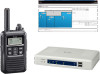
IP100H
(IP Communication terminal)
Wireless access point
IP1000C
IP100FS
(Remote communicator)
CT-23
(PTT Microphone adapter)
SM-26
(Desktop microphone)
IP Network
Connection Example
Front view
Rear view
[PWR] LED
[V/RoIP] LED
[LAN] LED
DC jack
Console port (RJ-11)
[LAN] ports (1 to 4) (RJ-45)
<INIT> button
Ground terminal
<UPDATE> button
[MSG] LED
[USB] LED
[USB] port (USB2.0)
The IP1000C and a wireless access point are required to use the IP100H, the IP communication terminal.
• Setting is needed for each IP communication terminal.
IP100FS enables you to remotely communicate with IP communication terminals connected to your IP1000C from
a PC through an IP network.