Intel BLKD102GGC2 Product Specification
Intel BLKD102GGC2 Manual
 |
View all Intel BLKD102GGC2 manuals
Add to My Manuals
Save this manual to your list of manuals |
Intel BLKD102GGC2 manual content summary:
- Intel BLKD102GGC2 | Product Specification - Page 1
® Desktop Board D102GGC2 Technical Product Specification April 2006 Order Number: D44278-001US The Intel® Desktop Board D102GGC2 may contain design defects or errors known as errata that may cause the product to deviate from published specifications. Current characterized errata - Intel BLKD102GGC2 | Product Specification - Page 2
or characteristics of any features or instructions marked "reserved" or "undefined." Intel reserves these for future definition and 1793-421-333, other Countries 708-296-9333. Intel, Pentium, and Celeron are registered trademarks of Intel Corporation or its subsidiaries in the United States and other - Intel BLKD102GGC2 | Product Specification - Page 3
connectors, power and environmental requirements, and the BIOS for the Intel® Desktop Board D102GGC2. It describes the standard product and available Board D102GGC2 A map of the resources of the Desktop Board The features supported by the BIOS Setup program A description of the BIOS error messages, - Intel BLKD102GGC2 | Product Specification - Page 4
Intel Desktop Board D102GGC2 Technical Product Specification Other Common Notation # (NxnX) GB GB/sec KB Kbit kbits/sec MB MB/sec Mbit Mbit/sec xxh x.x V * Used - Intel BLKD102GGC2 | Product Specification - Page 5
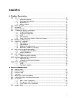
Description 1.1 Overview ...10 1.1.1 Feature Summary 10 1.1.2 Manufacturing Options 11 1.1.3 Board Layout 12 1.1.4 Block Diagram 14 1.2 Online Support ...15 1.3 Processor ...15 1.4 System Memory ...16 1.5 ATI Radeon* Xpress 200 Chipset 17 1.5.1 Graphics Subsystem 17 1.5.2 Firmware Hub (FWH - Intel BLKD102GGC2 | Product Specification - Page 6
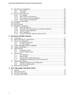
Intel Desktop Board D102GGC2 Technical Product Specification 2.9 Mechanical Considerations 52 2.9.1 Form Factor 68 3.3.2 PCI IDE Support 68 3.4 System Management BIOS (SMBIOS 69 3.5 Legacy USB Support...69 3.6 BIOS Updates ...70 3.6.1 Language Support 70 3.6.2 Custom Splash Screen - Intel BLKD102GGC2 | Product Specification - Page 7
Options 11 3. Board Components Shown in Figure 1 13 4. Supported Memory Configurations 16 5. LAN Connector LED States 28 6. Effects 18. Chassis Intrusion Connector 46 19. Serial ATA Connectors 46 20. Processor Fan Connector 46 21. Chassis Fan Connectors 46 22. Main Power Connector - Intel BLKD102GGC2 | Product Specification - Page 8
Intel Desktop Board D102GGC2 Technical Product Specification 32. Environmental Specifications 59 33. Safety Regulations ...60 34. Lead-Free Board Markings 64 35. EMC Regulations ...65 36. - Intel BLKD102GGC2 | Product Specification - Page 9
1 Product Description What This Chapter Contains 1.1 Overview ...10 1.2 Online Support ...15 1.3 Processor ...15 1.4 System Memory ...16 1.5 ATI Radeon* Xpress 200 Chipset 17 1.6 PCI Express* Connectors 24 1.7 Legacy I/O Controller 24 1.8 High Definition Audio Subsystem 26 1.9 LAN Subsystem ... - Intel BLKD102GGC2 | Product Specification - Page 10
SCH5017 I/O controller) microATX (9.60 inches by 8.60 inches [243.84 millimeters by 218.44 millimeters]) Support for the following: • Intel® Pentium® D processor in an LGA775 socket with an 800 or 533 MHz system bus • Intel® Pentium® 4 processor in an LGA775 socket with an 800 or 533 MHz system bus - Intel BLKD102GGC2 | Product Specification - Page 11
Not every manufacturing option is available in all marketing channels. Please contact your Intel representative to determine which manufacturing options are available to you. Table 2. Manufacturing Options SATA RAID Support for RAID 0 (data striping) and RAID 1 (data mirroring) on the SATA ports - Intel BLKD102GGC2 | Product Specification - Page 12
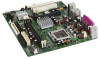
Intel Desktop Board D102GGC2 Technical Product Specification 1.1.3 Board Layout Figure 1 shows the location of the major components. A B CD E DD CC F G H BB AA Z Y I X J W V K U L T S RQP O Figure 1. Board Components - Intel BLKD102GGC2 | Product Specification - Page 13
connectors F +12V power connector (ATX12V) G Rear chassis fan connector H LGA775 processor socket I ATI Radeon Xpress 200 Northbridge J DIMM Channel A sockets [2] K Processor fan connector L Chassis intrusion connector M Legacy I/O controller N Main power connector O Diskette - Intel BLKD102GGC2 | Product Specification - Page 14
Intel Desktop Board D102GGC2 Technical Product Specification 1.1.4 Block Diagram Figure 2 is a block diagram of the major functional areas of the board. PCI Express x1 Slot 1 PCI Express x1 Interface Parallel ATA IDE Connectors (2) Parallel ATA IDE Interface LGA775 Processor Socket System Bus - Intel BLKD102GGC2 | Product Specification - Page 15
/support/motherboards/desktop http://developer.intel.com/design/motherbd/gc2/gc2_available.htm http://www.intel.com/products/index.htm http://www.intel.com/design/motherbd http://www.intel.com/design/motherbd 1.3 Processor The board is designed to support the following processors: • Intel Pentium - Intel BLKD102GGC2 | Product Specification - Page 16
Intel Desktop Board D102GGC2 Technical Product Specification 1.4 System Memory The board has two 240-pin DIMM sockets and supports the following memory features: • 1.8 V (only) DDR2 SDRAM DIMMs with gold-plated contacts • Unbuffered, single-sided or double-sided DIMMs with the following restriction - Intel BLKD102GGC2 | Product Specification - Page 17
exclusive graphics options. Either the integrated graphics processor (based on the ATI Radeon X300 core contained within the ATI Radeon Xpress 200 Northbridge the Intel BIOS. 1.5.3 USB The board supports up to eight USB 2.0 ports, supports UHCI and EHCI, and uses UHCI- and EHCI-compatible drivers. - Intel BLKD102GGC2 | Product Specification - Page 18
support the following modes: • Programmed I/O (PIO): processor controls data transfer. • 8237-style DMA: DMA offloads the processor, supporting bus supporting host and target throttling and transfer rates of up to 66 MB/sec. ATA-66 protocol is similar to Ultra DMA and is device driver compatible - Intel BLKD102GGC2 | Product Specification - Page 19
of four Serial ATA devices. A point-to-point interface is used for host to device connections, unlike Parallel ATA IDE which supports a master/slave configuration and two devices per channel. For compatibility, the underlying Serial ATA functionality is transparent to the operating system. The - Intel BLKD102GGC2 | Product Specification - Page 20
Intel Desktop Board D102GGC2 Technical Product Specification 1.5.5 Real-Time Clock, CMOS SRAM, and Battery A coin-cell battery (CR2032) powers the real-time clock and CMOS memory. - Intel BLKD102GGC2 | Product Specification - Page 21
Product Description AVVERTIMENTO Esiste il pericolo di un esplosione se la pila non viene sostituita in modo corretto. Utilizzare solo pile uguali o di tipo equivalente a quelle consigliate dal produttore. Per disfarsi delle pile usate, seguire le istruzioni del produttore. PRECAUCIÓN Existe peligro - Intel BLKD102GGC2 | Product Specification - Page 22
Intel Desktop Board D102GGC2 Technical Product Specification AWAS Risiko letupan wujud jika bateri digantikan dengan jenis yang tidak betul. Bateri sepatutnya dikitar semula jika boleh. Pelupusan - Intel BLKD102GGC2 | Product Specification - Page 23
Product Description O 23 - Intel BLKD102GGC2 | Product Specification - Page 24
Intel Desktop Board D102GGC2 Technical Product Specification 1.6 PCI Express* Connectors The board provides the following PCI Express connectors: • One PCI Express x16 connector supporting simultaneous transfer speeds up to 8 GBytes/sec • One PCI Express x1 connector. The x1 interface supports - Intel BLKD102GGC2 | Product Specification - Page 25
port mode. For information about The location of the parallel port connector Refer to Figure 6, page 43 1.7.3 Diskette Drive Controller The I/O controller supports one diskette drive. Use the BIOS Setup program to configure the diskette drive interface. For information about The location of the - Intel BLKD102GGC2 | Product Specification - Page 26
-tasking • S/N (signal-to-noise) ratio of 90 dB • Microphone input supporting: ⎯ Stereo microphone ⎯ Microphone boost # INTEGRATOR'S NOTE For the front panel Software Audio software and drivers are available from Intel's World Wide Web site. For information about Obtaining audio software and - Intel BLKD102GGC2 | Product Specification - Page 27
Product Description 1.8.2 Audio Connectors The board contains audio connector on both the back panel and the component side of the board. The front panel audio connector is a 2 x 5-pin connector that provides mic in and line out signals for front panel audio connectors. The audio subsystem - Intel BLKD102GGC2 | Product Specification - Page 28
Intel Desktop Board D102GGC2 Technical Product Specification 1.9 LAN Subsystem The LAN subsystem consists of 100 Mbits/sec data rate is selected. 1.9.1 LAN Subsystem Software LAN software and drivers are available from Intel's World Wide Web site. For information about Obtaining LAN software and - Intel BLKD102GGC2 | Product Specification - Page 29
thermal diode sensors for direct monitoring of processor temperature and ambient temperature sensing • Power Monitoring Fan monitoring can be implemented using Intel® Desktop Utilities, LANDesk* software, or Chassis Intrusion and Detection The board supports a chassis security feature that detects - Intel BLKD102GGC2 | Product Specification - Page 30
an operating system that provides full ACPI support. ACPI features include: • Plug and Play (including bus and device enumeration) • Power management control of individual devices, add-in boards (some add-in boards may require an ACPI-aware driver), video displays, and hard disk drives • Methods - Intel BLKD102GGC2 | Product Specification - Page 31
working D0 - working state. Full power > 30 W G1 - sleeping state S1 - Processor stopped C1 - stop grant D1, D2, D3 - device specification specific. 5 W < provided by battery or external source. No power to the system. Service can be performed safely. Notes: 1. Total system power is - Intel BLKD102GGC2 | Product Specification - Page 32
Intel Desktop Board D102GGC2 Technical Product Specification NOTE The use of these wake-up events from an ACPI state requires an operating system that provides full ACPI support. In addition, software, drivers, and peripherals must fully support ACPI wake events. 1.11.2 Hardware Support CAUTION - Intel BLKD102GGC2 | Product Specification - Page 33
fan tachometer input of the SMSC SCH5017 I/O controller. • All fan connectors support closed-loop fan control that can adjust the fan speed or switch the V DC connection. For information about The signal names of the processor fan connector The signal names of the chassis fan connectors Refer to - Intel BLKD102GGC2 | Product Specification - Page 34
Intel Desktop Board D102GGC2 Technical Product Specification 1.11.2.4 Instantly Available PC . The use of Instantly Available PC technology requires operating system support and PCI 2.2 compliant add-in cards, PCI Express add-in cards, and drivers. 1.11.2.5 Resume on Ring The operation of Resume on - Intel BLKD102GGC2 | Product Specification - Page 35
Product Description 1.11.2.10 +5 V Standby Power Indicator LED The +5 V standby power indicator LED shows that power is still present even when the computer appears to be off. Figure 5 shows the location of the standby power indicator LED. CAUTION If AC power has been switched off and the standby - Intel BLKD102GGC2 | Product Specification - Page 36
Intel Desktop Board D102GGC2 Technical Product Specification 36 - Intel BLKD102GGC2 | Product Specification - Page 37
2 Technical Reference What This Chapter Contains 2.1 Memory Map ...37 2.2 DMA Channels ...38 2.3 Fixed I/O Map...39 2.4 Interrupts ...40 2.5 PCI Configuration Space Map 41 2.6 PCI Conventional Interrupt Routing Map 41 2.7 Connectors...42 2.8 Jumper Block ...51 2.9 Mechanical Considerations 52 2. - Intel BLKD102GGC2 | Product Specification - Page 38
Intel Desktop Board D102GGC2 Technical Product Specification 2.2 DMA Channels Table 10. DMA Channels DMA Channel Number 0 1 2 3 4 5 6 7 Data Width 8 or 16 bits 8 or 16 bits 8 or 16 - Intel BLKD102GGC2 | Product Specification - Page 39
Technical Reference 2.3 Fixed I/O Map Table 11. I/O Map Address (hex) Size Description 0000 - 00FF 0170 - 0177 01F0 - 01F7 256 bytes 8 bytes 8 bytes Used by the Desktop Board D102GGC2. Refer to the IXP 450 data sheet for dynamic addressing information. Secondary Parallel ATA IDE channel - Intel BLKD102GGC2 | Product Specification - Page 40
Intel Desktop Board D102GGC2 Technical Product Specification 2.4 Interrupts The interrupts can be routed through either the Programmable Interrupt Controller (PIC) or the Advanced Programmable Interrupt Controller (APIC) portion of the IXP 450 Southbridge component. The PIC is supported in Windows - Intel BLKD102GGC2 | Product Specification - Page 41
Technical Reference 2.5 PCI Configuration Space Map Table 13. PCI Configuration Space Map Bus Number (hex) 00 00 00 00 00 00 00 00 00 00 00 00 00 01 01 (Notes 1 and 3) 02 (Notes 2 and 3) 02 (Note 3) 03 (Note 3) 03 (Note 3) Device Number (hex) 00 02 06 11 12 13 13 13 14 14 14 14 14 05 02 03 04 - Intel BLKD102GGC2 | Product Specification - Page 42
Intel Desktop Board D102GGC2 Technical Product Specification 2.7 Connectors CAUTION Only the following connectors have overcurrent protection: back panel USB, front panel USB, and PS/2. The other - Intel BLKD102GGC2 | Product Specification - Page 43
Technical Reference 2.7.1 Back Panel Connectors Figure 6 shows the location of the back panel connectors. The back panel connectors are color-coded. The figure legend (Table 15) lists the colors used (when applicable). AB C G I D E F Figure 6. Back Panel Connectors HJ OM18248 Table 15. - Intel BLKD102GGC2 | Product Specification - Page 44
Intel Desktop Board D102GGC2 Technical Product Specification 2.7.2 Component-side Connectors Figure 7 shows the locations of the component-side connectors. A B CDE F 10 9 21 1 3 24 G 13 12 V 7 10 - Intel BLKD102GGC2 | Product Specification - Page 45
in card connector E PCI Express x16 add-in card connector F Rear chassis fan connector G +12V power connector (ATX12V) H Processor fan connector I Chassis intrusion connector J Main power connector K Diskette drive connector L Primary parallel ATA IDE connector M Secondary parallel - Intel BLKD102GGC2 | Product Specification - Page 46
Intel Desktop Board D102GGC2 Technical Product Specification Table 18. Chassis Intrusion Connector Pin Signal Name 1 Intruder 2 Ground Table 19. Serial ATA Connectors Pin Signal Name 1 Ground 2 TXP 3 TXN 4 Ground 5 RXN 6 RXP 7 Ground Table 20. Processor Fan Connector Pin - Intel BLKD102GGC2 | Product Specification - Page 47
connector is compatible with 2 x 10 connectors previously used on Intel Desktop boards. The board supports the use of ATX12V power supplies with either 2 x 10 a 2 x 2 connector. This connector provides power directly to the processor voltage regulator and must always be used. Failure to do so will - Intel BLKD102GGC2 | Product Specification - Page 48
Intel Desktop Board D102GGC2 Technical Product Specification 2.7.2.2 Add-in Card Connectors The board has the following add-in card connectors: • PCI Express x16: one connector supporting enables PCI Conventional bus add-in boards with SMBus support to access sensor data on the board. The specific - Intel BLKD102GGC2 | Product Specification - Page 49
Technical Reference + Hard Drive Activity LED − Reset Switch +5 V DC Blue Orange 12 34 56 78 9 Red Green Single-colored Power LED + − Dual-colored Power LED − + Power Switch N/C OM18249 Figure 8. Connection Diagram for Front Panel Connector 2.7.2.4.1 Hard Drive Activity LED - Intel BLKD102GGC2 | Product Specification - Page 50
Intel Desktop Board D102GGC2 Technical Product Specification NOTE The colors listed in Table 26 and Table 27 are suggested colors only. Actual LED colors are product- - Intel BLKD102GGC2 | Product Specification - Page 51
the three modes: normal, configure, and recovery. When the jumper is set to configure mode and the computer is powered-up, the BIOS compares the processor version and the microcode version in the BIOS and reports if the two match. 1 3 OM19011 Figure 10. Location of the Jumper Block Table 28 - Intel BLKD102GGC2 | Product Specification - Page 52
Intel Desktop Board D102GGC2 Technical Product Specification 2.9 Mechanical Considerations 2.9.1 Form Factor The board is designed to fit into either a microATX or an ATX-form-factor chassis. - Intel BLKD102GGC2 | Product Specification - Page 53
. NOTE The I/O shield drawing in this document is for reference only. An I/O shield compliant with the ATX chassis specification 2.03 is available from Intel. 1.55 REF [0.061] 22.45 [0.884] 7.01 [0.276] Ø 1.00 [0.039] A 0.00 [0.00] 11.81 [0.465] 12.04 [0.474] 162.3 REF [6.390] 20 ± 0.254 - Intel BLKD102GGC2 | Product Specification - Page 54
Intel Desktop Board D102GGC2 Technical Product Specification 2.10 Electrical Considerations with a 500 mA current draw per USB port. These calculations are not based on specific processor values or memory configurations but are based on the minimum and maximum current draw possible from the - Intel BLKD102GGC2 | Product Specification - Page 55
. Table 30. Fan Connector Current Capability Fan Connector Processor fan Front chassis fan Rear chassis fan Maximum Available Current total amount of standby current required depends on the wake devices supported and manufacturing options. System integrators should refer to the power usage - Intel BLKD102GGC2 | Product Specification - Page 56
to maintain required airflow across the processor voltage regulator area. OM16996 Figure 13. Processor Heatsink for Omni-directional Airflow CAUTION remains solely with the reader. Intel makes no warranties or representations that merely following the instructions presented in this document will - Intel BLKD102GGC2 | Product Specification - Page 57
of up to 85 oC in an open chassis. Figure 14 shows the locations of the localized high temperature zones. A B D C Item A B C D Description Processor voltage regulator area Processor ATI Radeon Xpress 200 Northbridge IXP 450 Southbridge Figure 14. Localized High Temperature Zones OM19013 57 - Intel BLKD102GGC2 | Product Specification - Page 58
Xpress 200 Northbridge IXP 450 Southbridge Maximum Case Temperature For processor case temperature, see processor datasheets and processor specification updates 95 oC 85 oC For information about Intel Pentium 4 processor datasheets and specification updates Refer to Section 1.1.4, page 14 2.12 - Intel BLKD102GGC2 | Product Specification - Page 59
Technical Reference 2.13 Environmental Table 32 lists the environmental specifications for the board. Table 32. Environmental Specifications Parameter Temperature Non-Operating Operating Shock Unpackaged Packaged Vibration Unpackaged Packaged Specification -40 °C to +70 °C 0 °C to +55 °C 50 g - Intel BLKD102GGC2 | Product Specification - Page 60
- Safety - Part 1: General Requirements (International) 2.14.2 European Union Declaration of Conformity Statement We, Intel Corporation, declare under our sole responsibility that the product Intel® Desktop Board D102GGC2 is in conformity with all applicable essential requirements necessary for CE - Intel BLKD102GGC2 | Product Specification - Page 61
Technical Reference Čeština Tento výrobek odpovídá požadavkům evropských směrnic 89/336/EEC a 73/23/EEC. Dansk Dette produkt er i overensstemmelse med det europæiske direktiv 89/336/EEC & 73/23/EEC. Dutch Dit product is in navolging van de bepalingen van Europees Directief 89/336/EEC & 73/23/EEC. - Intel BLKD102GGC2 | Product Specification - Page 62
the scope of covered products, available locations, shipping instructions, terms and conditions, etc. Intel Product Recycling Program http://www.intel.com/intel/other/ehs/product_ecology/Recycling_Program.htm Deutsch Als Teil von Intels Engagement für den Umweltschutz hat das Unternehmen das - Intel BLKD102GGC2 | Product Specification - Page 63
savoir plus sur ce programme, à savoir les produits concernés, les adresses disponibles, les instructions d'expédition, les conditions générales, etc. http://www.intel.com/intel/ other/ehs/product_ecology/Recycling_Program.htm Malay Sebagai sebahagian daripada komitmennya terhadap tanggungjawab - Intel BLKD102GGC2 | Product Specification - Page 64
programın ürün kapsamı, ürün iade merkezleri, nakliye talimatları, kayıtlar ve şartlar v.s dahil bütün ayrıntılarını ögrenmek için lütfen http://www.intel.com/intel/other/ehs/product_ecology/Recycling_Program.htm Web sayfasına gidin. 2.14.3.3 Lead Free Desktop Board This desktop board is lead free - Intel BLKD102GGC2 | Product Specification - Page 65
near a radio or television receiver in a domestic environment, it may cause radio interference. Install and use the equipment according to the instruction manual. Korean Class B statement translation: this is household equipment that is certified to comply with EMC requirements. You may use this - Intel BLKD102GGC2 | Product Specification - Page 66
: CPU-D102GGC2 For information about MIC certification, go to http://support.intel.com/support/motherboards/desktop/ Taiwan BSMI (Bureau of Standards, Metrology and Inspections) mark. Includes adjacent Intel company number, D33025. Printed wiring board manufacturer's recognition mark. Consists - Intel BLKD102GGC2 | Product Specification - Page 67
Resource Configuration 68 3.4 System Management BIOS (SMBIOS 69 3.5 Legacy USB Support...69 3.6 BIOS Updates ...70 3.7 Boot Options ...71 3.8 Adjusting Boot Speed 72 3.9 BIOS Security Features 73 3.1 Introduction The boards use an Intel BIOS that is stored in the Firmware Hub (FWH) and can be - Intel BLKD102GGC2 | Product Specification - Page 68
Intel Desktop Board D102GGC2 Technical Product Specification Table 37 lists the BIOS Setup program menu features. Table 37. BIOS Setup Program Menu Bar Maintenance Main Advanced Security Clears passwords and displays processor information Displays processor support. The IDE interface supports - Intel BLKD102GGC2 | Product Specification - Page 69
manual cache size, and processor speed • Dynamic support, an SMBIOS service-level application running on a non-Plug and Play operating system can obtain the SMBIOS information. 3.5 Legacy USB Support Legacy USB support enables USB devices to be used even when the operating system's USB drivers - Intel BLKD102GGC2 | Product Specification - Page 70
. • Intel® Flash Memory Update Utility, which requires creation of a boot diskette and manual rebooting of instructions distributed with the upgrade utility before attempting a BIOS update. For information about The Intel World Wide Web site Refer to Section 1.1.4, page 14 3.6.1 Language Support - Intel BLKD102GGC2 | Product Specification - Page 71
boot device, the hard drive second, and the ATAPI CD-ROM third. The fourth device is disabled. 3.7.1 CD-ROM Boot Booting from CD-ROM is supported in compliance to the El Torito bootable CD-ROM format specification. Under the Boot menu in the BIOS Setup program, ATAPI CD-ROM is listed - Intel BLKD102GGC2 | Product Specification - Page 72
Intel Desktop Board D102GGC2 Technical Product Specification 3.8 Adjusting Boot Speed These factors It is possible to optimize the boot process to the point where the system boots so quickly that the Intel logo screen (or a custom logo splash screen) will not be seen. Monitors and hard disk drives - Intel BLKD102GGC2 | Product Specification - Page 73
Overview of BIOS Features 3.9 BIOS Security Features The BIOS includes security features that restrict access to the BIOS Setup program and who can boot the computer. A supervisor password and a user password can be set for the BIOS Setup program and for booting the computer, with the following - Intel BLKD102GGC2 | Product Specification - Page 74
Intel Desktop Board D102GGC2 Technical Product Specification 74 - Intel BLKD102GGC2 | Product Specification - Page 75
Refer to Figure 1, page 12 4.2 BIOS Beep Codes Whenever a recoverable error occurs during POST, the BIOS displays an error message describing the problem (see Table 41). Table 41. Beep Codes Type Memory error Thermal warning Pattern Three long beeps Four alternating beeps: High tone, low tone - Intel BLKD102GGC2 | Product Specification - Page 76
Intel Desktop Board D102GGC2 Technical Product Specification 4.4 Port 80h POST C0 - CF D0 - DF E0 - FF Category/Subsystem Debug codes: Can be used by any PEIM/driver for debug. Host Processors: 1F is an unrecoverable CPU error. Memory/Chipset: 2F is no memory detected or no useful memory detected. - Intel BLKD102GGC2 | Product Specification - Page 77
72 78 79 7A Description of POST Operation Host Processor Power-on initialization of the host processor (Boot Strap Processor) Host processor Cache initialization (including APs) Starting Application processor initialization SMM initialization Chipset Initializing a chipset component Memory Reading - Intel BLKD102GGC2 | Product Specification - Page 78
Intel Desktop Board Detecting presence of keyboard Enabling keyboard Clearing keyboard input buffer Instructing keyboard controller to run Self Test (PS2 only) Mouse BDS Trying boot selection y (y=0 to 15) PEI Core Started dispatching PEIMs (emitted on first report of EFI_SW_PC_INIT_BEGIN - Intel BLKD102GGC2 | Product Specification - Page 79
POST Code E7 E8 E9 EA EB EE EF Description of POST Operation DXE Drivers Waiting for user input Checking password Entering BIOS setup TBD - Flash Update Calling service ExitBootServices ( ) has been called F9 EFI runtime service SetVirtualAddressMap ( ) has been called FA EFI runtime service - Intel BLKD102GGC2 | Product Specification - Page 80
Intel Desktop Board D102GGC2 Technical Product Specification Table 45. Typical Port 80h POST Configuring memory Testing memory Loading recovery capsule Entered DXE phase Starting Application processor initialization SMM initialization Enumerating PCI busses Allocating resourced to PCI bus Detecting
-
 1
1 -
 2
2 -
 3
3 -
 4
4 -
 5
5 -
 6
6 -
 7
7 -
8
-
9
-
10
-
11
-
12
-
13
-
14
-
15
-
16
-
17
-
18
-
19
-
20
-
21
-
22
-
23
-
24
-
25
-
26
-
27
-
28
-
29
-
30
-
31
-
32
-
33
-
34
-
35
-
36
-
37
-
38
-
39
-
40
-
41
-
42
-
43
-
44
-
45
-
46
-
47
-
48
-
49
-
50
-
51
-
52
-
53
-
54
-
55
-
56
-
57
-
58
-
59
-
60
-
61
-
62
-
63
-
64
-
65
-
66
-
67
-
68
-
69
-
70
-
71
-
72
-
73
-
74
-
75
-
76
-
77
-
78
-
79
-
80
 |
 |

April 2006
Order Number:
D44278-001US
The Intel
®
Desktop Board D102GGC2 may contain design defects or errors known as errata that may cause the product to deviate from published specifications.
Current
characterized errata are documented in the Intel Desktop Board D102GGC2 Specification Update.
Intel® Desktop Board
D102GGC2
Technical Product Specification