Intel BLKD915GAGL Product Specification
Intel BLKD915GAGL Manual
 |
View all Intel BLKD915GAGL manuals
Add to My Manuals
Save this manual to your list of manuals |
Intel BLKD915GAGL manual content summary:
- Intel BLKD915GAGL | Product Specification - Page 1
Order Number: C68600-002 The Intel® Desktop Board D915GAV/D915GAG may contain design defects or errors known as errata that may cause the product to deviate from published specifications. Current characterized errata are documented in the Intel Desktop Board D915GAV/D915GAG Specification Update. - Intel BLKD915GAGL | Product Specification - Page 2
Intel Desktop Boards D915GAV and D915GAV with BIOS identifier EV91510A.86A. Changes to this specification will be published in the Intel Desktop Board D915GAV/D915GAG instructions marked "reserved" or "undefined." Intel . Intel, Pentium, and Celeron are registered trademarks of Intel Corporation or - Intel BLKD915GAGL | Product Specification - Page 3
board layout, components, connectors, power and environmental requirements, and the BIOS for these Intel® Desktop Boards: D915GAV and D915GAG Boards D915GAV and D915GAG A map of the resources of the Desktop Boards The features supported by the BIOS Setup program A description of the BIOS error - Intel BLKD915GAGL | Product Specification - Page 4
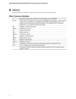
Intel Desktop Board D915GAV/D915GAG Technical Product Specification WARNING Warnings indicate conditions, N indicates component type, xn are the relative coordinates of its location on the Desktop Boards D915GAV and D915GAG, and X is the instance of the particular part at that general location. For - Intel BLKD915GAGL | Product Specification - Page 5
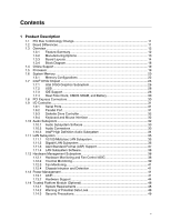
Feature Summary 12 1.3.2 Manufacturing Options 13 1.3.3 Board Layouts 14 1.3.4 Block Diagram 18 1.4 Online Support ...19 1.5 Processor ...19 1.6 System Memory ...20 1.6.1 Memory Configurations 22 1.7 Intel® 915G Chipset ...26 1.7.1 Intel 915G Graphics Subsystem 26 1.7.2 USB ...28 1.7.3 IDE - Intel BLKD915GAGL | Product Specification - Page 6
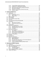
Intel Desktop Board D915GAV/D915GAG Technical Product Specification 1.14.4 1. Board Level 90 3 Overview of BIOS Features 3.1 Introduction ...91 3.2 BIOS Flash Memory Organization 92 3.3 Resource Configuration 92 3.3.1 PCI Autoconfiguration 92 3.3.2 PCI IDE Support 92 3.4 System Management BIOS - Intel BLKD915GAGL | Product Specification - Page 7
80h POST Codes 101 4.3 Bus Initialization Checkpoints 105 4.4 Speaker...106 4.5 BIOS Beep Codes...106 Figures 1. D915GAV Board Components 14 2. D915GAG Board Components 16 3. Block Diagram...18 4. Memory Channel and DIMM Configuration 22 5. Dual Channel (Interleaved) Mode Configuration with - Intel BLKD915GAGL | Product Specification - Page 8
2. Feature Summary ...12 3. Manufacturing Options 13 4. D915GAV Board Components Shown in Figure 1 15 5. D915GAG Board Components Shown in Figure 2 17 6. Supported System Bus Frequency and Memory Speed Combinations 20 7. Supported Memory Configurations 21 8. LAN Connector LED States 36 9. LAN - Intel BLKD915GAGL | Product Specification - Page 9
Program Function Keys 92 48. Boot Device Menu Options 95 49. Supervisor and User Password Functions 97 50. BIOS Error Messages 99 51. Uncompressed INIT Code Checkpoints 101 52. Boot Block Recovery Code Checkpoints 101 53. Runtime Code Uncompressed in F000 Shadow RAM 102 - Intel BLKD915GAGL | Product Specification - Page 10
Intel Desktop Board D915GAV/D915GAG Technical Product Specification x - Intel BLKD915GAGL | Product Specification - Page 11
1.2 Board Differences ...11 1.3 Overview ...12 1.4 Online Support ...19 1.5 Processor ...19 1.6 System Memory ...20 1.7 Intel® 915G Chipset called PCI Conventional. 1.2 Board Differences This TPS describes these Intel Desktop Boards: D915GAV and D915GAG. The Desktop Boards are identical with the - Intel BLKD915GAGL | Product Specification - Page 12
for an Intel® Pentium® 4 processor in an LGA775 socket with an 800 or 533 MHz system bus Memory • Four DDR SDRAM Dual Inline Memory Module (DIMM) sockets • Support for DDR 400 MHz and DDR 333 MHz DIMMs • Support for up to 4 GB of system memory Chipset Video Audio Intel® 915G Chipset, consisting - Intel BLKD915GAGL | Product Specification - Page 13
(two on the D915GAV; one on the D915GAG) • One PCI Express x16 bus add-in card connector (both boards) Instantly Available PC Technology • Support for PCI Local Bus Specification Revision 2.2 • Support for PCI Express Revision 1.0a • Suspend to RAM support • Wake on PCI, RS-232, front panel - Intel BLKD915GAGL | Product Specification - Page 14
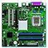
Intel Desktop Board D915GAV/D915GAG Technical Product Specification 1.3.3 Board Layouts Figure 1 shows the location of the major components on the Desktop Board D915GAV. A B D F G HI J K L CE M N O MM LL KK P JJ Q R S II T HH U FF DD BB GG EE CC AA Z Y X WV Figure 1. D915GAV - Intel BLKD915GAGL | Product Specification - Page 15
Table 4. D915GAV Board Components Shown in Figure 1 Item/callout from Figure 1 Description A Rear fan Alternate power connector N +12V power connector (ATX12V) O LGA775 processor socket P Processor fan connector Q Intel 82915G GMCH R DIMM Channel A sockets S Serial port B connector - Intel BLKD915GAGL | Product Specification - Page 16
Intel Desktop Board D915GAV/D915GAG Technical Product Specification Figure 2 shows the location of the major components on the Desktop Board D915GAG. A C E FG H I J BD K L KK M JJ II HH N O P Q GG R S T EE CC AA FF DD BB Z Y X W VU Figure 2. D915GAG Board Components Table 5 lists - Intel BLKD915GAGL | Product Specification - Page 17
Table 5. D915GAG Board Components Shown in Figure 2 Item/callout from Figure 2 Description A ATAPI CD- L +12V power connector (ATX12V) M LGA775 processor socket N Hardware monitoring and fan control ASIC O Processor fan connector P Intel 82915G GMCH Q DIMM Channel A sockets R Serial - Intel BLKD915GAGL | Product Specification - Page 18
Processor Socket System Bus (800/533 MHz) PCI Express x16 Interface PCI Express x16 Connector Intel 82915G Graphics and Memory Controller Hub (GMCH) VGA Port Channel A DIMMs (2) Display Interface Dual-Channel Memory Bus SMBus Channel B DIMMs (2) Gigabit Ethernet Controller (Optional) D915GAG - Intel BLKD915GAGL | Product Specification - Page 19
the Desktop Board D915GAG Processor data sheets ICH6 addressing Custom splash screens Audio software and utilities LAN software and drivers Visit this World Wide Web site: http://www.intel.com/design/motherbd http://support.intel.com/support/motherboards/desktop http://developer.intel.com/design - Intel BLKD915GAGL | Product Specification - Page 20
installing or upgrading memory to avoid interference with the memory retention mechanism. • To be fully compliant with all applicable DDR SDRAM memory specifications, the board should be populated with DIMMs that support the Serial Presence Detect (SPD) data structure. This allows the BIOS to read - Intel BLKD915GAGL | Product Specification - Page 21
Product Description Table 7 lists the supported DIMM configurations. Table 7. Supported Memory Configurations DIMM Capacity SDRAM Configuration Density SDRAM Organization Front-side/Back-side Number of SDRAM Devices 128 MB SS 256 Mbit 16 M x 16/empty 4 256 - Intel BLKD915GAGL | Product Specification - Page 22
Intel Desktop Board D915GAV/D915GAG Technical Product Specification 1.6.1 Memory Configurations The Intel 82915G GMCH supports two types of memory organization: • Dual channel (Interleaved) mode. This mode offers the highest throughput for real world applications. Dual channel mode is enabled when - Intel BLKD915GAGL | Product Specification - Page 23
Product Description 1.6.1.1 Dual Channel (Interleaved) Mode Configurations Figure 5 shows a dual channel configuration using two DIMMs. In this example, the DIMM0 (blue) sockets of both channels are populated with identical DIMMs. 1 GB 1 GB Channel A, DIMM 0 Channel A, DIMM 1 Channel B, DIMM 0 - Intel BLKD915GAGL | Product Specification - Page 24
Intel Desktop Board D915GAV/D915GAG Technical Product Specification Figure 7 shows a dual channel configuration using four DIMMs. In this example, the combined capacity of the two DIMMs in Channel A equal the - Intel BLKD915GAGL | Product Specification - Page 25
Product Description 1.6.1.2 Single Channel (Asymmetric) Mode Configurations NOTE Dual channel (Interleaved) mode configurations provide the highest memory throughput. Figure 8 shows a single channel configuration using one DIMM. In this example, only the DIMM0 (blue) socket of Channel A is - Intel BLKD915GAGL | Product Specification - Page 26
Intel Desktop Board D915GAV/D915GAG Technical Product Specification 1.7 Intel® 915G Chipset The Intel 915G chipset consists of the following devices: • Intel 82915G Graphics Memory Controller Hub (GMCH) with Direct Media Interface (DMI) interconnect • Intel (ADD2) card support flat panel displays - Intel BLKD915GAGL | Product Specification - Page 27
• Dynamic Video Memory Technology (DVMT) support up to 224 MB • Intel® Zoom Utility BIOS Setup program) for compatibility with legacy applications. An example of this would be when using VGA graphics under DOS. Once loaded, the operating system and graphics drivers allocate additional system memory - Intel BLKD915GAGL | Product Specification - Page 28
is available as a downloadable document. For information about Supported modes for the D915GAV board Supported modes for the D915GAG board Refer to http://www.intel.com/design/motherbd/av/av_prdoc.htm http://www.intel.com/design/motherbd/ag/ag_prdoc.htm 1.7.2 USB The boards support up to eight - Intel BLKD915GAGL | Product Specification - Page 29
The drive reports the transfer rate and translation mode to the BIOS. The boards support Laser Servo (LS-120) diskette technology through the Parallel ATA Parallel ATA IDE connector on the D915GAV board The location of the Parallel ATA IDE connector on the D915GAG board Refer to Figure 19, page 66 - Intel BLKD915GAGL | Product Specification - Page 30
connector on the D915GAG board The signal names of the SCSI hard drive activity LED connector Refer to Figure 19, page 66 Figure 20, page 68 Table 27, page 71 1.7.4 Real-Time Clock, CMOS SRAM, and Battery A coin-cell battery (CR2032) powers the real-time clock and CMOS memory. When the computer - Intel BLKD915GAGL | Product Specification - Page 31
at speeds up to 115.2 kbits/sec with BIOS support. For information about The location of the serial port A connector The location of the serial port B connector on the D915GAV board The location of the serial port B connector on the D915GAG board The signal names of the serial port B connector - Intel BLKD915GAGL | Product Specification - Page 32
Intel Desktop Board D915GAV/D915GAG Technical Product Specification 1.9.3 Diskette Drive Controller The I/O controller supports one diskette drive. Use the BIOS Setup program to configure the diskette drive interface. For information about The location of the diskette drive connector on the - Intel BLKD915GAGL | Product Specification - Page 33
drivers are available from Intel's World Wide Web site. For information about Refer to Obtaining audio software and drivers Section 1.4, page 19 1.10.2 Audio Connectors The boards , and the optional S/PDIF connector on the D915GAG board The signal names of the front panel audio connector - Intel BLKD915GAGL | Product Specification - Page 34
Intel Desktop Board D915GAV/D915GAG Technical Product Specification 1.10.3 Intel® High Definition Audio Subsystem The Intel High Definition Audio subsystem includes the following: • Intel 82801FB I/O Controller Hub (ICH6) • Realtek ALC860 audio codec • Microphone input that supports a single - Intel BLKD915GAGL | Product Specification - Page 35
LAN Subsystem NOTE The D915GAV board provides a 10/100 Mbits/sec LAN subsystem. The D915GAG board supports a manufacturing option for one Intel® 82562EZ Physical Layer Interface Device The Intel 82562EZ provides the following functions: • Basic 10/100 Ethernet LAN connectivity • Full device driver - Intel BLKD915GAGL | Product Specification - Page 36
Intel Desktop Board D915GAV/D915GAG Technical Product Specification 1.11.1.2 RJ-45 LAN Connector with support • 10/100/1000 IEEE 802.3 compliant • Compliant to 802.3x flow control support • Jumbo frame support • TCP, IP, UDP checksum offload • Automatic MDI/MDIX crossover • Full device driver - Intel BLKD915GAGL | Product Specification - Page 37
board is support for the onboard 10/100/1000 LAN subsystem, PCI Express x1 bus add-in LAN cards, and PCI Conventional bus add-in LAN cards installed in PCI Conventional bus slot 2: • Monitoring of system firmware progress events, including: ⎯ BIOS present ⎯ Primary processor initialization ⎯ Memory - Intel BLKD915GAGL | Product Specification - Page 38
Intel Desktop Board D915GAV/D915GAG Technical Product Specification 1.11.4 LAN Subsystem Software LAN software and drivers are available from Intel's World Wide Web site. For information about Refer to Obtaining LAN software and drivers direct monitoring of processor temperature and ambient - Intel BLKD915GAGL | Product Specification - Page 39
14 shows the location of the sensors and fan connectors for the D915GAV board. 13 3 1 A CB 4 1 D 13 1 3 Item A B C D E F G H HG F E OM16669 Description Thermal diode, located on processor die Remote ambient temperature sensor Ambient temperature sensor, internal to hardware monitoring - Intel BLKD915GAGL | Product Specification - Page 40
Intel Desktop Board D915GAV/D915GAG Technical Product Specification Figure 15 shows the location of the sensors and fan connectors for the D915GAG board. 3 1 A CB 4 1 D 1 3 Item A B C D E F F E OM16659 Description Thermal diode, located on processor die Remote ambient temperature sensor - Intel BLKD915GAGL | Product Specification - Page 41
an operating system that provides full ACPI support. ACPI features include: • Plug and Play (including bus and device enumeration) • Power management control of individual devices, add-in boards (some add-in boards may require an ACPI-aware driver), video displays, and hard disk drives • Methods - Intel BLKD915GAGL | Product Specification - Page 42
Intel Desktop Board D915GAV/D915GAG Technical Product Specification Table 10 lists the system states based on how long the power switch is pressed, depending on how ACPI is configured with - Intel BLKD915GAGL | Product Specification - Page 43
states supported by the boards along with the associated system power targets. See the ACPI specification for a complete description of the various system and power states. Table 11. Power States and Targeted System Power Global States G0 - working state Sleeping States S0 - working Processor - Intel BLKD915GAGL | Product Specification - Page 44
Intel Desktop Board D915GAV/D915GAG : For LAN and PME# signal, S5 is disabled by default in the BIOS Setup program. Setting this option to Power On will enable a wake-up ACPI support. In addition, software, drivers, and peripherals must fully support ACPI wake events. 1.13.2 Hardware Support - Intel BLKD915GAGL | Product Specification - Page 45
from an ACPI state requires an operating system that provides full ACPI support. 1.13.2.1 Power Connector ATX12V-compliant power supplies can turn off the D915GAV board The location of the fan connectors and sensors for thermal monitoring on the D915GAG board The signal names of the processor fan - Intel BLKD915GAGL | Product Specification - Page 46
. Add-in boards that also support this specification can participate in power management and can be used to wake the computer. The use of Instantly Available PC technology requires operating system support and PCI 2.2 compliant add-in cards, PCI Express add-in cards, and drivers. 1.13.2.5 Resume - Intel BLKD915GAGL | Product Specification - Page 47
, S4, or S5 state (with Wake on PME enabled in BIOS). 1.13.2.9 WAKE# Signal Wake-up Support When the WAKE# signal on the PCI Express bus is asserted, the standby power indicator LED in the D915GAV board. The LED is in the same location on the D915GAG board. CAUTION If AC power has been switched off - Intel BLKD915GAGL | Product Specification - Page 48
• Intel Desktop Board D915GAV or D915GAG • instructions below may cause you to lose data. Read and follow these instructions failure and/or replacement of the motherboard, recovery procedures may allow migratable Ownership/contents may be cleared (via a BIOS switch) to allow for the transfer of - Intel BLKD915GAGL | Product Specification - Page 49
Product Description 1.14.3 Security Precautions Security, like any other aspect of computer maintenance requires planning. What is unique about security has to do with understanding who "friends" and adversaries are. The TPM provides mechanisms to enable the owner/user to protect their information - Intel BLKD915GAGL | Product Specification - Page 50
Intel Desktop Board D915GAV/D915GAG Technical Product Specification 1.14.3.2 Emergency Recovery File Back Up Procedures The Emergency Recovery Token (SPEmRecToken.xml) must be saved or moved to a removable media (floppy, - Intel BLKD915GAGL | Product Specification - Page 51
the splash screen (or POST screen), press the key to enter BIOS. 2. Use the arrow keys to go to the Advanced Menu, select Peripheral Configuration Wizard. 3. Create Owner password (before creating any password, review the Password Recommendations made earlier in this document). 4. Create - Intel BLKD915GAGL | Product Specification - Page 52
Intel Desktop Board D915GAV/D915GAG Technical Product Specification 15. Follow the instructions and create and document the locations for is not present when a new key is generated, then keys will have to be manually backed up using the Key Transfer Manager when the removable media is available. 19. - Intel BLKD915GAGL | Product Specification - Page 53
and might restore access to encrypted data. (Review the Recovery Procedures for detailed instructions). The TPM may be cleared to transfer ownership the configuration jumper on the board to pins 2-3. 3. Restore power to the PC and power on. 4. System should automatically enter BIOS setup. 5. Use the - Intel BLKD915GAGL | Product Specification - Page 54
Intel Desktop Board D915GAV/D915GAG Technical Product Specification 1.14.9 Software Support • For assistance with the Infineon Security Platform Software, visit the web at: http://www.infineon.com • For assistance with the Wave System EMBASSY Trust Suite, - Intel BLKD915GAGL | Product Specification - Page 55
2.2.1 Addressable Memory The board utilizes 4 GB of addressable system memory. Typically the address space that is allocated for PCI Conventional bus add-in cards, PCI Express configuration space, BIOS (firmware hub), and chipset overhead resides above the top of DRAM (total system memory). On - Intel BLKD915GAGL | Product Specification - Page 56
Intel Desktop Board D915GAV/D915GAG Technical Product Specification • MCH base address registers, internal graphics ranges, PCI Express ports (up to 512 MB) • Memory-mapped I/O that is dynamically allocated for PCI Conventional and PCI Express add- in cards The amount of installed memory that can - Intel BLKD915GAGL | Product Specification - Page 57
(open to the PCI Conventional bus). Dependent on video adapter used. Video memory and BIOS Extended BIOS data (movable by memory manager software) Extended conventional memory Conventional memory 2.3 DMA Channels Table 14. DMA Channels DMA Channel Number 0 1 2 3 4 5 6 7 Data Width 8 or 16 bits - Intel BLKD915GAGL | Product Specification - Page 58
Intel Desktop Board D915GAV/D915GAG Technical Product Specification 2.4 Fixed I/O Map Table 15. I/O Map Address (hex) Size Description 0000 - 00FF 0170 - 0177 256 bytes 8 bytes Used by the Desktop Board D915GAV/D915GAG. Refer to the ICH6 data sheet for dynamic addressing information. - Intel BLKD915GAGL | Product Specification - Page 59
(Note 3) 03 00 PCI Conventional bus connector 4 (Note 2) (Note 3) 08 00 Intel 82562EZ 10/100 Mbits/sec LAN PLC (if present) Notes: 1. Present only when a PCI Express x16 graphics card is installed. 2. Not present on the D915GAG board. 3. Bus number is dynamic and can change based on add-in - Intel BLKD915GAGL | Product Specification - Page 60
Intel Desktop Board D915GAV/D915GAG Technical Product Specification 2.6 Interrupts The interrupts can be routed through either the Programmable Interrupt Controller (PIC) or the Advanced Programmable Interrupt Controller (APIC) portion of the ICH6 component. The PIC is supported in Windows 98 SE - Intel BLKD915GAGL | Product Specification - Page 61
or from a PCI Conventional add-in card connect to one of these PIRQ signals. Some PCI Conventional interrupt sources are electrically tied together on the board and therefore share the same interrupt. Table 18 shows an example of how the PIRQ signals are routed. For example, using Table 18 as - Intel BLKD915GAGL | Product Specification - Page 62
Intel Desktop Board D915GAV/D915GAG Technical Product Specification Table 18. PCI Interrupt Routing Map PCI Interrupt Source ICH6 LAN PCI bus connector 1 PCI bus connector 2 PCI bus connector 3 (Note) PCI bus connector 4 (Note) PIRQA PIRQB INTD INTC Note: Not present on the D915GAG board. ICH6 - Intel BLKD915GAGL | Product Specification - Page 63
by the external devices could cause damage to the computer, the power cable, and the external devices themselves. This section describes the board's connectors. The connectors can be divided into these groups: • Back panel I/O connectors (see page 64) • Component-side I/O connectors (see page 65) 63 - Intel BLKD915GAGL | Product Specification - Page 64
Intel Desktop Board D915GAV/D915GAG Technical Product Specification 2.8.1 Back Panel Connectors Figure 18 shows the location of the back panel connectors. The back panel connectors are color-coded. The figure - Intel BLKD915GAGL | Product Specification - Page 65
Port D (Lime Green) H Mic in/Retasking Port B (Pink) I IEEE-1394a (optional) J USB ports (two) K LAN L USB ports (two) NOTE The D915GAG board supports a manufacturing option for no LAN subsystem. On D915GAG boards with no LAN subsystem, the back panel LAN connector is not present. 65 - Intel BLKD915GAGL | Product Specification - Page 66
Intel Desktop Board D915GAV/D915GAG Technical Product Specification 2.8.2 Component-side Connectors Figure 19 shows the locations of the component-side connectors on the D915GAV board. B D FH J L AC E GI K M N P O 13 12 9 10 3 4 1 1 2 1 10 12 10 1 3 1 4 4 13 12 10 11 1 3 9 1 11 - Intel BLKD915GAGL | Product Specification - Page 67
chassis fan connector 1 O Alternate power connector P +12V power connector (ATX12V) Q SCSI LED (optional) R Serial port B (optional) S Processor fan connector T Power connector U Diskette drive connector V Parallel ATA IDE connector W Chassis intrusion connector X Front chassis - Intel BLKD915GAGL | Product Specification - Page 68
Intel Desktop Board D915GAV/D915GAG Technical Product Specification Figure 20 shows the locations of the component-side connectors on the D915GAG board. BD AC E F G I H BB AA 12 9 10 3 4 1 1 1 3 1 44 13 12 10 11 2 1 10 12 10 Z 9 1 11 2 1 1 3 4 J 1 12 Y 10 X W 1 2 1 VT R P US Q - Intel BLKD915GAGL | Product Specification - Page 69
F PCI Express x16 bus add-in card connector G Rear chassis fan connector H Alternate power connector I +12V power connector (ATX12V) J Processor fan connector K Serial port B (optional) L SCSI LED (optional) M Power connector N Diskette drive connector O Parallel ATA IDE connector - Intel BLKD915GAGL | Product Specification - Page 70
Intel Desktop Board D915GAV/D915GAG Technical Product Specification Table 22. S/PDIF Connector (Optional) Pin Signal Name 1 +5 V 2 S/PDIF Output 3 Ground Table 23. ATAPI CD-ROM Connector (Optional) Pin Signal Name 1 Left - Intel BLKD915GAGL | Product Specification - Page 71
29. Processor Fan Connector Pin Signal Name 1 Ground 2 +12 V 3 FAN_TACH 4 FAN_CONTROL 2.8.2.1 Chassis Fan Connectors The D915GAV board has three 1 • Rear chassis fan 2 • ATX fan connector (optional) The D915GAG board has two chassis fan connectors: • Front chassis fan • Rear chassis fan - Intel BLKD915GAGL | Product Specification - Page 72
Intel Desktop Board D915GAV/D915GAG Technical Product Specification 2.8.2.2 Power Supply Connectors The board has three power supply connectors: • Main power - a 2 x 12 connector. This connector is compatible with 2 x 10 connectors previously used on Intel Desktop boards. The board supports the use - Intel BLKD915GAGL | Product Specification - Page 73
simultaneous transfer speeds up to 8 GBytes/sec. • PCI Express x1: the D915GAV board has two PCI Express x1 connectors; the D915GAG board has one PCI Express x1 connector. The x1 interfaces support simultaneous transfer speeds up to 500 MBytes/sec. • PCI Conventional (rev 2.2 compliant) bus - Intel BLKD915GAGL | Product Specification - Page 74
Intel Desktop Board D915GAV/D915GAG Technical Product Specification 2.8.2.4 Auxiliary Front Panel Power/Sleep LED Connector Pins 1 and 3 of this connector duplicate the signals on pins 2 and 4 of the front panel - Intel BLKD915GAGL | Product Specification - Page 75
5 and 7 [Purple] can be connected to a momentary single pole, single throw (SPST) type switch that is normally open. When the switch is closed, the board resets and runs the POST. 2.8.2.5.3 Power/Sleep LED Connector [Green] Pins 2 and 4 [Green] can be connected to a one- or two-color LED. Table 36 - Intel BLKD915GAGL | Product Specification - Page 76
Intel Desktop Board D915GAV/D915GAG Technical Product Specification 2.8.2.6 Front Panel USB Connectors Figure 22 is a connection diagram for the front panel USB connectors. # INTEGRATOR'S NOTES • The +5 V DC power on the - Intel BLKD915GAGL | Product Specification - Page 77
location on the D915GAG board.) The jumper block determines the BIOS Setup program's mode. Table 38 describes the jumper settings for the three modes: normal, configure, and recovery. When the jumper is set to configure mode and the computer is powered-up, the BIOS compares the processor version and - Intel BLKD915GAGL | Product Specification - Page 78
Intel Desktop Board D915GAV/D915GAG Technical Product Specification 2.10 Mechanical Considerations 2.10.1 D915GAV Board Form Factor The D915GAV board is designed to fit into an ATX-form-factor chassis. Figure 25 illustrates the mechanical form factor of the board. Dimensions are given in inches [ - Intel BLKD915GAGL | Product Specification - Page 79
Technical Reference 2.10.2 D915GAG Board Form Factor The D915GAG board is designed to fit into either a microATX or an ATX-form-factor chassis. Figure 26 illustrates the mechanical form factor of the board. Dimensions are given in inches [millimeters]. The outer dimensions are 9.60 inches by 9.60 - Intel BLKD915GAGL | Product Specification - Page 80
Intel Desktop Board D915GAV/D915GAG Technical Product Specification 2.10.3 I/O Shield The back panel I/O shield for the boards must meet specific dimension and material requirements. Systems based on these boards need the back panel I/O shield to pass certification testing. Figure 27 shows the I/O - Intel BLKD915GAGL | Product Specification - Page 81
draw per USB port. These calculations are not based on specific processor values or memory configurations but are based on the minimum and maximum current draw possible from the board's power delivery subsystems to the processor, memory, and USB ports. Use the datasheets for add-in cards, such - Intel BLKD915GAGL | Product Specification - Page 82
Intel Desktop Board D915GAV/D915GAG Technical Product Specification 2.11.3 Fan Connector Current Capability CAUTION The processor fan must be connected to the processor fan connector, not to a chassis fan connector. Connecting the processor fan to a chassis fan connector may result in onboard - Intel BLKD915GAGL | Product Specification - Page 83
in reduced performance of both the processor and/or voltage regulator or, in some instances, damage to the board. For a list of chassis that have been tested with Intel desktop boards please refer to the following website: http://developer.intel.com/design/motherbd/cooling.htm All responsibility - Intel BLKD915GAGL | Product Specification - Page 84
Intel Desktop Board D915GAV/D915GAG Technical Product Specification CAUTION Ensure that proper airflow is maintained in the processor voltage regulator circuit. Failure to do so may result in damage to the voltage regulator circuit. The processor voltage regulator area (item A in Figure 29) can - Intel BLKD915GAGL | Product Specification - Page 85
board. Table 41. Thermal Considerations for Components Component Intel Pentium 4 processor Intel 82915G GMCH Intel 82801FB ICH6 Maximum Case Temperature For processor case temperature, see processor datasheets and processor 55 ºC. The MTBF for the D915GAV and D915GAG boards is 102,038 hours. 85 - Intel BLKD915GAGL | Product Specification - Page 86
Intel Desktop Board D915GAV/D915GAG Technical Product Specification 2.14 Environmental Table 42 lists the environmental specifications for the board. Table 42. Environmental Specifications Parameter Temperature Non-Operating Operating Shock Unpackaged Packaged Vibration Unpackaged Packaged - Intel BLKD915GAGL | Product Specification - Page 87
Equipment - Safety - Part 1: General Requirements (International) 2.15.2 EMC Regulations Table 44 lists the EMC regulations the Desktop Boards D915GAV and D915GAG comply with when correctly installed in a compatible host system. Table 44. EMC Regulations Regulation FCC (Class B) ICES-003 - Intel BLKD915GAGL | Product Specification - Page 88
energy and, if not installed and used in accordance with the instructions, may cause harmful interference to radio communications. However, there Statement We, Intel Corporation, declare under our sole responsibility that the product: Intel Desktop Boards D915GAV and D915GAG are in conformity - Intel BLKD915GAGL | Product Specification - Page 89
be regulated upon disposal: lead solder on the printed wiring board assembly. 2.15.4.2 Recycling Considerations Intel encourages its customers to recycle its products and their components (e.g., batteries, circuit boards, plastic enclosures, etc.) whenever possible. In the U.S., a list of recyclers - Intel BLKD915GAGL | Product Specification - Page 90
/Canada Recognized Component mark. Includes adjacent UL file number for Intel Desktop Boards: E210882 (component side). FCC Declaration of Conformity logo mark for Class B equipment; includes Intel name and D915GAV or D915GAG model designation (component side). Marking CE mark. Declares compliance - Intel BLKD915GAGL | Product Specification - Page 91
3.2 BIOS Flash Memory Organization 92 3.3 Resource Configuration 92 3.4 System Management BIOS (SMBIOS 93 3.5 Legacy USB Support...93 3.6 BIOS Updates ...94 3.7 Boot Options ...95 3.8 Fast Booting Systems with Intel® Rapid BIOS Boot 96 3.9 BIOS Security Features 97 3.1 Introduction The boards - Intel BLKD915GAGL | Product Specification - Page 92
Intel Desktop Board D915GAV/D915GAG Technical Product Specification Table 46 lists the BIOS Setup program menu features. Table 46. BIOS Setup Program Menu Bar Maintenance Main Advanced Security Clears passwords and displays processor information Displays processor and memory configuration - Intel BLKD915GAGL | Product Specification - Page 93
• Resource data, such as memory size, cache size, and processor speed • Dynamic data, such as event detection and error logging Non-Plug and Play operating systems, such as Windows NT*, require an additional interface for obtaining the SMBIOS information. The BIOS supports an SMBIOS table interface - Intel BLKD915GAGL | Product Specification - Page 94
an incompatible BIOS. NOTE Review the instructions distributed with the upgrade utility before attempting a BIOS update. For information about The Intel World Wide Web site Refer to Section 1.4, page 19 3.6.1 Language Support The BIOS Setup program and help messages are supported in US - Intel BLKD915GAGL | Product Specification - Page 95
ATAPI CD-ROM third. The fourth device is disabled. 3.7.1 CD-ROM Boot Booting from CD-ROM is supported in compliance to the El Torito bootable CD-ROM format specification. Under the Boot menu in the BIOS Setup program, ATAPI CD-ROM is listed as a boot device. Boot devices are defined in priority - Intel BLKD915GAGL | Product Specification - Page 96
Intel Desktop Board D915GAV/D915GAG Technical Product Specification 3.8 Fast Booting Systems with Intel® Rapid BIOS Boot These factors affect system boot speed: • Selecting and configuring peripherals properly • Using an optimized BIOS, such as the Intel® Rapid BIOS 3.8.1 Peripheral Selection and - Intel BLKD915GAGL | Product Specification - Page 97
Setup program. This is the user mode. • If only the supervisor password is set, pressing the key at the password prompt of the BIOS Setup program allows the user restricted access to Setup. • If both the supervisor and user passwords are set, users can enter either the supervisor password - Intel BLKD915GAGL | Product Specification - Page 98
Intel Desktop Board D915GAV/D915GAG Technical Product Specification 98 - Intel BLKD915GAGL | Product Specification - Page 99
messages and provides a brief description of each. Table 50. BIOS Error Messages Error Message GA20 Error Pri Master HDD Error Pri Slave HDD Error Pri Master Drive - ATAPI Incompatible Pri Slave Drive - ATAPI Incompatible A: Drive Error Cache Memory Bad CMOS Battery Low CMOS Display Type Wrong CMOS - Intel BLKD915GAGL | Product Specification - Page 100
Intel Desktop Board D915GAV/D915GAG Technical Product Specification Table 50. BIOS Error memory was removed then memory may be bad. Memory Size Increased Memory size has increased since the last boot. If no memory was added there may be a problem with the system. Memory Size Changed Memory - Intel BLKD915GAGL | Product Specification - Page 101
of the POST codes generated by the BIOS. Table 51 defines the uncompressed INIT CPU ID saved, and going to 4 GB flat mode. Do necessary chipset initialization, start memory refresh, and do memory sizing. Verify base memory controller. Initialize extra (Intel Recovery) Module. Initialize floppy - Intel BLKD915GAGL | Product Specification - Page 102
Intel Desktop Board D915GAV/D915GAG soft reset/power-on. BIOS stack set. Going to disable cache if any. POST code to be uncompressed. CPU init and CPU data area init to begin. 8254 timer test about to start. About to start memory refresh test. Memory Refresh line is toggling. Going to check 15 µs ON/ - Intel BLKD915GAGL | Product Specification - Page 103
adjusted due to relocation/ shadow. Memory test above 1M to follow. Memory testing/initialization above 1M complete. Going to save memory size information. Memory size information is saved. CPU registers are saved. Going to enter in real mode. Shutdown successful, CPU in real mode. Going to disable - Intel BLKD915GAGL | Product Specification - Page 104
Intel Desktop Board D915GAV/D915GAG -key checking over. To check for memory size mismatch with CMOS. Memory size check done. To display soft error message displayed. PS/2 Mouse check and extended BIOS data area allocation to be done. Setup multiprocessor support (if present). Put CGA INT10 - Intel BLKD915GAGL | Product Specification - Page 105
to INT-19 boot loader. 4.3 Bus Initialization Checkpoints The system BIOS gives control to the different buses at several checkpoints to do various these WORD checkpoints, the low byte of the checkpoint is the system BIOS checkpoint from which the control is passed to the different bus routines. - Intel BLKD915GAGL | Product Specification - Page 106
Intel Desktop Board D915GAV/D915GAG Technical Product Specification Table 56 describes the lower POST completes normally, the BIOS issues one short beep before passing control to the operating system. Table 57. Beep Codes Beep 1 3 6 7 8 Description CPU error Memory error System failure System
-
 1
1 -
 2
2 -
 3
3 -
 4
4 -
 5
5 -
 6
6 -
 7
7 -
8
-
9
-
10
-
11
-
12
-
13
-
14
-
15
-
16
-
17
-
18
-
19
-
20
-
21
-
22
-
23
-
24
-
25
-
26
-
27
-
28
-
29
-
30
-
31
-
32
-
33
-
34
-
35
-
36
-
37
-
38
-
39
-
40
-
41
-
42
-
43
-
44
-
45
-
46
-
47
-
48
-
49
-
50
-
51
-
52
-
53
-
54
-
55
-
56
-
57
-
58
-
59
-
60
-
61
-
62
-
63
-
64
-
65
-
66
-
67
-
68
-
69
-
70
-
71
-
72
-
73
-
74
-
75
-
76
-
77
-
78
-
79
-
80
-
81
-
82
-
83
-
84
-
85
-
86
-
87
-
88
-
89
-
90
-
91
-
92
-
93
-
94
-
95
-
96
-
97
-
98
-
99
-
100
-
101
-
102
-
103
-
104
-
105
-
106
 |
 |

December 2004
Order Number:
C68600-002
The Intel
®
Desktop Board D915GAV/D915GAG may contain design defects or errors known as errata that may cause the product to deviate from published specifications.
Current characterized errata are documented in the Intel Desktop Board D915GAV/D915GAG Specification Update.
Intel
®
Desktop Boards
D915GAV/D915GAG
Technical Product Specification