Intel BLKD945GTPLR Product Specification
Intel BLKD945GTPLR - Desktop Board D945GTP Manual
 |
UPC - 735858174725
View all Intel BLKD945GTPLR manuals
Add to My Manuals
Save this manual to your list of manuals |
Intel BLKD945GTPLR manual content summary:
- Intel BLKD945GTPLR | Product Specification - Page 1
® Desktop Board D945GTP Technical Product Specification May 2005 Order Number: D14070-001US The Intel® Desktop Board D945GTP may contain design defects or errors known as errata that may cause the product to deviate from published specifications. Current characterized errata - Intel BLKD945GTPLR | Product Specification - Page 2
not be supported without further evaluation by Intel. Intel Corporation may have any features or instructions marked "reserved" or "undefined." Intel reserves these other Countries 708-296-9333. Intel, Pentium, and Celeron are registered trademarks of Intel Corporation or its subsidiaries in the - Intel BLKD945GTPLR | Product Specification - Page 3
connectors, power and environmental requirements, and the BIOS for the Intel® Desktop Board D945GTP. It describes the standard product and available Board D945GTP A map of the resources of the Desktop Board The features supported by the BIOS Setup program A description of the BIOS error messages, - Intel BLKD945GTPLR | Product Specification - Page 4
Intel Desktop Board D945GTP Technical Product Specification Other Common Notation # (NxnX) GB GB/sec Gbits/sec KB Kbit kbits/sec MB MB/sec Mbit Mbit/sec - Intel BLKD945GTPLR | Product Specification - Page 5
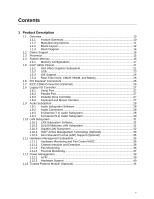
Board Layout 12 1.1.4 Block Diagram 14 1.2 Online Support ...15 1.3 Processor ...15 1.4 System Memory ...16 1.4.1 Memory Configurations 17 1.5 Intel® 945G Chipset ...21 1.5.1 Intel 945G Graphics Subsystem 21 1.5.2 USB ...23 1.5.3 IDE Support 24 1.5.4 Real-Time Clock, CMOS SRAM, and Battery - Intel BLKD945GTPLR | Product Specification - Page 6
Intel Desktop Board D945GTP Technical Product Specification 2 Technical Reference 2.1 Introduction ...45 2.2 Memory Resources ...45 80 3.3.2 PCI IDE Support 80 3.4 System Management BIOS (SMBIOS 81 3.5 Legacy USB Support...81 3.6 BIOS Updates ...82 3.6.1 Language Support 82 3.6.2 Custom Splash - Intel BLKD945GTPLR | Product Specification - Page 7
Dimensions...66 26. I/O Shield Dimensions for Boards with the 8-Channel (7.1) Audio Subsystem 67 27. I/O Shield Dimensions for Boards with the 6-Channel (5.1) Audio Subsystem 68 28. Processor Heatsink for Omni-directional Airflow 71 29. Localized High Temperature Zones 72 vii - Intel BLKD945GTPLR | Product Specification - Page 8
Intel Desktop Board D945GTP Technical Product Specification Tables 1. Feature Summary ...10 2. Manufacturing Options 11 3. Board Components Shown in Figure 1 13 4. Supported Connector (Optional 58 22. Serial ATA Connectors 58 23. Processor Fan Connector 59 24. Front and Rear Chassis Fan - Intel BLKD945GTPLR | Product Specification - Page 9
1 Product Description What This Chapter Contains 1.1 Overview ...10 1.2 Online Support ...15 1.3 Processor ...15 1.4 System Memory ...16 1.5 Intel® 945G Chipset ...21 1.6 PCI Express* Connectors 26 1.7 IEEE-1394a Connectors (Optional 26 1.8 Legacy I/O Controller 27 1.9 Audio Subsystem ...28 1.10 - Intel BLKD945GTPLR | Product Specification - Page 10
the board. Table 1. Feature Summary Form Factor microATX (9.60 inches by 9.60 inches [243.84 millimeters by 243.84 millimeters]) Processor Support for an Intel® Pentium® 4 processor in an LGA775 socket with a 1066, 800, or 533 MHz system bus Memory • Four 240-pin DDR2 SDRAM Dual Inline Memory - Intel BLKD945GTPLR | Product Specification - Page 11
/82573V/82574V Gigabit Ethernet Controller • 10/100 Mbits/sec LAN subsystem using the Intel® 82562GX/82562GZ Platform LAN Connect (PLC) device Intel® 82801GR I/O Controller Hub (ICH7-R) for RAID support (levels 0,1, 0+1, and 5) on the SATA interface SCSI Hard Drive Activity LED Connector Allows - Intel BLKD945GTPLR | Product Specification - Page 12
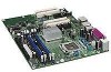
Intel Desktop Board D945GTP Technical Product Specification 1.1.3 Board Layout Figure 1 shows the location of the major components. A D B CE F G H FF EE I DD CC J BB AA K Z L Y M X N V TS R Q W U Figure 1. - Intel BLKD945GTPLR | Product Specification - Page 13
add-in card connector F Back panel connectors G +12V power connector (ATX12V) H Rear chassis fan connector I LGA775 processor socket J Intel 82945G GMCH K Processor fan connector L DIMM Channel A sockets [2] M DIMM Channel B sockets [2] N SCSI LED connector (optional) O Legacy - Intel BLKD945GTPLR | Product Specification - Page 14
Front Panel USB Ports Parallel ATA IDE Connector Parallel ATA IDE Interface LGA775 Processor Socket System Bus (1066/800/533 MHz) PCI Express x16 Interface PCI Express x16 Connector Intel 945G Chipset Intel 82945G Graphics and Memory Controller Hub (GMCH) Legacy I/O Controller LPC Bus Serial - Intel BLKD945GTPLR | Product Specification - Page 15
D945GTP Processor data sheets ICH7 addressing Custom splash screens Audio software and utilities LAN software and drivers Supported video modes Intel® Active Management Technology Visit this World Wide Web site: http://www.intel.com/design/motherbd http://support.intel.com/support/motherboards - Intel BLKD945GTPLR | Product Specification - Page 16
Intel Desktop Board D945GTP Technical Product Specification 1.4 System Memory The board has four DIMM sockets and support the following memory features: • 1.8 V (only) DDR2 SDRAM DIMMs with gold-plated contacts • Unbuffered, single-sided or double-sided DIMMs with the following restriction: Double- - Intel BLKD945GTPLR | Product Specification - Page 17
Product Description 1.4.1 Memory Configurations The Intel 82945G GMCH supports two types of memory organization: • Dual channel (Interleaved) mode. This mode offers the highest throughput for real world applications. Dual channel mode is enabled when - Intel BLKD945GTPLR | Product Specification - Page 18
Intel Desktop Board D945GTP Technical Product Specification 1.4.1.1 Dual Channel (Interleaved) Mode Configurations Figure 4 shows a dual channel configuration using two DIMMs. In this example, the DIMM0 (blue) - Intel BLKD945GTPLR | Product Specification - Page 19
Product Description Figure 6 shows a dual channel configuration using four DIMMs. In this example, the combined capacity of the two DIMMs in Channel A equal the combined capacity of the two DIMMs in Channel B. Also, the DIMMs are matched between DIMM0 and DIMM1 of both channels. 256 MB 512 MB 256 - Intel BLKD945GTPLR | Product Specification - Page 20
Intel Desktop Board D945GTP Technical Product Specification 1.4.1.2 Single Channel (Asymmetric) Mode Configurations NOTE Dual channel (Interleaved) mode configurations provide the highest memory throughput. Figure 7 shows a single - Intel BLKD945GTPLR | Product Specification - Page 21
is disabled. 1.5.1.1 Intel® GMA950 Graphics Controller The Intel GMA950 graphics controller features the following: • 400 MHz core frequency • High ⎯ Maximum 3D supported resolution of 1600 x 1200 x 32 at 85 Hz ⎯ Vertex cache ⎯ Anti-aliased lines ⎯ OpenGL* version 1.4 support with vertex buffer - Intel BLKD945GTPLR | Product Specification - Page 22
ADD2/ADD2+ card • Dynamic Video Memory Technology (DVMT) support up to 224 MB • Intel® Zoom Utility For information about DVMT Obtaining graphics software graphics under DOS. Once loaded, the operating system and graphics drivers allocate additional system memory to the graphics buffer as needed - Intel BLKD945GTPLR | Product Specification - Page 23
for the Intel GMA950 graphics controller is available as a downloadable document. For information about Supported video modes for the board Refer to Section 1.2, page 15 1.5.2 USB The board supports up to eight USB 2.0 ports, supports UHCI and EHCI, and uses UHCI- and EHCI-compatible drivers. The - Intel BLKD945GTPLR | Product Specification - Page 24
supports the following modes: • Programmed I/O (PIO): processor controls data transfer. • 8237-style DMA: DMA offloads the processor, supporting bus supporting host and target throttling and transfer rates of up to 66 MB/sec. ATA-66 protocol is similar to Ultra DMA and is device driver compatible - Intel BLKD945GTPLR | Product Specification - Page 25
about The location of the Serial ATA IDE connectors Refer to Figure 20, page 56 1.5.3.3 Serial ATA RAID (Optional) The optional ICH7-R supports the following RAID (Redundant Array of Independent Drives) levels: • RAID 0 - data striping. Multiple physical drives can be teamed together to create one - Intel BLKD945GTPLR | Product Specification - Page 26
Intel Desktop Board D945GTP Technical Product Specification 1.5.4 Real-Time Clock, CMOS SRAM, and mechanism • Automatic discovery, link training, and initialization • Support for Active State Power Management (ASPM) • SMBus 2.0 support • Wake# signal supporting wake events from ACPI S1, S3, S4, or - Intel BLKD945GTPLR | Product Specification - Page 27
information about The location of the parallel port connector Refer to Figure 19, page 55 1.8.3 Diskette Drive Controller The legacy I/O controller supports one diskette drive. Use the BIOS Setup program to configure the diskette drive interface. For information about The location of the diskette - Intel BLKD945GTPLR | Product Specification - Page 28
includes the following: • Intel 82801G I/O Controller Hub (ICH7) • Sigmatel 9223 audio codec • Microphone input that supports a single dynamic, condenser, or electret microphone The back panel audio connectors are configurable through the audio device drivers. The available configurable audio - Intel BLKD945GTPLR | Product Specification - Page 29
Audio Connector Options for 8-Channel (7.1) Audio Subsystem Figure 10 is a block diagram of the 8-channel (7.1) audio subsystem. 82801G I/O Controller Hub (ICH7) Intel High Definition Audio Link Sigmatel 9223 Audio Codec Line Out Mic In Line In/Side Surround L-R/Retasking Jack Line Out/Retasking - Intel BLKD945GTPLR | Product Specification - Page 30
Intel 82801G I/O Controller Hub (ICH7) • Sigmatel 9220 audio codec • Microphone input that supports a single dynamic, condenser, or electret microphone The back panel audio connectors are configurable through the audio device drivers Controller Hub (ICH7) Intel High Definition Audio Link Sigmatel - Intel BLKD945GTPLR | Product Specification - Page 31
protocol engine • LAN connect interface that supports the 82562GX and 82562GZ • PCI Conventional bus power management ⎯ Supports ACPI technology ⎯ Supports LAN wake capabilities 1.10.1 LAN Subsystem Software LAN software and drivers are available from Intel's World Wide Web site. For information - Intel BLKD945GTPLR | Product Specification - Page 32
IP, UDP checksum offload • Transmit TCP segmentation • Advanced packet filtering • Full device driver compatibility • PCI Express Power Management Support The 82573E Gigabit Ethernet Controller also supports the following: • Intel® Active Management Technology • Alert Standard Format (ASF) 2.0. 32 - Intel BLKD945GTPLR | Product Specification - Page 33
, and protect all of their computing assets, regardless of system state in the manner described below. • Discovering hardware and software computing assets: ⎯ Intel AMT stores hardware and software asset information in non-volatile memory and allows IT to read the asset information anytime, even if - Intel BLKD945GTPLR | Product Specification - Page 34
problems quickly to reduce end-user downtime • Protecting the enterprise against malicious software attacks: ⎯ Intel web GUI ⎯ XML/SOAP API • Remote troubleshooting and recovery that can significantly reduce desk- tracking that eliminates time-consuming manual inventory tracking, which also reduces - Intel BLKD945GTPLR | Product Specification - Page 35
or the Intel 82562GZ PLC device. The board provides the following ASF support for PCI Express x1 bus add-in LAN cards and PCI Conventional bus add-in LAN cards installed in PCI Conventional bus slot 2: • Monitoring of system firmware progress events, including: ⎯ BIOS present ⎯ Primary processor - Intel BLKD945GTPLR | Product Specification - Page 36
Intel Desktop Board D945GTP Technical Product Specification 1.11.1 Hardware Monitoring and Fan Control ASIC The features of the hardware monitoring and fan control ASIC include: • Internal ambient temperature sensor • Two remote thermal diode sensors for direct monitoring of processor supports - Intel BLKD945GTPLR | Product Specification - Page 37
13 Item A B C D E F F E OM17837 Description Remote ambient temperature sensor Thermal diode, located on processor die Ambient temperature sensor, internal to hardware monitoring and fan control ASIC Processor fan Rear chassis fan Front chassis fan Figure 15. Thermal Sensors and Fan Connectors - Intel BLKD945GTPLR | Product Specification - Page 38
Intel Desktop Board D945GTP Technical Product Specification 1.12 Power Management Power management is implemented at several levels, including: • Software support through Advanced Configuration and Power Interface (ACPI) • Hardware support may require an ACPI-aware driver), video displays, and hard - Intel BLKD945GTPLR | Product Specification - Page 39
Table 8 lists the power states supported by the board along with the state. Full power > 30 W G1 - sleeping state S1 - Processor stopped C1 - stop grant D1, D2, D3 - device specification specific external source. No power to the system. Service can be performed safely. Notes: 1. Total - Intel BLKD945GTPLR | Product Specification - Page 40
Intel Desktop Board D945GTP Technical Product Specification 1.12.1.3 Wake-up Devices an operating system that provides full ACPI support. In addition, software, drivers, and peripherals must fully support ACPI wake events. 1.12.2 Hardware Support CAUTION Ensure that the power supply provides - Intel BLKD945GTPLR | Product Specification - Page 41
input of the hardware monitoring and fan control ASIC. • All fan connectors support closed-loop fan control that can adjust the fan speed or switch the fan connectors and sensors for thermal monitoring The signal names of the processor fan connector The signal names of the chassis fan connectors - Intel BLKD945GTPLR | Product Specification - Page 42
Intel Desktop Board D945GTP Technical Product support this specification can participate in power management and can be used to wake the computer. The use of Instantly Available PC technology requires operating system support and PCI 2.3 compliant add-in cards, PCI Express add-in cards, and drivers - Intel BLKD945GTPLR | Product Specification - Page 43
S3 states. NOTE Wake from USB requires the use of a USB peripheral that supports Wake from USB. 1.12.2.7 Wake from PS/2 Devices PS/2 device activity from an ACPI S1 or S3 state. 1.12.2.8 PME# Signal Wake-up Support When the PME# signal on the PCI Conventional bus is asserted, the computer wakes - Intel BLKD945GTPLR | Product Specification - Page 44
Intel Desktop Board D945GTP Technical Product Specification 1.12.2.10 +5 V Standby Power Indicator LED The +5 V standby power indicator LED keys and platform authentication information from software-based attacks. For information about TPM Refer to http://www.intel.com/design/motherbd/tp 44 - Intel BLKD945GTPLR | Product Specification - Page 45
2 Technical Reference What This Chapter Contains 2.1 Introduction ...45 2.2 Memory Resources ...45 2.3 DMA Channels ...47 2.4 Fixed I/O Map...48 2.5 PCI Configuration Space Map 49 2.6 Interrupts ...50 2.7 PCI Conventional Interrupt Routing Map 51 2.8 Connectors...53 2.9 Jumper Block ...65 2.10 - Intel BLKD945GTPLR | Product Specification - Page 46
Intel Desktop Board D945GTP Technical Product Specification • MCH base address registers, internal graphics ranges, PCI Express ports (up to 512 MB) • Memory-mapped I/O that is dynamically - Intel BLKD945GTPLR | Product Specification - Page 47
Technical Reference 2.2.2 Memory Map Table 10 lists the system memory map. Table 10. System Memory Map Address Range (decimal) 1024 K - 4194304 K 960 K - 1024 K 896 K - 960 K 800 K - 896 K Address Range (hex) 100000 - FFFFFFFF F0000 - FFFFF E0000 - EFFFF C8000 - DFFFF 640 K - 800 K 639 K - 640 - Intel BLKD945GTPLR | Product Specification - Page 48
Intel Desktop Board D945GTP Technical Product Specification 2.4 Fixed I/O Map Table 12. I/O Map Address (hex) Size Description 0000 - 00FF 0170 - 0177 01F0 - 01F7 256 bytes 8 bytes 8 bytes - Intel BLKD945GTPLR | Product Specification - Page 49
controller SMBus controller Gigabit LAN controller (if present) PCI Conventional bus connector 1 PCI Conventional bus connector 2 IEEE-1394a controller (if present) Intel 82562 10/100 Mbits/sec LAN PLC (if present) PCI Express video controller (if present) Notes: 1. Present only when a PCI Express - Intel BLKD945GTPLR | Product Specification - Page 50
Intel Desktop Board D945GTP Technical Product Specification 2.6 Interrupts The interrupts can be routed through either the Programmable Interrupt Controller (PIC) or the Advanced Programmable Interrupt Controller (APIC) portion of the ICH7 component. The PIC is supported in Windows 98 SE and - Intel BLKD945GTPLR | Product Specification - Page 51
Technical Reference 2.7 PCI Conventional Interrupt Routing Map This section describes interrupt sharing and how the interrupt signals are connected between the PCI Conventional bus connectors and onboard PCI Conventional devices. The PCI Conventional specification describes how interrupts can be - Intel BLKD945GTPLR | Product Specification - Page 52
Intel Desktop Board D945GTP Technical Product Specification NOTE In PIC mode, the ICH7 can connect each PIRQ line internally to one of the IRQ signals (3, 4, 5, 6, 7, 9, 10, - Intel BLKD945GTPLR | Product Specification - Page 53
Technical Reference 2.8 Connectors CAUTION Only the following connectors have overcurrent protection: back panel USB, front panel USB, and PS/2. The other internal connectors are not overcurrent protected and should connect only to devices inside the computer's chassis, such as fans and internal - Intel BLKD945GTPLR | Product Specification - Page 54
Intel Desktop Board D945GTP Technical Product Specification 2.8.1.1 Back Panel Connectors For 8-Channel (7.1) Audio Subsystem Figure 18 shows the location of the back panel connectors for boards - Intel BLKD945GTPLR | Product Specification - Page 55
Technical Reference 2.8.1.2 Back Panel Connectors For 6-Channel (5.1) Audio Subsystem Figure 19 shows the location of the back panel connectors for boards equipped with the 6-channel (5.1) audio subsystem. The back panel connectors are color-coded. The figure legend (Table 17) lists the colors used - Intel BLKD945GTPLR | Product Specification - Page 56
Intel Desktop Board D945GTP Technical Product Specification 2.8.2 Component-side Connectors Figure 20 shows the locations of the component-side connectors. A B CD E F 12 9 10 1 3 12 G 34 10 X - Intel BLKD945GTPLR | Product Specification - Page 57
-in card connector 1 E PCI Express x16 bus add-in card connector F Rear chassis fan connector G +12V power connector (ATX12V) H Processor fan connector I SCSI LED connector (optional) J Power connector K Diskette drive connector L Parallel ATA IDE connector M Serial ATA connector - Intel BLKD945GTPLR | Product Specification - Page 58
Intel Desktop Board D945GTP Technical Product Specification Table 19. Front Panel Audio Connector Pin Signal Name Pin 1 Port E [Port 1] Left Channel 2 3 Port E [Port 1] Right Channel 4 5 Port F [ - Intel BLKD945GTPLR | Product Specification - Page 59
Table 23. Processor Fan Connector Pin Signal Name 1 Ground 2 +12 V 3 FAN_TACH 4 FAN_CONTROL Table 24. Front and Rear Chassis Fan Connectors Pin Signal Name 1 FAN_CONTROL 2 +12 V 3 FAN_TACH Technical Reference 59 - Intel BLKD945GTPLR | Product Specification - Page 60
connector is compatible with 2 x 10 connectors previously used on Intel Desktop boards. The board supports the use of ATX12V power supplies with either 2 x 10 a 2 x 2 connector. This connector provides power directly to the processor voltage regulator and must always be used. Failure to do so will - Intel BLKD945GTPLR | Product Specification - Page 61
pin A40. ⎯ The SMBus data line is connected to pin A41. NOTE The PCI Express x16 connector is configured to support only a PCI Express x1 link when the Intel GMA950 graphics controller is enabled. 2.8.2.3 Auxiliary Front Panel Power/Sleep LED Connector Pins 1 and 3 of this connector duplicate the - Intel BLKD945GTPLR | Product Specification - Page 62
Intel Desktop Board D945GTP Technical Product Specification 2.8.2.4 Front Panel Connector This section describes the functions of the front panel connector. Table 28 lists the signal names - Intel BLKD945GTPLR | Product Specification - Page 63
Technical Reference 2.8.2.4.2 Reset Switch Connector [Purple] Pins 5 and 7 [Purple] can be connected to a momentary single pole, single throw (SPST) type switch that is normally open. When the switch is closed, the board resets and runs the POST. 2.8.2.4.3 Power/Sleep LED Connector [Green] Pins 2 - Intel BLKD945GTPLR | Product Specification - Page 64
Intel Desktop Board D945GTP Technical Product Specification 2.8.2.5 Front Panel USB Connectors Figure 22 is a connection diagram for the front panel USB connectors. # INTEGRATOR'S NOTES • The +5 V DC - Intel BLKD945GTPLR | Product Specification - Page 65
the three modes: normal, configure, and recovery. When the jumper is set to configure mode and the computer is powered-up, the BIOS compares the processor version and the microcode version in the BIOS and reports if the two match. 31 J7J3 Figure 24. Location of the Jumper Block OM17840 Table - Intel BLKD945GTPLR | Product Specification - Page 66
Intel Desktop Board D945GTP Technical Product Specification 2.10 Mechanical Considerations 2.10.1 Form Factor The board is designed to fit into an ATX- or microATX-form-factor - Intel BLKD945GTPLR | Product Specification - Page 67
specification. NOTE The I/O shield drawings in this document are for reference only. I/O shields compliant with the ATX chassis specification 2.03 are available from Intel. 1.55 REF [0.061] 22.45 [0.884] 7.01 [0.276] Ø 1.00 [0.039] A 0.00 [0.00] 11.81 [0.465] 12.04 [0.474] 162.3 REF [6.390] 20 - Intel BLKD945GTPLR | Product Specification - Page 68
Intel Desktop Board D945GTP Technical Product Specification 1.55 REF [0.061] 22.45 [0.884] 7.01 [0.276] Ø 1.00 [0.039] A 0.00 [0.00] 11.81 [0.465] 12.04 [0.474] 162.3 - Intel BLKD945GTPLR | Product Specification - Page 69
on the board that is similar to a heavy gaming environment with a 500 mA current draw per USB port. These calculations are not based on specific processor values or memory configurations but are based on the minimum and maximum current draw possible from the board's power delivery subsystems to the - Intel BLKD945GTPLR | Product Specification - Page 70
Intel Desktop Board D945GTP Technical Product Specification 2.11.3 Fan Connector Current Capability CAUTION The processor fan must be connected to the processor fan connector, not to a chassis fan connector. Connecting the processor on the wake devices supported and manufacturing options. System - Intel BLKD945GTPLR | Product Specification - Page 71
internal ambient temperature of 38 oC at the processor fan inlet is a requirement. Use a processor heatsink that provides omni-directional airflow (similar solely with the reader. Intel makes no warranties or representations that merely following the instructions presented in this document will - Intel BLKD945GTPLR | Product Specification - Page 72
reach a temperature of up to 85 oC in an open chassis. Figure 29 shows the locations of the localized high temperature zones. A B D C OM17842 Item A B C D Description Processor voltage regulator area Processor Intel 82945G GMCH Intel 82801G ICH7 Figure 29. Localized High Temperature Zones 72 - Intel BLKD945GTPLR | Product Specification - Page 73
to cool the board. Table 34. Thermal Considerations for Components Component Intel Pentium 4 processor Intel 82945G GMCH Intel 82801G ICH7 Maximum Case Temperature For processor case temperature, see processor datasheets and processor specification updates 99 oC (under bias) 110 oC (under bias - Intel BLKD945GTPLR | Product Specification - Page 74
Intel Desktop Board D945GTP Technical Product Specification 2.14 Environmental Table 35 lists the environmental specifications for the board. Table 35. Environmental Specifications Parameter Temperature Non-Operating - Intel BLKD945GTPLR | Product Specification - Page 75
Technical Reference 2.15 Regulatory Compliance This section describes the Desktop Boards' compliance with U.S. and international safety and electromagnetic compatibility (EMC) regulations. 2.15.1 Safety Regulations Table 36 lists the safety regulations that the Desktop Board D945GTP complies with - Intel BLKD945GTPLR | Product Specification - Page 76
and, if not installed and used in accordance with the instructions, may cause harmful interference to radio communications. However, help. Any changes or modifications to the equipment not expressly approved by Intel Corporation could void the user's authority to operate the equipment. Tested to - Intel BLKD945GTPLR | Product Specification - Page 77
/EEC & 73/23/EEC. Svenska Denna produkt har tillverkats i enlighet med EG-direktiv 89/336/EEC & 73/23/EEC. 2.15.4 Recycling Considerations Intel encourages its customers to recycle its products and their components (e.g., batteries, circuit boards, plastic enclosures, etc.) whenever possible. In the - Intel BLKD945GTPLR | Product Specification - Page 78
container. Australian Communications Authority (ACA) C-Tick mark. Includes adjacent Intel supplier code number, N-232. The C-tick mark should also 94V-0 Lead - Free Certification Pb-free certification markings are per the JEDEC spec. Pb 2ND LVL INTCT 260 oC e1 Pb-free symbol - PB_FREE_SILK e1 - Intel BLKD945GTPLR | Product Specification - Page 79
Speed 84 3.9 BIOS Security Features 85 3.1 Introduction The boards use an Intel BIOS that is stored in the Serial Peripheral Interface Flash Memory (SPI program, POST, the PCI auto-configuration utility, and Plug and Play support. The BIOS displays a message during POST identifying the type of - Intel BLKD945GTPLR | Product Specification - Page 80
Intel Desktop Board D945GTP Technical Product Specification Table 39 lists the BIOS Setup program menu features. Table 39. BIOS Setup Program Menu Bar Maintenance Main Advanced Security Clears passwords and displays processor information Displays processor support. The IDE interface supports - Intel BLKD945GTPLR | Product Specification - Page 81
specifying manual configuration in and processor speed support, an SMBIOS service-level application running on a non-Plug and Play operating system can obtain the SMBIOS information. 3.5 Legacy USB Support Legacy USB support enables USB devices to be used even when the operating system's USB drivers - Intel BLKD945GTPLR | Product Specification - Page 82
Intel® Flash Memory Update Utility, which requires creation of a boot diskette and manual Review the instructions distributed with the upgrade utility before attempting a BIOS update. For information about The Intel World Wide Web site Refer to Section 1.2, page 15 3.6.1 Language Support - Intel BLKD945GTPLR | Product Specification - Page 83
boot device, the hard drive second, and the ATAPI CD-ROM third. The fourth device is disabled. 3.7.1 CD-ROM Boot Booting from CD-ROM is supported in compliance to the El Torito bootable CD-ROM format specification. Under the Boot menu in the BIOS Setup program, ATAPI CD-ROM is listed - Intel BLKD945GTPLR | Product Specification - Page 84
Intel Desktop Board D945GTP Technical Product Specification 3.8 Adjusting Boot Speed These factors It is possible to optimize the boot process to the point where the system boots so quickly that the Intel logo screen (or a custom logo splash screen) will not be seen. Monitors and hard disk drives - Intel BLKD945GTPLR | Product Specification - Page 85
Overview of BIOS Features 3.9 BIOS Security Features The BIOS includes security features that restrict access to the BIOS Setup program and who can boot the computer. A supervisor password and a user password can be set for the BIOS Setup program and for booting the computer, with the following - Intel BLKD945GTPLR | Product Specification - Page 86
Intel Desktop Board D945GTP Technical Product Specification 86 - Intel BLKD945GTPLR | Product Specification - Page 87
Refer to Figure 1, page 12 4.2 BIOS Beep Codes Whenever a recoverable error occurs during POST, the BIOS displays an error message describing the problem (see Table 43). Table 43. Beep Codes Type Memory error Thermal warning Pattern Three long beeps Four alternating beeps: High tone, low tone - Intel BLKD945GTPLR | Product Specification - Page 88
Intel Desktop Board D945GTP Technical Product Specification 4.4 Port 80h POST C0 - CF D0 - DF E0 - FF Category/Subsystem Debug codes: Can be used by any PEIM/driver for debug. Host Processors: 1F is an unrecoverable CPU error. Memory/Chipset: 2F is no memory detected or no useful memory detected. - Intel BLKD945GTPLR | Product Specification - Page 89
72 78 79 7A Description of POST Operation Host Processor Power-on initialization of the host processor (Boot Strap Processor) Host processor Cache initialization (including APs) Starting Application processor initialization SMM initialization Chipset Initializing a chipset component Memory Reading - Intel BLKD945GTPLR | Product Specification - Page 90
Intel Desktop Board Detecting presence of keyboard Enabling keyboard Clearing keyboard input buffer Instructing keyboard controller to run Self Test (PS2 only) Mouse BDS Trying boot selection y (y=0 to 15) PEI Core Started dispatching PEIMs (emitted on first report of EFI_SW_PC_INIT_BEGIN - Intel BLKD945GTPLR | Product Specification - Page 91
POST Code E7 E8 E9 EA EB EE EF Description of POST Operation DXE Drivers Waiting for user input Checking password Entering BIOS setup TBD - Flash Update Calling service ExitBootServices ( ) has been called F9 EFI runtime service SetVirtualAddressMap ( ) has been called FA EFI runtime service - Intel BLKD945GTPLR | Product Specification - Page 92
Intel Desktop Board D945GTP Technical Product Specification Table 47. Typical Port 80h POST Configuring memory Testing memory Loading recovery capsule Entered DXE phase Starting Application processor initialization SMM initialization Enumerating PCI busses Allocating resourced to PCI bus Detecting
-
 1
1 -
 2
2 -
 3
3 -
 4
4 -
 5
5 -
 6
6 -
 7
7 -
8
-
9
-
10
-
11
-
12
-
13
-
14
-
15
-
16
-
17
-
18
-
19
-
20
-
21
-
22
-
23
-
24
-
25
-
26
-
27
-
28
-
29
-
30
-
31
-
32
-
33
-
34
-
35
-
36
-
37
-
38
-
39
-
40
-
41
-
42
-
43
-
44
-
45
-
46
-
47
-
48
-
49
-
50
-
51
-
52
-
53
-
54
-
55
-
56
-
57
-
58
-
59
-
60
-
61
-
62
-
63
-
64
-
65
-
66
-
67
-
68
-
69
-
70
-
71
-
72
-
73
-
74
-
75
-
76
-
77
-
78
-
79
-
80
-
81
-
82
-
83
-
84
-
85
-
86
-
87
-
88
-
89
-
90
-
91
-
92
 |
 |

May 2005
Order Number:
D14070-001US
The Intel
®
Desktop Board D945GTP may contain design defects or errors known as errata that may cause the product to deviate from published specifications.
Current
characterized errata are documented in the Intel Desktop Board D945GTP Specification Update.
Intel
®
Desktop Board
D945GTP
Technical Product Specification