Intel BLKD945PSNLK Product Specification
Intel BLKD945PSNLK Manual
 |
View all Intel BLKD945PSNLK manuals
Add to My Manuals
Save this manual to your list of manuals |
Intel BLKD945PSNLK manual content summary:
- Intel BLKD945PSNLK | Product Specification - Page 1
May 2005 Order Number: D14073-001US The Intel® Desktop Board D945PSN may contain design defects or errors known as errata that may cause the product to deviate from published specifications. Current characterized errata are documented in the Intel Desktop Board D945PSN Specification Update. - Intel BLKD945PSNLK | Product Specification - Page 2
instructions marked "reserved" or "undefined." Intel reserves these for future definition and shall have no responsibility whatsoever for conflicts or incompatibilities arising from future changes to them. Intel® desktop . Intel, Pentium, and Celeron are registered trademarks of Intel Corporation or - Intel BLKD945PSNLK | Product Specification - Page 3
power and environmental requirements, and the BIOS for the Intel® Desktop Board D945PSN. It describes the standard product and description of the hardware used on the Desktop Board D945PSN A map of the resources of the Desktop Board The features supported by the BIOS Setup program A description - Intel BLKD945PSNLK | Product Specification - Page 4
Intel Desktop Board D945PSN Technical Product Specification Other Common Notation # (NxnX) of a component, N indicates component type, xn are the relative coordinates of its location on the Desktop Board D945PSN, and X is the instance of the particular part at that general location. For example, - Intel BLKD945PSNLK | Product Specification - Page 5
Manufacturing Options 11 1.1.3 Board Layout 12 1.1.4 Block Diagram 14 1.2 Online Support ...15 1.3 Processor ...15 1.4 System Memory ...16 1.4.1 Memory Configurations 17 1.5 Intel® 945P Chipset...21 1.5.1 USB ...21 1.5.2 IDE Support 22 1.5.3 Real-Time Clock, CMOS SRAM, and Battery 24 1.6 PCI - Intel BLKD945PSNLK | Product Specification - Page 6
Intel Desktop Board D945PSN Technical Product Specification 2.4 Fixed I/O Map...42 2.5 PCI Configuration Space Map 72 3.3.2 PCI IDE Support 72 3.4 System Management BIOS (SMBIOS 73 3.5 Legacy USB Support...73 3.6 BIOS Updates ...74 3.6.1 Language Support 74 3.6.2 Custom Splash Screen - Intel BLKD945PSNLK | Product Specification - Page 7
22. Board Dimensions...58 23. I/O Shield Dimensions 59 24. Processor Heatsink for Omni-directional Airflow 62 25. Localized High Temperature Zones Manufacturing Options 11 3. Board Components Shown in Figure 1 13 4. Supported Memory Configurations 16 5. LAN Connector LED States 29 6. LAN - Intel BLKD945PSNLK | Product Specification - Page 8
Intel Desktop Board D945PSN Technical Product Specification 14. Interrupts ...44 15. PCI 50 20. SCSI Hard Drive Activity LED Connector (Optional 50 21. Serial ATA Connectors 50 22. Processor Fan Connector 51 23. Front and Rear Chassis Fan Connectors 51 24. Auxiliary Fan Connector (optional - Intel BLKD945PSNLK | Product Specification - Page 9
1 Product Description What This Chapter Contains 1.1 Overview ...10 1.2 Online Support ...15 1.3 Processor ...15 1.4 System Memory ...16 1.5 Intel® 945P Chipset...21 1.6 PCI Express Connectors 24 1.7 IEEE-1394a Connectors (Optional 24 1.8 Legacy I/O Controller 25 1.9 Audio Subsystem ...26 1.10 - Intel BLKD945PSNLK | Product Specification - Page 10
of the board. Table 1. Feature Summary Form Factor ATX (12.00 inches by 9.60 inches [304.80 millimeters by 243.84 millimeters]) Processor Support for an Intel® Pentium® 4 processor in an LGA775 socket with a 1066, 800, or 533 MHz system bus Memory Chipset • Four 240-pin DDR2 SDRAM Dual Inline - Intel BLKD945PSNLK | Product Specification - Page 11
available in all marketing channels. Please contact your Intel representative to determine which manufacturing options are available to LAN subsystem using the Intel® 82562GX Platform LAN Connect (PLC) device SATA RAID Intel® 82801GR I/O Controller Hub (ICH7-R) for RAID support (levels 0,1, 0+1, - Intel BLKD945PSNLK | Product Specification - Page 12
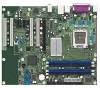
Intel Desktop Board D945PSN Technical Product Specification 1.1.3 Board Layout Figure 1 shows the location of the major components. B D G A C E FH I HH J K L GG FF M EE DD N CC O BB P AA Q Y WV U T Z X - Intel BLKD945PSNLK | Product Specification - Page 13
bus add-in card connector I Back panel connectors J +12V power connector (ATX12V) K Rear chassis fan connector L LGA775 processor socket M Intel 82945P MCH N Processor fan connector O DIMM Channel A sockets [2] P DIMM Channel B sockets [2] Q SCSI LED connector (optional) R Legacy - Intel BLKD945PSNLK | Product Specification - Page 14
Intel Desktop Board D945PSN Technical Product Specification 1.1.4 Block Diagram Figure 2 is a block diagram of the major functional areas. PCI Express x1 Interface PCI Express x1 Slot 1 PCI Express x1 Slot 2 Parallel ATA IDE Connector Parallel ATA IDE Interface LGA775 Processor Socket System - Intel BLKD945PSNLK | Product Specification - Page 15
Board D945PSN Processor data sheets ICH7 addressing Custom splash screens Audio software and utilities LAN software and drivers Supported video modes Visit this World Wide Web site: http://www.intel.com/design/motherbd http://support.intel.com/support/motherboards/desktop http://developer.intel.com - Intel BLKD945PSNLK | Product Specification - Page 16
Intel Desktop Board D945PSN Technical Product Specification 1.4 System Memory The board has four DIMM sockets and support the following memory features: • 1.8 V (only) DDR2 SDRAM DIMMs with gold-plated contacts • Unbuffered, single-sided or double-sided DIMMs with the following restriction: Double- - Intel BLKD945PSNLK | Product Specification - Page 17
Product Description 1.4.1 Memory Configurations The Intel 82945P MCH supports two types of memory organization: • Dual channel (Interleaved) mode. This mode offers the highest throughput for real world applications. Dual channel mode is enabled when - Intel BLKD945PSNLK | Product Specification - Page 18
Intel Desktop Board D945PSN Technical Product Specification 1.4.1.1 Dual Channel (Interleaved) Mode Configurations Figure 4 shows a dual channel configuration using two DIMMs. In this example, the DIMM0 (blue) sockets - Intel BLKD945PSNLK | Product Specification - Page 19
Product Description Figure 6 shows a dual channel configuration using four DIMMs. In this example, the combined capacity of the two DIMMs in Channel A equal the combined capacity of the two DIMMs in Channel B. Also, the DIMMs are matched between DIMM0 and DIMM1 of both channels. 256 MB 512 MB 256 - Intel BLKD945PSNLK | Product Specification - Page 20
Intel Desktop Board D945PSN Technical Product Specification 1.4.1.2 Single Channel (Asymmetric) Mode Configurations NOTE Dual channel (Interleaved) mode configurations provide the highest memory throughput. Figure 7 shows a single channel - Intel BLKD945PSNLK | Product Specification - Page 21
chipset Resources used by the chipset Refer to http://developer.intel.com/ Chapter 2 1.5.1 USB The board supports up to eight USB 2.0 ports, supports UHCI and EHCI, and uses UHCI- and EHCI-compatible drivers. The ICH7 provides the USB controller for all ports. The port arrangement is as follows - Intel BLKD945PSNLK | Product Specification - Page 22
Intel Desktop Board D945PSN Technical Product Specification 1.5.2 IDE Support The board provides five IDE interface connectors: • One parallel ATA IDE connector that supports two devices • Four serial ATA IDE connectors that support one device per connector 1.5.2.1 Parallel ATE IDE Interface The - Intel BLKD945PSNLK | Product Specification - Page 23
about The location of the Serial ATA IDE connectors Refer to Figure 17, page 48 1.5.2.3 Serial ATA RAID (Optional) The optional ICH7-R supports the following RAID (Redundant Array of Independent Drives) levels: • RAID 0 - data striping. Multiple physical drives can be teamed together to create one - Intel BLKD945PSNLK | Product Specification - Page 24
Intel Desktop Board D945PSN Technical Product Specification 1.5.3 Real-Time Clock, CMOS SRAM, and Battery • Automatic discovery, link training, and initialization • Support for Active State Power Management (ASPM) • SMBus 2.0 support • Wake# signal supporting wake events from ACPI S1, S3, S4, or - Intel BLKD945PSNLK | Product Specification - Page 25
information about The location of the parallel port connector Refer to Figure 16, page 47 1.8.3 Diskette Drive Controller The legacy I/O controller supports one diskette drive. Use the BIOS Setup program to configure the diskette drive interface. For information about The location of the diskette - Intel BLKD945PSNLK | Product Specification - Page 26
Intel Desktop Board D945PSN Technical Product Specification 1.9 Audio Subsystem The board supports the Intel® High Definition audio subsystem based on the Sigmatel* 9220 audio codec. The audio subsystem supports the following features: • Advanced jack sense for the back panel audio jacks that - Intel BLKD945PSNLK | Product Specification - Page 27
Intel 82801G I/O Controller Hub (ICH7) • Sigmatel 9220 audio codec • Microphone input that supports a single dynamic, condenser, or electret microphone The back panel audio connectors are configurable through the audio device drivers Controller Hub (ICH7) Intel High Definition Audio Link Sigmatel - Intel BLKD945PSNLK | Product Specification - Page 28
CSMA/CD protocol engine • LAN connect interface that supports the 82562GX • PCI Conventional bus power management ⎯ Supports ACPI technology ⎯ Supports LAN wake capabilities 1.10.1 LAN Subsystem Software LAN software and drivers are available from Intel's World Wide Web site. For information about - Intel BLKD945PSNLK | Product Specification - Page 29
RJ-45 LAN connector with integrated status LEDs. 1.10.2.1 Intel® 82562GX Physical Layer Interface Device The Intel 82562GX provides the following functions: • 10/100 Ethernet LAN connectivity • Full device driver compatibility • Programmable transit threshold • Configuration EEPROM that contains the - Intel BLKD945PSNLK | Product Specification - Page 30
Intel Desktop Board D945PSN Technical Product Specification 1.10.3 Gigabit LAN Subsystem The Gigabit (10/100/1000 Mbits/sec) LAN subsystem includes the Intel 82573V/82574V controller and an RJ-45 LAN connector with integrated status LEDs. 1.10.3.1 Intel® 82573V/82574V Gigabit Ethernet Controller - Intel BLKD945PSNLK | Product Specification - Page 31
diode sensors for direct monitoring of processor temperature and ambient temperature sensing • Power Chassis Intrusion and Detection The board supports a chassis security feature that detects if Monitoring Fan monitoring can be implemented using Intel Desktop Utilities or third-party software. The - Intel BLKD945PSNLK | Product Specification - Page 32
Intel Desktop Board D945PSN Technical Product Specification 1.11.4 Thermal Monitoring Figure 13 shows the location of the sensors and fan Thermal diode, located on processor die Ambient temperature sensor, internal to hardware monitoring and fan control ASIC Processor fan Rear chassis fan Front - Intel BLKD945PSNLK | Product Specification - Page 33
Wake from PS/2 devices ⎯ Power Management Event signal (PME#) wake-up support 1.12.1 ACPI ACPI gives the operating system direct control over the power add-in boards (some add-in boards may require an ACPI-aware driver), video displays, and hard disk drives • Methods for achieving less than - Intel BLKD945PSNLK | Product Specification - Page 34
Intel Desktop Table 8 lists the power states supported by the board along with the state. Full power > 30 W G1 - sleeping state S1 - Processor stopped C1 - stop grant D1, D2, D3 - device specification specific external source. No power to the system. Service can be performed safely. Notes: 1. - Intel BLKD945PSNLK | Product Specification - Page 35
these wake-up events from an ACPI state requires an operating system that provides full ACPI support. In addition, software, drivers, and peripherals must fully support ACPI wake events. 1.12.2 Hardware Support CAUTION Ensure that the power supply provides adequate +5 V standby current if LAN wake - Intel BLKD945PSNLK | Product Specification - Page 36
Intel Desktop Board D945PSN Technical Product Specification NOTE The use of Resume on Ring and Wake from USB technologies from an ACPI state requires an operating system that provides full ACPI support for thermal monitoring The signal names of the processor fan connector The signal names of the - Intel BLKD945PSNLK | Product Specification - Page 37
and can be used to wake the computer. The use of Instantly Available PC technology requires operating system support and PCI 2.3 compliant add-in cards, PCI Express add-in cards, and drivers. 1.12.2.5 Resume on Ring The operation of Resume on Ring can be summarized as follows: • Resumes operation - Intel BLKD945PSNLK | Product Specification - Page 38
Intel Desktop Board D945PSN Technical Product Specification 1.12.2.9 WAKE# Signal Wake-up Support When the WAKE# signal on the PCI Express The optional Trusted Platform Module (TPM) is a component on the desktop board that is specifically designed to enhance platform security above-and-beyond the - Intel BLKD945PSNLK | Product Specification - Page 39
2 Technical Reference What This Chapter Contains 2.1 Introduction ...39 2.2 Memory Resources ...39 2.3 DMA Channels ...41 2.4 Fixed I/O Map...42 2.5 PCI Configuration Space Map 43 2.6 Interrupts ...44 2.7 PCI Conventional Interrupt Routing Map 45 2.8 Connectors...46 2.9 Jumper Block ...57 2.10 - Intel BLKD945PSNLK | Product Specification - Page 40
Intel Desktop Board D945PSN Technical Product Specification • MCH base address registers, internal graphics ranges, PCI Express ports (up to 512 MB) • Memory-mapped I/O that is dynamically allocated - Intel BLKD945PSNLK | Product Specification - Page 41
Technical Reference 2.2.2 Memory Map Table 10 lists the system memory map. Table 10. System Memory Map Address Range (decimal) 1024 K - 4194304 K 960 K - 1024 K 896 K - 960 K 800 K - 896 K Address Range (hex) 100000 - FFFFFFFF F0000 - FFFFF E0000 - EFFFF C8000 - DFFFF 640 K - 800 K 639 K - 640 - Intel BLKD945PSNLK | Product Specification - Page 42
Intel Desktop Board D945PSN Technical Product Specification 2.4 Fixed I/O Map Table 12. I/O Map Address (hex) Size Description 0000 - 00FF 0170 - 0177 01F0 - 01F7 256 bytes 8 bytes 8 bytes Used by the Desktop Board D945PSN. Refer to the ICH7 data sheet for dynamic addressing information. - Intel BLKD945PSNLK | Product Specification - Page 43
00 00 00 00 00 Description Memory controller of Intel 82945P component PCI Express x16 graphics port (Note 1) Intel High Definition Audio Controller PCI Express port 1 PCI 3 PCI Conventional bus connector 4 IEEE-1394a controller (if present) Intel® 82562 10/100 Mbits/sec LAN PLC (if present) PCI - Intel BLKD945PSNLK | Product Specification - Page 44
Intel Desktop Board D945PSN Technical Product Specification 2.6 Interrupts The interrupts can be routed through either the Programmable Interrupt Controller (PIC) or the Advanced Programmable Interrupt Controller (APIC) portion of the ICH7 component. The PIC is supported in Windows 98 SE and - Intel BLKD945PSNLK | Product Specification - Page 45
Technical Reference 2.7 PCI Conventional Interrupt Routing Map This section describes interrupt sharing and how the interrupt signals are connected between the PCI Conventional bus connectors and onboard PCI Conventional devices. The PCI Conventional specification describes how interrupts can be - Intel BLKD945PSNLK | Product Specification - Page 46
Intel Desktop Board D945PSN Technical Product Specification Table 15. PCI Interrupt Routing Map PCI Interrupt Source ICH7 LAN PCI bus connector 1 PCI bus connector 2 PCI bus connector 3 - Intel BLKD945PSNLK | Product Specification - Page 47
Technical Reference 2.8.1 Back Panel Connectors Figure 16 shows the location of the back panel connectors. The back panel connectors are color-coded. The figure legend (Table 16) lists the colors used (when applicable). AC D I E G B F H JK OM17956 Figure 16. Back Panel Connectors Table - Intel BLKD945PSNLK | Product Specification - Page 48
Intel Desktop Board D945PSN Technical Product Specification 2.8.2 Component-side Connectors Figure 17 shows the locations of the component-side connectors. A B C D E F GH I J 4 12 1 9 10 1 3 12 K 34 BB AA - Intel BLKD945PSNLK | Product Specification - Page 49
-in card connector 1 I PCI Express x16 bus add-in card connector J Rear chassis fan connector K +12V power connector (ATX12V) L Processor fan connector M SCSI LED connector (optional) N Power connector O Diskette drive connector P Parallel ATA IDE connector Q Serial ATA connector - Intel BLKD945PSNLK | Product Specification - Page 50
Intel Desktop Board D945PSN Technical Product Specification Table 18. Front Panel Audio Connector Pin Signal Name Pin 1 Port E [Port 1] Left Channel 2 3 Port E [Port 1] Right Channel 4 5 Port F [Port 2] - Intel BLKD945PSNLK | Product Specification - Page 51
Technical Reference Table 22. Processor Fan Connector Pin Signal Name 1 Ground 2 +12 V 3 FAN_TACH 4 FAN_CONTROL 2.8.2.1 Chassis Fan Connectors The board has two standard and one optional chassis fan connectors: • Front chassis - Intel BLKD945PSNLK | Product Specification - Page 52
connector is compatible with 2 x 10 connectors previously used on Intel Desktop boards. The board supports the use of ATX12V power supplies with either 2 x 10 a 2 x 2 connector. This connector provides power directly to the processor voltage regulator and must always be used. Failure to do so will - Intel BLKD945PSNLK | Product Specification - Page 53
pin A40. ⎯ The SMBus data line is connected to pin A41. NOTE The PCI Express x16 connector is configured to support only a PCI Express x1 link when the Intel GMA950 graphics controller is enabled. 2.8.2.4 Auxiliary Front Panel Power/Sleep LED Connector Pins 1 and 3 of this connector duplicate the - Intel BLKD945PSNLK | Product Specification - Page 54
Intel Desktop Board D945PSN Technical Product Specification 2.8.2.5 Front Panel Connector This section describes the functions of the front panel connector. Table 28 lists the signal names of - Intel BLKD945PSNLK | Product Specification - Page 55
Technical Reference 2.8.2.5.2 Reset Switch Connector [Purple] Pins 5 and 7 [Purple] can be connected to a momentary single pole, single throw (SPST) type switch that is normally open. When the switch is closed, the board resets and runs the POST. 2.8.2.5.3 Power/Sleep LED Connector [Green] Pins 2 - Intel BLKD945PSNLK | Product Specification - Page 56
Intel Desktop Board D945PSN Technical Product Specification 2.8.2.6 Front Panel USB Connectors Figure 19 is a connection diagram for the front panel USB connectors. # INTEGRATOR'S NOTES • The +5 V DC power - Intel BLKD945PSNLK | Product Specification - Page 57
the three modes: normal, configure, and recovery. When the jumper is set to configure mode and the computer is powered-up, the BIOS compares the processor version and the microcode version in the BIOS and reports if the two match. 31 J7J3 Figure 21. Location of the Jumper Block OM17958 Table - Intel BLKD945PSNLK | Product Specification - Page 58
Intel Desktop Board D945PSN Technical Product Specification 2.10 Mechanical Considerations 2.10.1 Form Factor The board is designed to fit into an ATX-form-factor chassis. Figure 22 - Intel BLKD945PSNLK | Product Specification - Page 59
specification. NOTE The I/O shield drawings in this document are for reference only. I/O shields compliant with the ATX chassis specification 2.03 are available from Intel. 1.55 REF [0.061] 22.45 [0.884] 7.01 [0.276] Ø 1.00 [0.039] A 0.00 [0.00] 11.81 [0.465] 12.04 [0.474] 162.3 REF [6.390] 20 - Intel BLKD945PSNLK | Product Specification - Page 60
Intel Desktop Board D945PSN Technical Product Specification 2.11 Electrical Considerations 2.11.1 with a 500 mA current draw per USB port. These calculations are not based on specific processor values or memory configurations but are based on the minimum and maximum current draw possible from the - Intel BLKD945PSNLK | Product Specification - Page 61
connectors. Table 33. Fan Connector Current Capability Fan Connector Processor fan Front chassis fan Rear chassis fan Auxiliary fan (optional total amount of standby current required depends on the wake devices supported and manufacturing options. System integrators should refer to the power usage - Intel BLKD945PSNLK | Product Specification - Page 62
the processor and/or voltage regulator or, in some instances, damage to the board. For a list of chassis that have been tested with Intel desktop boards remains solely with the reader. Intel makes no warranties or representations that merely following the instructions presented in this document will - Intel BLKD945PSNLK | Product Specification - Page 63
reach a temperature of up to 85 oC in an open chassis. Figure 25 shows the locations of the localized high temperature zones. A B D C OM17961 Item A B C D Description Processor voltage regulator area Processor Intel 82945P MCH Intel 82801G ICH7 Figure 25. Localized High Temperature Zones 63 - Intel BLKD945PSNLK | Product Specification - Page 64
Intel Desktop Board D945PSN Technical Product Specification Table 34 provides maximum for Components Component Intel Pentium 4 processor Intel 82945P MCH Intel 82801G ICH7 Maximum Case Temperature For processor case temperature, see processor datasheets and processor specification updates 103 - Intel BLKD945PSNLK | Product Specification - Page 65
Technical Reference 2.14 Environmental Table 35 lists the environmental specifications for the board. Table 35. Environmental Specifications Parameter Temperature Non-Operating Operating Shock Unpackaged Packaged Vibration Unpackaged Packaged Specification -40 °C to +70 °C 0 °C to +55 °C 50 g - Intel BLKD945PSNLK | Product Specification - Page 66
Intel Desktop Board D945PSN Technical Product Specification 2.15 Regulatory Compliance This section describes the Desktop Boards' compliance with U.S. and international safety and electromagnetic compatibility (EMC) regulations. 2.15.1 Safety Regulations Table 36 lists the safety regulations that - Intel BLKD945PSNLK | Product Specification - Page 67
and, if not installed and used in accordance with the instructions, may cause harmful interference to radio communications. However, there Declaration of Conformity Statement We, Intel Corporation, declare under our sole responsibility that the product: Intel Desktop Board D945PSN is in conformity - Intel BLKD945PSNLK | Product Specification - Page 68
Intel Desktop Board D945PSN Technical Product Specification Dutch Dit product is in i enlighet med EG-direktiv 89/336/EEC & 73/23/EEC. 2.15.4 Recycling Considerations Intel encourages its customers to recycle its products and their components (e.g., batteries, circuit boards, plastic enclosures - Intel BLKD945PSNLK | Product Specification - Page 69
product certification markings. Table 38. Product Certification Markings Description UL joint US/Canada Recognized Component mark. Includes adjacent UL file number for Intel Desktop Boards: E210882 (component side). Marking FCC Declaration of Conformity logo mark for Class B equipment; includes - Intel BLKD945PSNLK | Product Specification - Page 70
Intel Desktop Board D945PSN Technical Product Specification 70 - Intel BLKD945PSNLK | Product Specification - Page 71
Security Features 77 3.1 Introduction The boards use an Intel BIOS that is stored in the Serial Peripheral Interface Flash the PCI auto-configuration utility, and Plug and Play support. The BIOS displays a message during POST identifying Desktop Board is in configure mode. Section 2.9 on page 57 - Intel BLKD945PSNLK | Product Specification - Page 72
Intel Desktop Board D945PSN Technical Product Specification Table 39 lists the BIOS Setup program menu features. Table 39. BIOS Setup Program Menu Bar Maintenance Main Advanced Security Clears passwords and displays processor information Displays processor support. The IDE interface supports - Intel BLKD945PSNLK | Product Specification - Page 73
specifying manual configuration Desktop processor support, an SMBIOS service-level application running on a non-Plug and Play operating system can obtain the SMBIOS information. 3.5 Legacy USB Support Legacy USB support enables USB devices to be used even when the operating system's USB drivers - Intel BLKD945PSNLK | Product Specification - Page 74
Intel Desktop Board D945PSN Technical Product Specification 5. The operating system loads. While the operating system is loading, USB keyboards and mice are recognized and may be used to configure the operating system. 6. After the operating system loads the USB drivers, all legacy and non-legacy - Intel BLKD945PSNLK | Product Specification - Page 75
boot device, the hard drive second, and the ATAPI CD-ROM third. The fourth device is disabled. 3.7.1 CD-ROM Boot Booting from CD-ROM is supported in compliance to the El Torito bootable CD-ROM format specification. Under the Boot menu in the BIOS Setup program, ATAPI CD-ROM is listed - Intel BLKD945PSNLK | Product Specification - Page 76
Intel Desktop Board D945PSN Technical Product Specification 3.8 Adjusting Boot Speed These factors affect is possible to optimize the boot process to the point where the system boots so quickly that the Intel logo screen (or a custom logo splash screen) will not be seen. Monitors and hard disk drives - Intel BLKD945PSNLK | Product Specification - Page 77
Overview of BIOS Features 3.9 BIOS Security Features The BIOS includes security features that restrict access to the BIOS Setup program and who can boot the computer. A supervisor password and a user password can be set for the BIOS Setup program and for booting the computer, with the following - Intel BLKD945PSNLK | Product Specification - Page 78
Intel Desktop Board D945PSN Technical Product Specification 78 - Intel BLKD945PSNLK | Product Specification - Page 79
Refer to Figure 1, page 12 4.2 BIOS Beep Codes Whenever a recoverable error occurs during POST, the BIOS displays an error message describing the problem (see Table 43). Table 43. Beep Codes Type Memory error Thermal warning Pattern Three long beeps Four alternating beeps: High tone, low tone - Intel BLKD945PSNLK | Product Specification - Page 80
Intel Desktop Board D945PSN Technical Product Specification 4.4 Port 80h POST - CF D0 - DF E0 - FF Category/Subsystem Debug codes: Can be used by any PEIM/driver for debug. Host Processors: 1F is an unrecoverable CPU error. Memory/Chipset: 2F is no memory detected or no useful memory detected - Intel BLKD945PSNLK | Product Specification - Page 81
72 78 79 7A Description of POST Operation Host Processor Power-on initialization of the host processor (Boot Strap Processor) Host processor Cache initialization (including APs) Starting Application processor initialization SMM initialization Chipset Initializing a chipset component Memory Reading - Intel BLKD945PSNLK | Product Specification - Page 82
Intel Desktop Board D945PSN Detecting presence of keyboard Enabling keyboard Clearing keyboard input buffer Instructing keyboard controller to run Self Test (PS2 only) Mouse BDS Trying boot selection y (y=0 to 15) PEI Core Started dispatching PEIMs (emitted on first report of EFI_SW_PC_INIT_BEGIN - Intel BLKD945PSNLK | Product Specification - Page 83
POST Code E7 E8 E9 EA EB EE EF Description of POST Operation DXE Drivers Waiting for user input Checking password Entering BIOS setup TBD - Flash Update Calling service ExitBootServices ( ) has been called F9 EFI runtime service SetVirtualAddressMap ( ) has been called FA EFI runtime service - Intel BLKD945PSNLK | Product Specification - Page 84
Intel Desktop Board D945PSN Technical Product Specification Table 47. Typical Port 80h POST Sequence Configuring memory Testing memory Loading recovery capsule Entered DXE phase Starting Application processor initialization SMM initialization Enumerating PCI busses Allocating resourced to PCI bus
-
 1
1 -
 2
2 -
 3
3 -
 4
4 -
 5
5 -
 6
6 -
 7
7 -
8
-
9
-
10
-
11
-
12
-
13
-
14
-
15
-
16
-
17
-
18
-
19
-
20
-
21
-
22
-
23
-
24
-
25
-
26
-
27
-
28
-
29
-
30
-
31
-
32
-
33
-
34
-
35
-
36
-
37
-
38
-
39
-
40
-
41
-
42
-
43
-
44
-
45
-
46
-
47
-
48
-
49
-
50
-
51
-
52
-
53
-
54
-
55
-
56
-
57
-
58
-
59
-
60
-
61
-
62
-
63
-
64
-
65
-
66
-
67
-
68
-
69
-
70
-
71
-
72
-
73
-
74
-
75
-
76
-
77
-
78
-
79
-
80
-
81
-
82
-
83
-
84
 |
 |

May 2005
Order Number:
D14073-001US
The Intel
®
Desktop Board D945PSN may contain design defects or errors known as errata that may cause the product to deviate from published specifications.
Current
characterized errata are documented in the Intel Desktop Board D945PSN Specification Update.
Intel
®
Desktop Board
D945PSN
Technical Product Specification