Intel BLKD955XCSLKR Product Specification
Intel BLKD955XCSLKR Manual
 |
View all Intel BLKD955XCSLKR manuals
Add to My Manuals
Save this manual to your list of manuals |
Intel BLKD955XCSLKR manual content summary:
- Intel BLKD955XCSLKR | Product Specification - Page 1
July 2005 Order Number: D14066-001US The Intel® Desktop Board D955XCS may contain design defects or errors known as errata that may cause the product to deviate from published specifications. Current characterized errata are documented in the Intel Desktop Board D955XCS Specification Update. - Intel BLKD955XCSLKR | Product Specification - Page 2
supported without further evaluation by Intel. Intel Corporation may or instructions marked "reserved" or "undefined." Intel reserves changes to them. Intel® desktop boards may contain 708-296-9333. Intel, Pentium, and Celeron are registered trademarks of Intel Corporation or its subsidiaries in - Intel BLKD955XCSLKR | Product Specification - Page 3
is intended to provide detailed, technical information about the Intel Desktop Board D955XCS and its components to the vendors, description of the hardware used on the Desktop Board D955XCS A map of the resources of the Desktop Board The features supported by the BIOS Setup program A description - Intel BLKD955XCSLKR | Product Specification - Page 4
Intel Desktop Board D955XCS Technical Product Specification Other Common Notation # (NxnX) of a component, N indicates component type, xn are the relative coordinates of its location on the Desktop Board D955XCS, and X is the instance of the particular part at that general location. For example, - Intel BLKD955XCSLKR | Product Specification - Page 5
Options 11 1.1.3 Board Layout 12 1.1.4 Block Diagram 14 1.2 Online Support ...15 1.3 Processor ...15 1.4 System Memory ...16 1.4.1 Memory Configurations 17 1.5 Intel® 955X Chipset...21 1.5.1 USB ...21 1.5.2 IDE Support 21 1.5.3 Real-Time Clock, CMOS SRAM, and Battery 23 1.6 Discrete - Intel BLKD955XCSLKR | Product Specification - Page 6
Intel Desktop Board D955XCS Technical Product Specification 2 Technical Reference 2.1 Memory Resources ...43 2.1.1 Addressable 80 3.2.2 PCI IDE Support 80 3.3 System Management BIOS (SMBIOS 81 3.4 Legacy USB Support...81 3.5 BIOS Updates ...82 3.5.1 Language Support 82 3.5.2 Custom Splash - Intel BLKD955XCSLKR | Product Specification - Page 7
Intel Rapid BIOS Boot 84 3.8 BIOS Security Features 85 4 Error Messages and Beep Codes 4.1 Speaker ...87 4.2 BIOS Beep Codes...87 4.3 BIOS Error Messages 87 4.4 Port 80h POST Codes 88 Figures 1. Desktop Example of a Processor Heatsink for Omni- 1 13 4. Supported Memory Configurations 16 - Intel BLKD955XCSLKR | Product Specification - Page 8
Intel Desktop Board D955XCS Technical Product Specification 7. Power States and Targeted Front Panel Audio Connector 56 20. Front Chassis Fan and Rear Chassis Fan Connectors 56 21. Processor Fan Connector and Auxiliary Fan Connector 56 22. Chassis Intrusion Connector 57 23. Serial ATA Connectors - Intel BLKD955XCSLKR | Product Specification - Page 9
1 Product Description What This Chapter Contains 1.1 Overview ...10 1.2 Online Support ...15 1.3 Processor ...15 1.4 System Memory ...16 1.5 Intel® 955X Chipset...21 1.6 Discrete Serial ATA Interface (Optional 24 1.7 PCI Express Connectors 24 1.8 Auxiliary Power (AUX PWR) Connector (Optional 25 - Intel BLKD955XCSLKR | Product Specification - Page 10
Audio Legacy I/O Control USB Peripheral Interfaces BIOS Instantly Available PC Technology LAN Support Expansion Capabilities BTX (12.80 inches by 10.50 inches [325.12 millimeters by 266.71 millimeters]) Support for an Intel® Pentium® 4 processor in an LGA775 socket with a 1066 or 800 MHz system bus - Intel BLKD955XCSLKR | Product Specification - Page 11
internal ATAPI CD-ROM drive to the audio mixer Audio Subsystem Intel High Definition Audio subsystem in one of the following configurations: through the BIOS Setup program. Processor power connector One of the following connectors for providing +12 V power to the processor voltage regulator: • 2 - Intel BLKD955XCSLKR | Product Specification - Page 12
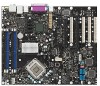
Intel Desktop Board D955XCS Technical Product Specification 1.1.3 Board Layout Figure 1 shows the location of the major components. A B F GH I J K PP C L OO D NN E MM LL KK M N O P Q JJ R II HH GG FF EE DD CC BB AA Z Y X W V U T S Figure 1. Desktop Board Components Table 3 lists - Intel BLKD955XCSLKR | Product Specification - Page 13
) AA Auxiliary PCI Express power connector (optional) BB Speaker CC Intel 82801GR I/O Controller Hub (ICH7-R) DD LGA775 processor socket EE Intel 82955X MCH FF Battery GG Processor power connector HH Processor fan connector II DIMM Channel A sockets [2] JJ DIMM Channel B sockets - Intel BLKD955XCSLKR | Product Specification - Page 14
Intel Desktop Board D955XCS Technical Product Specification 1.1.4 Block Diagram Figure 2 is a block PCI Express x16/x4 Slot SMBus Parallel ATA IDE Connector Parallel ATA IDE Interface LGA775 Processor Socket System Bus (1066/800 MHz) Gigabit Ethernet Controller LAN Connector USB Back Panel - Intel BLKD955XCSLKR | Product Specification - Page 15
Processor data sheets ICH7-R addressing Custom splash screens Audio software and utilities LAN software and drivers Intel® Active Management Technology Visit this World Wide Web site: http://www.intel.com/design/motherbd http://support.intel.com/support/motherboards/desktop http://developer.intel - Intel BLKD955XCSLKR | Product Specification - Page 16
Intel Desktop Board D955XCS Technical Product Specification 1.4 System Memory The board has four DIMM sockets and supports the following memory features: • 1.8 V and 1.9 V DDR2 SDRAM DIMMs • Unbuffered, single-sided or double-sided DIMMs with the following restriction: Double-sided DIMMS with x16 - Intel BLKD955XCSLKR | Product Specification - Page 17
Product Description 1.4.1 Memory Configurations The Intel 82955X MCH supports two types of memory organization: • Dual channel (Interleaved) mode. This mode offers the highest throughput for real world applications. Dual channel mode is enabled when - Intel BLKD955XCSLKR | Product Specification - Page 18
Intel Desktop Board D955XCS Technical Product Specification 1.4.1.1 Dual Channel (Interleaved) Mode Configurations Figure 4 shows a dual channel configuration using two DIMMs. In this example, the DIMM0 (blue) sockets - Intel BLKD955XCSLKR | Product Specification - Page 19
Product Description Figure 6 shows a dual channel configuration using four DIMMs. In this example, the combined capacity of the two DIMMs in Channel A equal the combined capacity of the two DIMMs in Channel B. Also, the DIMMs are matched between DIMM0 and DIMM1 of both channels. 256 MB 512 MB 256 - Intel BLKD955XCSLKR | Product Specification - Page 20
Intel Desktop Board D955XCS Technical Product Specification 1.4.1.2 Single Channel (Asymmetric) Mode Configurations NOTE Dual channel (Interleaved) mode configurations provide the highest memory throughput. Figure 7 shows a single channel - Intel BLKD955XCSLKR | Product Specification - Page 21
intel.com/ Chapter 2 1.5.1 USB The board supports up to eight USB 2.0 ports, supports UHCI and EHCI, and uses UHCI- and EHCI-compatible drivers interface supports the following modes: • Programmed I/O (PIO): processor controls data transfer. • 8237-style DMA: DMA offloads the processor, supporting - Intel BLKD955XCSLKR | Product Specification - Page 22
Intel Desktop Board D955XCS Technical Product Specification • ATA-100: DMA protocol on IDE point-to-point interface is used for host to device connections, unlike Parallel ATA IDE which supports a master/slave configuration and two devices per channel. For compatibility, the underlying Serial ATA - Intel BLKD955XCSLKR | Product Specification - Page 23
Product Description 1.5.2.3 Serial ATA RAID The ICH7-R supports the following RAID (Redundant Array of Independent Drives) levels: • RAID 0 - data striping. Multiple physical drives can be teamed together to create one logical drive. As - Intel BLKD955XCSLKR | Product Specification - Page 24
Intel Desktop Board D955XCS Technical Product Specification 1.6 Discrete Serial ATA Interface (Optional) As a manufacturing option, the board provides a Silicon Image Sil 3114 Serial ATA (SATA) controller and four connectors (that support The discrete SATA interface supports the following RAID - Intel BLKD955XCSLKR | Product Specification - Page 25
) The optional IEEE-1394 interface addresses interconnection of both computer peripherals and consumer electronics with these features: • IEEE-1394a and IEEE-1394b operation • Support for up to 63 peer-to-peer devices • Operation ranging from 100 Mbits/sec to 800 Mbits/sec (depending on cable type - Intel BLKD955XCSLKR | Product Specification - Page 26
Intel Desktop Board D955XCS Technical Product Specification For information about The location of connector Refer to Figure 18, page 53 1.10.3 Diskette Drive Controller The legacy I/O controller supports one diskette drive. Use the BIOS Setup program to configure the diskette drive interface. For - Intel BLKD955XCSLKR | Product Specification - Page 27
Figure 18, page 53 1.11 Audio Subsystem The board supports the Intel High Definition audio subsystem based on the Sigmatel 9223 or the software and drivers are available from Intel's World Wide Web site. For information about Refer to Obtaining audio software and drivers Section 1.2, page - Intel BLKD955XCSLKR | Product Specification - Page 28
includes the following: • Intel 82801GR I/O Controller Hub (ICH7-R) • Sigmatel 9223 audio codec • Microphone input that supports a single dynamic, condenser, or electret microphone The back panel audio connectors are configurable through the audio device drivers. The available configurable audio - Intel BLKD955XCSLKR | Product Specification - Page 29
Product Description Figure 10 is a block diagram of the 8-channel (7.1) audio subsystem. 82801GR I/O Controller Hub (ICH7-R) Intel High Definition Audio Link Sigmatel 9223 Audio Codec Front Panel Mic In Front Panel Line Out Mic In/Retasking Jack Side Surround L-R/Line In/Retasking - Intel BLKD955XCSLKR | Product Specification - Page 30
includes the following: • Intel 82801GR I/O Controller Hub (ICH7-R) • Sigmatel 9220 audio codec • Microphone input that supports a single dynamic, condenser, or electret microphone The back panel audio connectors are configurable through the audio device drivers. The available configurable audio - Intel BLKD955XCSLKR | Product Specification - Page 31
LEDs. 1.12.1 Intel® 82573E/82573V Gigabit Ethernet Controller The Intel 82573E/82573V Gigabit Ethernet Controller supports the following features: • Full device driver compatibility • PCI Express Power Management Support The 82573E Gigabit Ethernet Controller also supports Alert Standard Format - Intel BLKD955XCSLKR | Product Specification - Page 32
Intel Desktop Board D955XCS Technical Product Specification 1.12.3 Alert Standard Format (ASF) Support (Optional) The board provides the following ASF support for PCI Express x1 bus add-in LAN cards and PCI Conventional bus add-in LAN cards installed in PCI Conventional bus slot 2: • Monitoring of - Intel BLKD955XCSLKR | Product Specification - Page 33
diagnose problems quickly to reduce end-user downtime • Protecting the enterprise against malicious software attacks: ⎯ Intel AMT helps ⎯ TCP/IP ⎯ HTTP web GUI ⎯ XML/SOAP API • Remote troubleshooting and recovery that can significantly reduce desk-side visits and potentially increasing efficiency - Intel BLKD955XCSLKR | Product Specification - Page 34
Intel Desktop Board D955XCS Technical Product Specification 1.12.5 LAN Subsystem Software LAN software and drivers are available from Intel's World Wide Web site. For information about Obtaining LAN software and drivers for direct monitoring of processor temperature and ambient temperature sensing - Intel BLKD955XCSLKR | Product Specification - Page 35
OM18045 Item A B C D E F G Description Remote ambient temperature sensor Thermal diode, located on processor die Ambient temperature sensor, internal to hardware monitoring and fan control ASIC Processor fan connector Rear chassis fan connector Front chassis fan connector Auxiliary fan connector - Intel BLKD955XCSLKR | Product Specification - Page 36
Desktop Board. For information about The functions of the fan connectors Refer to Section 1.14.2.2, page 40 1.13.4 Chassis Intrusion and Detection The board supports -in boards (some add-in boards may require an ACPI-aware driver), video displays, and hard disk drives • Methods for achieving less - Intel BLKD955XCSLKR | Product Specification - Page 37
Product Description Table 6 lists the system states based on how long the power switch is pressed, depending on how ACPI is configured with an ACPI-aware operating system. Table 6. Effects of Pressing the Power Switch If the system is in this state... Off (ACPI G2/G5 - Soft off) On (ACPI G0 - - Intel BLKD955XCSLKR | Product Specification - Page 38
Intel Desktop Board D955XCS Technical Product Specification Table 7 lists the power states supported saved. Cold boot is required. No power to the system. Processor States C0 - working C1 - stop grant No power No external source. No power to the system. Service can be performed safely. Notes: 1. - Intel BLKD955XCSLKR | Product Specification - Page 39
these wake-up events from an ACPI state requires an operating system that provides full ACPI support. In addition, software, drivers, and peripherals must fully support ACPI wake events. 1.14.2 Hardware Support CAUTION Ensure that the power supply provides adequate +5 V standby current if LAN wake - Intel BLKD955XCSLKR | Product Specification - Page 40
Intel Desktop Board D955XCS Technical Product Specification NOTE The use of Resume on Ring and Wake from USB technologies from an ACPI state requires an operating system that provides full ACPI support. 1.14.2.1 Power Connector When an ACPI-enabled system receives the appropriate command, the - Intel BLKD955XCSLKR | Product Specification - Page 41
and can be used to wake the computer. The use of Instantly Available PC technology requires operating system support and PCI 2.3 compliant add-in cards, PCI Express add-in cards, and drivers. 1.14.2.5 Resume on Ring The operation of Resume on Ring can be summarized as follows: • Resumes operation - Intel BLKD955XCSLKR | Product Specification - Page 42
Intel Desktop Board D955XCS Technical Product Specification 1.14.2.10 +5 V Standby Power Indicator LED Module (Optional) The optional Trusted Platform Module (TPM) is a component on the desktop board that is specifically designed to enhance platform security above-and-beyond the capabilities of - Intel BLKD955XCSLKR | Product Specification - Page 43
2 Technical Reference What This Chapter Contains 2.1 Memory Resources ...43 2.2 DMA Channels ...45 2.3 Fixed I/O Map...46 2.4 PCI Configuration Space Map 47 2.5 Interrupts ...48 2.6 PCI Conventional Interrupt Routing Map 49 2.7 Connectors...51 2.8 Jumper Block ...65 2.9 Mechanical Considerations - Intel BLKD955XCSLKR | Product Specification - Page 44
Intel Desktop Board D955XCS Technical Product Specification 8 GB Top of System Address Space FLASH APIC Reserved Upper 4 GB of address space ~20 MB PCI Memory Range contains - Intel BLKD955XCSLKR | Product Specification - Page 45
Technical Reference 2.1.2 Memory Map Table 9 lists the system memory map. Table 9. System Memory Map Address Range (decimal) 1024 K - 8388608 K 960 K - 1024 K 896 K - 960 K 800 K - 896 K Address Range (hex) 100000 - 1FFFFFFFF F0000 - FFFFF E0000 - EFFFF C8000 - DFFFF 640 K - 800 K 639 K - 640 K - Intel BLKD955XCSLKR | Product Specification - Page 46
Intel Desktop Board D955XCS Technical Product Specification 2.3 Fixed I/O Map Table 11. I/O Map bytes 8 bytes 4 bytes 1 byte 4 bytes 8 bytes 8 bytes Description Used by the Desktop Board D955XCS. Refer to the ICH7-R data sheet for dynamic addressing information. Secondary Parallel ATA IDE - Intel BLKD955XCSLKR | Product Specification - Page 47
02 03 00 01 02 03 07 00 00 01 02 03 00 00 00 00 00 00 Description Memory controller of Intel 82955X component PCI Express x16 graphics port Intel High Definition Audio Controller PCI Express port 1 PCI Express port 2 PCI Express port 3 PCI Express port 4 USB UHCI controller 1 USB UHCI - Intel BLKD955XCSLKR | Product Specification - Page 48
Intel Desktop Board D955XCS Technical Product Specification 2.5 Interrupts The interrupts can be routed through either the Programmable Interrupt Controller (PIC) or the Advanced Programmable Interrupt Controller (APIC) portion of the ICH7-R component. The PIC is supported in Windows 98 SE and - Intel BLKD955XCSLKR | Product Specification - Page 49
Technical Reference 2.6 PCI Conventional Interrupt Routing Map This section describes interrupt sharing and how the interrupt signals are connected between the PCI Conventional bus connectors and onboard PCI Conventional devices. The PCI Conventional specification describes how interrupts can be - Intel BLKD955XCSLKR | Product Specification - Page 50
Intel Desktop Board D955XCS Technical Product Specification Table 14. PCI Interrupt Routing Map PCI Interrupt Source IEEE-1394a/b controller PCI bus connector 1 PCI bus connector 2 PCI bus - Intel BLKD955XCSLKR | Product Specification - Page 51
Technical Reference 2.7 Connectors CAUTION Only the following connectors have overcurrent protection: back panel USB, front panel USB, and PS/2. The other internal connectors are not overcurrent protected and should connect only to devices inside the computer's chassis, such as fans and internal - Intel BLKD955XCSLKR | Product Specification - Page 52
Intel Desktop Board D955XCS Technical Product Specification 2.7.1.1 Back Panel Connectors For 8-Channel (7.1) Audio Subsystem Figure 17 shows the location of the back panel connectors for boards equipped - Intel BLKD955XCSLKR | Product Specification - Page 53
Technical Reference 2.7.1.2 Back Panel Connectors For 6-Channel (5.1) Audio Subsystem Figure 18 shows the location of the back panel connectors for boards equipped with the 6-channel (5.1) audio subsystem. The back panel connectors are color-coded. The figure legend (Table 16) lists the colors used - Intel BLKD955XCSLKR | Product Specification - Page 54
Intel Desktop Board D955XCS Technical Product Specification 2.7.2 Component-side Connectors Figure 19 shows the locations of the component-side connectors. A B CDE FGH I J K L M N O P Q 12 24 12 4 1 1 1 13 3 39 - Intel BLKD955XCSLKR | Product Specification - Page 55
connector AA Front chassis fan connector BB Diskette drive connector CC Auxiliary front panel power LED connector DD Auxiliary PCI Express power connector (optional) EE Processor power connector FF Processor fan connector GG Rear chassis fan connector 55 - Intel BLKD955XCSLKR | Product Specification - Page 56
Intel Desktop Board D955XCS Technical Product Specification Table 18. ATAPI CD-ROM Sense return (jack detection) Key Port F [Port 2] Sense return (jack detection) Table 21. Processor Fan Connector and Auxiliary Fan Connector Pin Signal Name 1 Ground 2 +12 V 3 FAN_TACH 4 FAN_CONTROL - Intel BLKD955XCSLKR | Product Specification - Page 57
Technical Reference Table 22. Chassis Intrusion Connector Pin Signal Name 1 Intruder 2 Ground Table 23. Serial ATA Connectors Pin Signal Name 1 Ground 2 TXP 3 TXN 4 Ground 5 RXN 6 RXP 7 Ground Table 24. Auxiliary Power (AUX PWR) Output Connector (Optional) Pin Signal Name - Intel BLKD955XCSLKR | Product Specification - Page 58
Intel Desktop Board D955XCS Technical Product Specification 2.7.2.1 Power Supply Connectors The board has three power supply connectors: • Main power - a 2 x 12 connector. The board requires a power supply with a 2 x 12 main power cable. • Processor power - This connector provides power directly to - Intel BLKD955XCSLKR | Product Specification - Page 59
10 +12 V 22 11 +12 V 23 12 2 x 12 connector detect 24 Table 26. Processor Power Connector (2 x 4 Pin) Pin Signal Name Pin 1 Ground 5 2 Ground 6 3 Ground 7 4 Ground 8 Table 27. Processor Power Connector (2 x 2 Pin) Pin Signal Name Pin 1 Ground 2 2 Ground 4 Table 28 - Intel BLKD955XCSLKR | Product Specification - Page 60
Intel Desktop Board D955XCS Technical Product Specification 2.7.2.2 Add-in Card Connectors The board has the following add-in card connectors: • PCI Express x16; one connector supporting simultaneous transfers up to 8 GBytes/sec • Secondary PCI Express x16/x4 bus; one connector supporting - Intel BLKD955XCSLKR | Product Specification - Page 61
Technical Reference 2.7.2.4 Front Panel Connector This section describes the functions of the front panel connector. Table 30 lists the signal names of the front panel connector. Figure 20 is a connection diagram for the front panel connector. Table 30. Front Panel Connector Pin Signal In/Out - Intel BLKD955XCSLKR | Product Specification - Page 62
Intel Desktop Board D955XCS Technical Product Specification 2.7.2.4.1 Hard Drive Activity LED Connector [Yellow] Pins 1 and 3 [Yellow] can be connected to an LED to provide a visual indicator that - Intel BLKD955XCSLKR | Product Specification - Page 63
Technical Reference 2.7.2.5 Front Panel USB Connectors Figure 21 is a connection diagram for the front panel USB connectors. # INTEGRATOR'S NOTES • The +5 V DC power on the USB connector is fused. • Pins 1, 3, 5, and 7 comprise one USB port. • Pins 2, 4, 6, and 8 comprise one USB port. • Use only a - Intel BLKD955XCSLKR | Product Specification - Page 64
Intel Desktop Board D955XCS Technical Product Specification 2.7.2.6 Front Panel IEEE 1394a/b Connectors (Optional) Figure 22 is a connection diagram for the IEEE 1394a/b connectors. TPA+ 1 2 TPA− Ground TPB+ 3 4 - Intel BLKD955XCSLKR | Product Specification - Page 65
for the three modes: normal, configure, and recovery. When the jumper is set to configure mode and the computer is poweredup, the BIOS compares the processor version and the microcode version in the BIOS and reports if the two match. 1 3 J3F3 Figure 23. Location of the Jumper Block OM18047 Table - Intel BLKD955XCSLKR | Product Specification - Page 66
Intel Desktop Board D955XCS Technical Product Specification 2.9 Mechanical Considerations 2.9.1 Form Factor The board is designed to fit into a BTX-form-factor chassis. Figure 24 illustrates the mechanical - Intel BLKD955XCSLKR | Product Specification - Page 67
specification. NOTE The I/O shield drawings in this document are for reference only. I/O shields compliant with the BTX specification are available from Intel. 1.55 REF [0.061] 172.9 REF [6.808] 13.0 TYP [0.512] 169.9 ± 0.12 [6.692 ± 0.005] 1.6 ± 0.12 [0.063 ± 0.005] 9.65 [0.38] Ø 1.00 [0.039 - Intel BLKD955XCSLKR | Product Specification - Page 68
Intel Desktop Board D955XCS Technical Product Specification 1.55 REF [0.061] 9.65 [0.38] Ø 1.00 [0.039] A 0.00 [0.00] 9.18 [0.36] 9.40 [0.37] 172.9 REF [6.808] 13.0 TYP [0.512] 169.9 ± 0. - Intel BLKD955XCSLKR | Product Specification - Page 69
draw per USB port. These calculations are not based on specific processor values or memory configurations but are based on the minimum and maximum add-in board. The total +5 V current draw for add-in boards for the desktop board is as follows: a fully loaded board (all six expansion slots and the PCI - Intel BLKD955XCSLKR | Product Specification - Page 70
Intel Desktop Board D955XCS Technical Product Specification 2.10.3 Fan Connector Current Capability CAUTION The processor fan must be connected to the processor fan connector, not to a chassis fan connector. Connecting the processor on the wake devices supported and manufacturing options. System - Intel BLKD955XCSLKR | Product Specification - Page 71
the processor voltage regulator area cool. This is particularly important when using liquid cooling. All responsibility for determining the adequacy of any thermal or system design remains solely with the reader. Intel makes no warranties or representations that merely following the instructions - Intel BLKD955XCSLKR | Product Specification - Page 72
Intel Desktop Board D955XCS Technical Product Specification AB C Item A B C D E E D Description Intel 82955X MCH Intel 82801GR ICH7-R 1.5 V core and front side bus voltage regulator areas Processor Processor voltage regulator area OM18049 Figure 28. Localized High Temperature Zones CAUTION - Intel BLKD955XCSLKR | Product Specification - Page 73
monitoring application software, an alert point of 110 oC is recommended as a starting point for the processor voltage regulator area. For information about Intel Pentium 4 processor datasheets and specification updates Refer to Section 1.2, page 15 2.12 Reliability The Mean Time Between Failures - Intel BLKD955XCSLKR | Product Specification - Page 74
Intel Desktop Board D955XCS Technical Product Specification 2.13 Environmental Table 37 lists the environmental specifications for the board. Table 37. Environmental Specifications Parameter Temperature Non-Operating Operating - Intel BLKD955XCSLKR | Product Specification - Page 75
U.S. and international safety and electromagnetic compatibility (EMC) regulations. 2.14.1 Safety Regulations Table 38 lists the safety regulations the Desktop Board D955XCS complies with when correctly installed in a compatible host system. Table 38. Safety Regulations Regulation UL 60950-1:2003 - Intel BLKD955XCSLKR | Product Specification - Page 76
and, if not installed and used in accordance with the instructions, may cause harmful interference to radio communications. However, there Declaration of Conformity Statement We, Intel Corporation, declare under our sole responsibility that the product: Intel® Desktop Board D955XCS is in conformity - Intel BLKD955XCSLKR | Product Specification - Page 77
/EEC & 73/23/EEC. Svenska Denna produkt har tillverkats i enlighet med EG-direktiv 89/336/EEC & 73/23/EEC. 2.14.4 Recycling Considerations Intel encourages its customers to recycle its products and their components (e.g., batteries, circuit boards, plastic enclosures, etc.) whenever possible. In the - Intel BLKD955XCSLKR | Product Specification - Page 78
product certification markings. Table 40. Product Certification Markings Description UL joint US/Canada Recognized Component mark. Includes adjacent UL file number for Intel Desktop Boards: E210882 (component side). Marking FCC Declaration of Conformity logo mark for Class B equipment; includes - Intel BLKD955XCSLKR | Product Specification - Page 79
3.1 Introduction ...79 3.2 Resource Configuration 80 3.3 System Management BIOS (SMBIOS 81 3.4 Legacy USB Support...81 3.5 BIOS Updates ...82 3.6 Boot Options ...83 3.7 Fast Booting Systems with Intel® Rapid BIOS Boot 84 3.8 BIOS Security Features 85 3.1 Introduction The BIOS is stored in - Intel BLKD955XCSLKR | Product Specification - Page 80
Intel Desktop Board D955XCS Technical Product Specification Table 41 lists the BIOS Setup program menu features. Table 41. BIOS Setup Program Menu Bar Maintenance Main Advanced Security Clears passwords and displays processor information Displays processor support. The IDE interface supports - Intel BLKD955XCSLKR | Product Specification - Page 81
a Desktop Management and processor clock frequency support, an SMBIOS service-level application running on a non-Plug and Play operating system can obtain the SMBIOS information. 3.4 Legacy USB Support Legacy USB support enables USB devices to be used even when the operating system's USB drivers - Intel BLKD955XCSLKR | Product Specification - Page 82
accidentally installing an incompatible BIOS. NOTE Review the instructions distributed with the upgrade utility before attempting a BIOS update. For information about The Intel World Wide Web site Refer to Section 1.2, page 15 3.5.1 Language Support The BIOS Setup program and help messages - Intel BLKD955XCSLKR | Product Specification - Page 83
boot device, the hard drive second, and the ATAPI CD-ROM third. The fourth device is disabled. 3.6.1 CD-ROM Boot Booting from CD-ROM is supported in compliance to the El Torito bootable CD-ROM format specification. Under the Boot menu in the BIOS Setup program, ATAPI CD-ROM is listed - Intel BLKD955XCSLKR | Product Specification - Page 84
Intel Desktop Board D955XCS Technical Product Specification 3.7 Fast Booting Systems with Intel® Rapid BIOS Boot These factors affect the amount of time for a system to complete boot process: • Selecting and configuring peripherals properly • Using an optimized BIOS, such as the Intel® Rapid BIOS - Intel BLKD955XCSLKR | Product Specification - Page 85
Overview of BIOS Features 3.8 BIOS Security Features The BIOS includes security features that restrict access to the BIOS Setup program and who can boot the computer. A supervisor password and a user password can be set for the BIOS Setup program and for booting the computer, with the following - Intel BLKD955XCSLKR | Product Specification - Page 86
Intel Desktop Board D955XCS Technical Product Specification 86 - Intel BLKD955XCSLKR | Product Specification - Page 87
Refer to Figure 1, page 12 4.2 BIOS Beep Codes Whenever a recoverable error occurs during POST, the BIOS displays an error message describing the problem (see Table 45). Table 45. Beep Codes Type Memory error Thermal warning Pattern Three long beeps Four alternating beeps: High tone, low tone - Intel BLKD955XCSLKR | Product Specification - Page 88
Intel Desktop Board D955XCS Technical Product Specification 4.4 Port 80h POST - CF D0 - DF E0 - FF Category/Subsystem Debug codes: Can be used by any PEIM/driver for debug. Host Processors: 1F is an unrecoverable CPU error. Memory/Chipset: 2F is no memory detected or no useful memory detected - Intel BLKD955XCSLKR | Product Specification - Page 89
72 78 79 7A Description of POST Operation Host Processor Power-on initialization of the host processor (Boot Strap Processor) Host processor Cache initialization (including APs) Starting Application processor initialization SMM initialization Chipset Initializing a chipset component Memory Reading - Intel BLKD955XCSLKR | Product Specification - Page 90
Intel Desktop Board D955XCS Technical of the keyboard Enabling the keyboard Clearing keyboard input buffer Instructing keyboard controller to run Self Test (PS2 only) Mouse BDS Trying boot selection y (y=0 to 15) PEI Core Started dispatching PEIMs (emitted on first report of EFI_SW_PC_INIT_BEGIN - Intel BLKD955XCSLKR | Product Specification - Page 91
POST Code E7 E8 E9 EA EB EE EF Description of POST Operation DXE Drivers Waiting for user input Checking password Entering BIOS setup TBD - Flash Update Calling service ExitBootServices ( ) has been called F9 EFI runtime service SetVirtualAddressMap ( ) has been called FA EFI runtime service - Intel BLKD955XCSLKR | Product Specification - Page 92
Intel Desktop Board D955XCS Technical Product Specification Table 49. Typical Port 80h POST Sequence Configuring memory Testing memory Loading recovery capsule Entered DXE phase Starting Application processor initialization SMM initialization Enumerating PCI busses Allocating resourced to PCI bus
-
 1
1 -
 2
2 -
 3
3 -
 4
4 -
 5
5 -
 6
6 -
 7
7 -
8
-
9
-
10
-
11
-
12
-
13
-
14
-
15
-
16
-
17
-
18
-
19
-
20
-
21
-
22
-
23
-
24
-
25
-
26
-
27
-
28
-
29
-
30
-
31
-
32
-
33
-
34
-
35
-
36
-
37
-
38
-
39
-
40
-
41
-
42
-
43
-
44
-
45
-
46
-
47
-
48
-
49
-
50
-
51
-
52
-
53
-
54
-
55
-
56
-
57
-
58
-
59
-
60
-
61
-
62
-
63
-
64
-
65
-
66
-
67
-
68
-
69
-
70
-
71
-
72
-
73
-
74
-
75
-
76
-
77
-
78
-
79
-
80
-
81
-
82
-
83
-
84
-
85
-
86
-
87
-
88
-
89
-
90
-
91
-
92
 |
 |

July 2005
Order Number:
D14066-001US
The Intel
®
Desktop Board D955XCS may contain design defects or errors known as errata that may cause the product to deviate from published specifications.
Current
characterized errata are documented in the Intel Desktop Board D955XCS Specification Update.
Intel
®
Desktop Board
D955XCS
Technical Product Specification