Intel BLKDG33BUC Product Specification
Intel BLKDG33BUC Manual
 |
View all Intel BLKDG33BUC manuals
Add to My Manuals
Save this manual to your list of manuals |
Intel BLKDG33BUC manual content summary:
- Intel BLKDG33BUC | Product Specification - Page 1
May 2007 Order Number: D88104-001US The Intel® Desktop Board DG33BU may contain design defects or errors known as errata that may cause the product to deviate from published specifications. Current characterized errata are documented in the Intel Desktop Board DG33BU Specification Update. - Intel BLKDG33BUC | Product Specification - Page 2
specification applies to only the standard Intel® Desktop Board DG33BU with BIOS identifier DPP3510A.86A. Changes to this specification will be published in the Intel Desktop Board DG33BU Specification Update Intel, the Intel logo, Pentium, Core, and Celeron are registered trademarks of Intel - Intel BLKDG33BUC | Product Specification - Page 3
board The features supported by the BIOS Setup program A description of the BIOS error messages, beep codes, and POST codes Regulatory compliance and battery disposal information Typographical Conventions This section contains information about the conventions used in this specification. Not all of - Intel BLKDG33BUC | Product Specification - Page 4
Intel Desktop Board DG33BU Technical Product Specification Other Common Notation # GB GB/sec Gbit KB Kbit kbits/sec MB MB/sec Mbit Mbit/sec xxh x.x V * Used after a signal name to identify an - Intel BLKDG33BUC | Product Specification - Page 5
12 1.1.3 Block Diagram 14 1.2 Legacy Considerations 15 1.3 Online Support 15 1.4 Processor 15 1.5 System Memory 16 1.5.1 Memory Configurations 17 1.6 Intel® G33 Express Chipset 19 1.6.1 Intel G33 Graphics Subsystem 19 1.6.2 Intel® Viiv™ Processor Technology 21 1.6.3 USB 21 1.6.4 Serial ATA - Intel BLKDG33BUC | Product Specification - Page 6
Features 3.1 Introduction 57 3.2 BIOS Flash Memory Organization 58 3.3 Resource Configuration 58 3.3.1 PCI Autoconfiguration 58 3.3.2 PCI IDE Support 59 3.4 System Management BIOS (SMBIOS 59 3.5 Legacy USB Support 60 3.6 BIOS Updates 61 3.6.1 Language Support 61 3.6.2 Custom Splash Screen - Intel BLKDG33BUC | Product Specification - Page 7
Summary 10 2. Board Components Shown in Figure 1 13 3. Supported Memory Configurations 16 4. Audio Jack Support 24 5. LAN Connector LED States 27 6. Effects of Pressing the /Sleep LED Header 45 18. Processor Core Power Connector 46 19. Main Power Connector 46 20. Front Panel Header 47 vii - Intel BLKDG33BUC | Product Specification - Page 8
Intel Desktop Board DG33BU Technical Product Specification 21. States for a One-Color Power LED 48 22. States for a Two-Color Power LED 48 23. Auxiliary Front Panel Power LED Header 48 24. BIOS Setup Configuration Jumper Settings 50 25. Recommended Power Supply Current Values 52 26. Fan Header - Intel BLKDG33BUC | Product Specification - Page 9
1 Product Description What This Chapter Contains 1.1 Overview 10 1.2 Legacy Considerations 15 1.3 Online Support 15 1.4 Processor 15 1.5 System Memory 16 1.6 Intel® G33 Express Chipset 19 1.7 Parallel IDE Controller 22 1.8 Real-Time Clock Subsystem 23 1.9 Legacy I/O Controller 23 1.10 Audio - Intel BLKDG33BUC | Product Specification - Page 10
]) Processor Memory Chipset Video Support for the following: • Intel® Core™2 Quad processor in an LGA775 socket with a 1066 MHz system bus • Intel® Core™2 Duo processor in an LGA775 socket with a 1066 or 800 MHz system bus • Intel® Pentium® Dual-Core processor in an LGA775 socket with an - Intel BLKDG33BUC | Product Specification - Page 11
bus connectors • One PCI Express x1 bus add-in card connector • One PCI Express x16 bus add-in card connector • Intel® Quiet System Technology implemented through the Intel® Management Engine in ICH9DH • Voltage sense to detect out of range power supply voltages • Thermal sense to detect out of - Intel BLKDG33BUC | Product Specification - Page 12
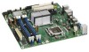
Intel Desktop Board DG33BU Technical Product Specification 1.1.2 Board Layout Figure 1 shows the location of the major components. Figure 1. Major Board Components Table 2 lists the components identified in Figure 1. 12 - Intel BLKDG33BUC | Product Specification - Page 13
x16 connector G Back panel connectors H Processor core power connector (2 X 2) I Rear chassis fan header J LGA775 processor socket K Intel 82G33 GMCH L Processor fan header M DIMM Channel A sockets N Serial port header O DIMM Channel B sockets P Main Power connector (2 X 12 - Intel BLKDG33BUC | Product Specification - Page 14
Intel Desktop Board DG33BU Technical Product Specification 1.1.3 Block Diagram Figure 2 is a block diagram of the major functional areas. Figure 2. Block Diagram 14 - Intel BLKDG33BUC | Product Specification - Page 15
downloadcenter.intel.com http://support.intel.com/support/motherboards/desktop/sb/CS025414.htm 1.4 Processor The board is designed to support the following processors: • Intel Core 2 Quad processor in an LGA775 socket with a 1066 MHz system bus • Intel Core 2 Duo processor in an LGA775 socket with - Intel BLKDG33BUC | Product Specification - Page 16
Intel Desktop Board DG33BU Technical Product Specification # INTEGRATOR'S NOTE Use only ATX12V-compliant power supplies. For information about Power supply connectors Refer to Section 2.2.2.4, page 46 1.5 System Memory The board has four DIMM sockets and supports the following memory features: • - Intel BLKDG33BUC | Product Specification - Page 17
mode results in multiple zones of dual and single channel operation across the whole of DRAM memory. To use flex mode, it is necessary to populate both channels. For information about... Memory Configuration Examples Refer to: http://www.intel.com/support/motherboards/desktop/sb/cs011965.htm 17 - Intel BLKDG33BUC | Product Specification - Page 18
Intel Desktop Board DG33BU Technical Product Specification Figure 3 illustrates the memory channel and DIMM configuration. NOTE The DIMM 0 sockets of both channels are blue. The DIMM 1 sockets of both channels are black. Figure 3. Memory Channel Configuration and DIMM Configuration # INTEGRATOR'S - Intel BLKDG33BUC | Product Specification - Page 19
ICH9DH is a centralized controller for the board's I/O paths. The chipset supports the following features: • Onboard Graphics • Dynamic Video Memory Technology • USB • Serial ATA • Parallel IDE For information about The Intel G33 Express chipset Resources used by the chipset Refer to http://www - Intel BLKDG33BUC | Product Specification - Page 20
Intel Desktop Board DG33BU Technical Product Specification • Video ⎯ Software DVD at 30 fps full screen ⎯ DVMT support up to 256 MB • Display ⎯ Supports analog displays up to 2048 x 1536 at 75 Hz refresh (QXGA) ⎯ Dual independent display support ⎯ DDC2B compliant interface with Advanced Digital - Intel BLKDG33BUC | Product Specification - Page 21
(when used with the HD Audio Link) 1.6.2 Intel® Viiv™ Processor Technology This Intel desktop board supports Intel Viiv processor technology. To be eligible for the Intel Viiv processor technology brand, a system must meet certain hardware and software requirements. To get the list of requirements - Intel BLKDG33BUC | Product Specification - Page 22
Intel Desktop Board DG33BU Technical Product Specification supporting host and target throttling and transfer rates of up to 66 MB/sec. ATA-66 protocol is similar to Ultra DMA and is device driver also supports ATAPI devices (such as CD-ROM drives) and ATA devices. The BIOS supports Logical Block - Intel BLKDG33BUC | Product Specification - Page 23
(CR2032) powers the real-time clock and CMOS memory. When the computer is not plugged into a wall socket, the battery has an estimated life of three side of the board. The serial port supports data transfers at speeds up to 115.2 kbits/sec with BIOS support. For information about The location of - Intel BLKDG33BUC | Product Specification - Page 24
Intel Desktop Board DG33BU Technical Product Specification 1.9.3 PS/2 Keyboard and Mouse Interface The PS/2 keyboard and mouse connectors are located on the back panel. NOTE The keyboard is supported in the bottom PS/2 connector and the mouse is supported in the top PS/2 connector. Power to the - Intel BLKDG33BUC | Product Specification - Page 25
Software Audio software and drivers are available from Intel's World Wide Web site. For information about Obtaining audio software and drivers supported for both the front and back panel microphone connectors. The front/back panel audio connectors are configurable through the audio device drivers. - Intel BLKDG33BUC | Product Specification - Page 26
⎯ LAN wake capabilities • LAN subsystem software For information about LAN software and drivers Refer to http://downloadcenter.intel.com 1.11.1 Intel® 82566DC Gigabit Ethernet Controller The Intel 82566DC Gigabit Ethernet Controller supports the following features: • PCI Express link • 10/100 - Intel BLKDG33BUC | Product Specification - Page 27
Product Description 1.11.2 LAN Subsystem Software LAN software and drivers are available from Intel's World Wide Web site. For information about Obtaining LAN software and drivers Refer to Section 1.2, page 15 1.11.3 RJ-45 LAN Connector with Integrated LEDs Two LEDs are built into the RJ-45 LAN - Intel BLKDG33BUC | Product Specification - Page 28
Intel Desktop Board DG33BU Technical Product Specification 1.12 Hardware Management Subsystem The hardware management features enable the board to be compatible with the Wired for Management (WfM) specification be implemented using Intel® Desktop Utilities or third-party software. For information - Intel BLKDG33BUC | Product Specification - Page 29
Product Description 1.12.4 Thermal Monitoring Figure 6 shows the locations of the thermal sensors and fan headers. Item A B C D E F Description Thermal diode, located on processor die Thermal diode, located on the GMCH die Thermal diode, located on the ICH9DH die Front chassis fan Processor fan - Intel BLKDG33BUC | Product Specification - Page 30
Intel Desktop Board DG33BU Technical Product Specification 1.13 Power Management Power management is implemented at several levels, including: • Software support through Advanced Configuration and Power Interface (ACPI) • Hardware support may require an ACPI-aware driver), video displays, and hard - Intel BLKDG33BUC | Product Specification - Page 31
lists the power states supported by the board along with the associated system power targets. See the ACPI specification for a complete description when provided by battery or external source. No power to the system. Service can be performed safely. Notes: 1. Total system power is dependent on - Intel BLKDG33BUC | Product Specification - Page 32
by default in the BIOS Setup program. Setting this option to Power On will enable a wake-up event from LAN in the S5 state. NOTE The use of these wake-up events from an ACPI state requires an operating system that provides full ACPI support. In addition, software, drivers, and peripherals must - Intel BLKDG33BUC | Product Specification - Page 33
from an ACPI state requires an operating system that provides full ACPI support. 1.13.2.1 Power Connector ATX12V-compliant power supplies can turn off the 's response can be set using the Last Power State feature in the BIOS Setup program's Boot menu. For information about The location of the main - Intel BLKDG33BUC | Product Specification - Page 34
Intel Desktop Board DG33BU Technical Product Specification 1.13.2.2 Fan Headers The function/operation of headers share the tachometer input of the hardware monitoring and fan control device. All fan headers support closed-loop fan control that can adjust the fan speed or switch the fan on or off - Intel BLKDG33BUC | Product Specification - Page 35
support this specification can participate in power management and can be used to wake the computer. The use of Instantly Available PC technology requires operating system support and PCI 2.3 compliant add-in cards and drivers PME enabled in BIOS). 1.13.2.8 WAKE# Signal Wake-up Support When the WAKE - Intel BLKDG33BUC | Product Specification - Page 36
Intel Desktop Board DG33BU Technical Product Specification 1.13.2.9 +5 V Standby Power Indicator LED The +5 V standby power indicator LED shows that power is still present even when the computer appears to be off. Figure 7 - Intel BLKDG33BUC | Product Specification - Page 37
space (256 MB) • GMCH base address registers, internal graphics ranges, PCI Express ports (up to 512 MB) • Memory-mapped I/O that is dynamically allocated for PCI Conventional and PCI Express add-in cards • Intel Management Engine support (6 MB) • Base graphics memory support (1 MB or 8 MB) 37 - Intel BLKDG33BUC | Product Specification - Page 38
Intel Desktop Board DG33BU Technical Product Specification The amount of installed memory that can be used will vary based on add-in cards and BIOS settings. Figure 8 shows a schematic of the system memory map. All installed system memory can be used when there is no overlap of system addresses. 8 - Intel BLKDG33BUC | Product Specification - Page 39
160 KB 1 KB 127 KB 512 KB Description Extended memory Runtime BIOS Reserved Potential available high DOS memory (open to the PCI bus). Dependent on video adapter used. Video memory and BIOS Extended BIOS data (movable by memory manager software) Extended conventional memory Conventional memory 39 - Intel BLKDG33BUC | Product Specification - Page 40
Intel Desktop Board DG33BU Technical Product Specification 2.2 Connectors and Headers CAUTION Only the following connectors and headers have overcurrent protection: Back panel and front panel USB, PS/2, and VGA. The other internal - Intel BLKDG33BUC | Product Specification - Page 41
Technical Reference 2.2.1 Back Panel Connectors Figure 9 shows the locations of the back panel connectors. Item A B C D E F G H I J K Description PS/2 mouse port PS/2 keyboard port VGA port IEEE 1394a port USB ports [2] USB ports [2] LAN USB ports [2] Line in Mic in Line out Figure 9. Back Panel - Intel BLKDG33BUC | Product Specification - Page 42
Intel Desktop Board DG33BU Technical Product Specification 2.2.2 Component-side Connectors and Headers Figure 10 shows the locations of the component-side connectors and headers. Figure 10. Component-side Connectors and Headers 42 - Intel BLKDG33BUC | Product Specification - Page 43
panel audio header C PCI Conventional bus add-in card connector 2 D PCI Express x1 connector E PCI Express x16 connector F Processor core power connector (2 X 2) G Rear chassis fan header H Processor fan header I Serial port header J Main power connector (2 X 12) K Diskette drive - Intel BLKDG33BUC | Product Specification - Page 44
Intel Desktop Board DG33BU Technical Product Specification 2.2.2.1 Signal Tables for the Connectors and Headers Table 11. Serial ATA Connectors Pin Signal Name 1 Ground 2 TXP 3 TXN 4 Ground 5 RXN 6 RXP 7 Ground Table 12. Chassis - Intel BLKDG33BUC | Product Specification - Page 45
. • SMBus signals are routed to all PCI Conventional bus connectors. This enables PCI Conventional bus add-in boards with SMBus support to access sensor data on the board. The specific SMBus signals are as follows: ⎯ The SMBus clock line is connected to pin A40. ⎯ The SMBus data line is connected - Intel BLKDG33BUC | Product Specification - Page 46
Specification 2.2.2.4 Power Supply Connectors The board has the following power supply connectors: • Main power - a 2 x 12 connector. This connector is compatible with 2 x 10 connectors previously used on Intel Desktop boards. The board supports Table 18. Processor Core Power Connector Pin Signal - Intel BLKDG33BUC | Product Specification - Page 47
Technical Reference 2.2.2.5 Front Panel Header This section describes the functions of the front panel header. Table 20 lists the signal names of the front panel header. Figure 11 is a connection diagram for the front panel header. Table 20. Front Panel Header In/ Pin Signal Out Description - Intel BLKDG33BUC | Product Specification - Page 48
Intel Desktop Board DG33BU Technical Product Specification 2.2.2.5.2 Reset Switch Header Pins 5 and 7 can be connected in Table 21 and Table 22 are suggested colors only. Actual LED colors are chassis-specific. 2.2.2.5.4 Power Switch Header Pins 6 and 8 can be connected to a front panel - Intel BLKDG33BUC | Product Specification - Page 49
headers. # INTEGRATOR'S NOTES • The +5 V DC power on the front panel USB headers is fused. • Use only a front panel USB connector that conforms to the USB 2.0 specification for high-speed USB devices. Figure 12. Connection Diagram for Front Panel USB Headers 49 - Intel BLKDG33BUC | Product Specification - Page 50
Intel Desktop Board DG33BU Technical Product Specification 2.3 Jumper Block CAUTION Do not move the could be damaged. Figure 13 shows the location of the jumper block. The jumper determines the BIOS Setup program's mode. Table 24 lists the jumper settings for the three modes: normal, configure, - Intel BLKDG33BUC | Product Specification - Page 51
9.60 inches by 9.60 inches [243.84 millimeters by 243.84 millimeters]. Location of the I/O connectors and mounting holes are in compliance with the ATX specification. Figure 14. Board Dimensions 51 - Intel BLKDG33BUC | Product Specification - Page 52
supply must comply with the indicated parameters of the ATX form factor specification. • The potential relation between 3.3 VDC and +5 VDC power 3.0 A For information about Selecting an appropriate power supply Refer to http://support.intel.com/support/motherboards/desktop /sb/CS-026472.htm 52 - Intel BLKDG33BUC | Product Specification - Page 53
or system design remains solely with the reader. Intel makes no warranties or representations that merely following the instructions presented in this document will result in a system . For information about the maximum operating temperature, see the environmental specifications in Section 2.8. 53 - Intel BLKDG33BUC | Product Specification - Page 54
Intel Desktop Board DG33BU Technical Product Specification CAUTION Ensure that proper airflow is maintained in the temperature zones. Item A B C D Description Processor voltage regulator area Processor Intel 82G33 GMCH Intel 82801IH (ICH9DH) Figure 15. Localized High Temperature Zones 54 - Intel BLKDG33BUC | Product Specification - Page 55
Considerations for Components Component Maximum Case Temperature Processor For processor case temperature, see processor datasheets and processor specification updates Intel 82G33 GMCH Intel 82801IH (ICH9DH) 97 oC (under bias) 92 oC (under bias) For information about Processor datasheets and - Intel BLKDG33BUC | Product Specification - Page 56
Intel Desktop Board DG33BU Technical Product Specification 2.8 Environmental Table 28 lists the environmental specifications for the board. Table 28. Desktop Board DG33BU Environmental Specifications Parameter Specification Temperature Non-Operating Operating -40 °C to +70 °C 0 °C to +55 °C - Intel BLKDG33BUC | Product Specification - Page 57
(SMBIOS 59 3.5 Legacy USB Support 60 3.6 BIOS Updates 61 3.7 BIOS Recovery 62 3.8 Boot Options 63 3.9 Adjusting Boot Speed 64 3.10 BIOS Security Features 65 3.1 Introduction The board uses an Intel BIOS that is stored in the Serial Peripheral Interface Flash Memory (SPI Flash) and can be - Intel BLKDG33BUC | Product Specification - Page 58
Intel Desktop Board DG33BU Technical Product Specification Table 29 lists the BIOS Setup program menu features. Table 29. BIOS Setup Program Menu Bar Maintenance Main Advanced Security Clears passwords and displays processor information Displays processor and memory configuration Configures - Intel BLKDG33BUC | Product Specification - Page 59
-Plug and Play operating systems require an additional interface for obtaining the SMBIOS information. The BIOS supports an SMBIOS table interface for such operating systems. Using this support, an SMBIOS service-level application running on a non-Plug and Play operating system can obtain the SMBIOS - Intel BLKDG33BUC | Product Specification - Page 60
Intel Desktop Board DG33BU Technical Product Specification 3.5 Legacy USB Support Legacy USB support enables USB devices to be used even when the operating system's USB drivers are not yet available. Legacy USB support is used to access the BIOS Setup program, and to install an operating system that - Intel BLKDG33BUC | Product Specification - Page 61
an incompatible BIOS. NOTE Review the instructions distributed with the upgrade utility before attempting a BIOS update. For information about BIOS update utilities Refer to http://support.intel.com/support/motherboards/desktop/s b/CS-022312.htm. 3.6.1 Language Support The BIOS Setup program - Intel BLKDG33BUC | Product Specification - Page 62
Intel® software tools Refer to http://developer.intel.com/design/motherbd/software/itk/ http://developer.intel.com/products/motherboard/dg965wh/tools.htm and http://developer.intel.com/design/motherbd/software.htm 3.7 BIOS Recovery It is unlikely that anything will interrupt a BIOS update - Intel BLKDG33BUC | Product Specification - Page 63
from CD-ROM is supported in compliance to the El Torito bootable CD-ROM format specification. Under the Boot menu in the BIOS Setup program, ATAPI CDROM menu displays the list of available boot devices (as set in the BIOS setup program's Boot Device Priority Submenu). Table 32 lists the boot device - Intel BLKDG33BUC | Product Specification - Page 64
Intel Desktop Board DG33BU Technical Product Specification 3.9 Adjusting Boot Speed These factors affect system boot speed: • Selecting and configuring peripherals properly • Optimized BIOS boot parameters 3.9.1 Peripheral Selection and Configuration The following techniques help improve system boot - Intel BLKDG33BUC | Product Specification - Page 65
Setup program. This is the user mode. • If only the supervisor password is set, pressing the key at the password prompt of the BIOS Setup program allows the user restricted access to Setup. • If both the supervisor and user passwords are set, users can enter either the supervisor password - Intel BLKDG33BUC | Product Specification - Page 66
Intel Desktop Board DG33BU Technical Product Specification 66 - Intel BLKDG33BUC | Product Specification - Page 67
of the onboard speaker Refer to Figure 1, page 12 4.2 BIOS Beep Codes Whenever a recoverable error occurs during POST, the BIOS displays an error message describing the problem (see Table 34). Table 34. Beep Codes Type Pattern Memory error Three long beeps Thermal warning Four alternating - Intel BLKDG33BUC | Product Specification - Page 68
Intel Desktop Board DG33BU Technical Product Specification 4.4 Port 80h POST Codes During the POST, the BIOS generates diagnostic any PEIM/driver for debug. 10 - 1F 20 - 2F Host Processors: 1F is an unrecoverable CPU error. Memory/Chipset: 2F is no memory detected or no useful memory detected. - Intel BLKDG33BUC | Product Specification - Page 69
21 Initializing a chipset component Memory 22 Reading SPD from memory DIMMs 23 Detecting presence of memory DIMMs 24 Programming timing parameters in the memory controller and the DIMMs 25 Configuring memory 26 Optimizing memory settings 27 Initializing memory, such as ECC init 28 - Intel BLKDG33BUC | Product Specification - Page 70
15) PEI Core E0 Started dispatching PEIMs (emitted on first report of EFI_SW_PC_INIT_BEGIN EFI_SW_PEI_PC_HANDOFF_TO_NEXT) E2 Permanent memory found E1, E3 Reserved for PEI/PEIMs DXE Core E4 Entered DXE phase E5 Started dispatching drivers E6 Started connecting drivers continued 70 - Intel BLKDG33BUC | Product Specification - Page 71
Drivers E7 Waiting for user input E8 Checking password E9 Entering BIOS service SetVirtualAddressMap ( ) has been called FA EFI runtime service ResetSystem ( ) has been called PEIMs/Recovery 30 Crisis Recovery has initiated per User request 31 Crisis Recovery has initiated by software - Intel BLKDG33BUC | Product Specification - Page 72
Intel Desktop Board DG33BU Technical Product Specification Table 38. Typical Port 80h POST Sequence POST Code Description 21 Initializing a chipset component 22 Reading SPD from memory DIMMs 23 Detecting presence of memory DIMMs 25 Configuring memory 28 Testing memory Video BIOS 58 - Intel BLKDG33BUC | Product Specification - Page 73
5 Regulatory Compliance and Battery Disposal Information What This Chapter Contains 5.1 Regulatory Compliance 73 5.2 Battery Disposal Information 81 5.1 Regulatory Compliance This section contains the following regulatory compliance information for Desktop Board DG33BU: • Safety standards • - Intel BLKDG33BUC | Product Specification - Page 74
Desktop Board DG33BU Technical Product Specification 5.1.2 European Union Declaration of Conformity Statement We, Intel Corporation, declare under our sole responsibility that the product Intel® Desktop Board DG33BU is in conformity with all applicable essential requirements necessary for CE marking - Intel BLKDG33BUC | Product Specification - Page 75
of this program, including the scope of covered products, available locations, shipping instructions, terms and conditions, etc Intel Product Recycling Program http://www.intel.com/intel/other/ehs/product_ecology Deutsch Als Teil von Intels Engagement für den Umweltschutz hat das Unternehmen das - Intel BLKDG33BUC | Product Specification - Page 76
Specification Español Como parte de su compromiso de responsabilidad medioambiental, Intel ha implantado el programa de reciclaje de productos Intel, que permite que los consumidores al detalle de los productos Intel instructions d'expédition, les conditions générales, etc http://www.intel.com/intel - Intel BLKDG33BUC | Product Specification - Page 77
Bu programın ürün kapsamı, ürün iade merkezleri, nakliye talimatları, kayıtlar ve şartlar v.s dahil bütün ayrıntılarını ögrenmek için lütfen http://www.intel.com/intel/other/ehs/product_ecology Web sayfasına gidin. 5.1.3.3 Lead Free Desktop Board This Desktop Board is a European Union Restriction of - Intel BLKDG33BUC | Product Specification - Page 78
Intel Desktop Board DG33BU Technical Product Specification Table 40 shows the various forms of the "Lead-Free 2nd Level Interconnect" mark as it appears on the board and accompanying collateral. Table 40. - Intel BLKDG33BUC | Product Specification - Page 79
). If this is used near a radio or television receiver in a domestic environment, it may cause radio interference. Install and use the equipment according to the instruction manual. 79 - Intel BLKDG33BUC | Product Specification - Page 80
Intel Desktop Board DG33BU Technical Product Specification Korean Class B statement translation: this is household equipment adjacent MIC certification number: CPU-DG33BU (B) Taiwan BSMI (Bureau of Standards, Metrology and Inspections) mark. Includes adjacent Intel company number, D33025. Printed - Intel BLKDG33BUC | Product Specification - Page 81
Regulatory Compliance and Battery Disposal Information 5.2 Battery Disposal Information CAUTION Risk of explosion if the battery is replaced with an incorrect type. Batteries should be recycled where possible. Disposal of used batteries must be in accordance with local environmental regulations. - Intel BLKDG33BUC | Product Specification - Page 82
Intel Desktop Board DG33BU Technical Product Specification PRECAUCIÓN Existe peligro de explosión si la pila no se cambia de forma adecuada. Utilice solamente pilas iguales o del mismo tipo que las recomendadas por - Intel BLKDG33BUC | Product Specification - Page 83
Regulatory Compliance and Battery Disposal Information AWAS Risiko letupan wujud jika bateri digantikan dengan jenis yang tidak betul. Bateri sepatutnya dikitar semula jika boleh. Pelupusan bateri terpakai mestilah mematuhi peraturan alam sekitar tempatan. OSTRZEŻENIE Istnieje niebezpieczeństwo - Intel BLKDG33BUC | Product Specification - Page 84
Intel Desktop Board DG33BU Technical Product Specification 84
-
 1
1 -
 2
2 -
 3
3 -
 4
4 -
 5
5 -
 6
6 -
 7
7 -
8
-
9
-
10
-
11
-
12
-
13
-
14
-
15
-
16
-
17
-
18
-
19
-
20
-
21
-
22
-
23
-
24
-
25
-
26
-
27
-
28
-
29
-
30
-
31
-
32
-
33
-
34
-
35
-
36
-
37
-
38
-
39
-
40
-
41
-
42
-
43
-
44
-
45
-
46
-
47
-
48
-
49
-
50
-
51
-
52
-
53
-
54
-
55
-
56
-
57
-
58
-
59
-
60
-
61
-
62
-
63
-
64
-
65
-
66
-
67
-
68
-
69
-
70
-
71
-
72
-
73
-
74
-
75
-
76
-
77
-
78
-
79
-
80
-
81
-
82
-
83
-
84
 |
 |

May 2007
Order Number:
D88104-001US
The Intel
®
Desktop Board DG33BU may contain design defects or errors known as errata that may cause the product to deviate from published specifications.
Current
characterized errata are documented in the Intel Desktop Board DG33BU Specification Update.
Intel® Desktop Board
DG33BU
Technical Product Specification