Intel BLKDQ67SWB3 Product Specification
Intel BLKDQ67SWB3 Manual
 |
View all Intel BLKDQ67SWB3 manuals
Add to My Manuals
Save this manual to your list of manuals |
Intel BLKDQ67SWB3 manual content summary:
- Intel BLKDQ67SWB3 | Product Specification - Page 1
January 2011 Order Number: G14714-001US The Intel® Desktop Board DQ67SW may contain design defects or errors known as errata that may cause the product to deviate from published specifications. Current characterized errata are documented in the Intel Desktop Board DQ67SW Specification Update. - Intel BLKDQ67SWB3 | Product Specification - Page 2
Intel® Desktop Board DQ67SW with BIOS identifier SWQ6710H.86A. Changes to this specification will be published in the Intel Desktop Board DQ67SW Specification Update supported without further evaluation by Intel. Intel 296-9333. Intel, Core, Pentium, and Xeon are trademarks of Intel Corporation in - Intel BLKDQ67SWB3 | Product Specification - Page 3
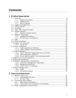
of the hardware used on the Intel Desktop Board DQ67SW A map of the resources of the Intel Desktop Board The features supported by the BIOS Setup program A description of the BIOS error messages, beep codes, and POST codes Regulatory compliance and battery disposal information Typographical - Intel BLKDQ67SWB3 | Product Specification - Page 4
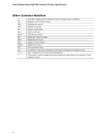
Intel Desktop Board DQ67SW Technical Product Specification Other Common Notation # GB GB/s Gb/s KB Kbit 048,576 bytes) Megabytes per second Megabit (1,048,576 bits) Megabits per second Thermal Design Power An address or data value ending with a lowercase h indicates a hexadecimal value. Volts. - Intel BLKDQ67SWB3 | Product Specification - Page 5
Support 14 1.4 Processor 14 1.5 Intel® Q67 Express Chipset 15 1.6 System Memory 15 1.6.1 Memory Configurations 16 1.7 Graphics Subsystem 18 1.7.1 Integrated Graphics 18 1.7.2 PCI Express x16 Graphics 19 1.8 USB 19 1.9 SATA Interfaces 20 1.10 Legacy I/O Controller 21 1.10.1 Serial Port - Intel BLKDQ67SWB3 | Product Specification - Page 6
Disk Drive Password Security Feature 69 3.8 BIOS Security Features 70 4 Error Messages and Beep Codes 4.1 Speaker 73 4.2 BIOS Beep Codes 73 4.3 Front-panel Power LED Blink Codes 74 4.4 BIOS Error Messages 74 4.5 Port 80h POST Codes 75 5 Regulatory Compliance and Battery Disposal Information - Intel BLKDQ67SWB3 | Product Specification - Page 7
49 20. Front Panel IEEE 1394a Header 49 21. Processor Core Power Connector 50 22. Main Power Connector 50 23. Front Panel Header 51 24. States for a One-Color Power LED 52 25. Alternate Front Panel Power LED Header 52 26. BIOS Setup Configuration Jumper Settings 55 27. Intel MEBX Reset Header - Intel BLKDQ67SWB3 | Product Specification - Page 8
33. BIOS Setup Program Function Keys 64 34. AcceptableDrives/Media Types for BIOS Recovery 67 35. Boot Device Menu Options 68 36. Master Key and User Hard Drive Password Functions 69 37. Supervisor and User Password Functions 71 38. BIOS Beep Codes 73 39. Front-panel Power LED Blink Codes 74 - Intel BLKDQ67SWB3 | Product Specification - Page 9
graphics support for processors with Intel® Graphics Technology: ― DVI-I ― DVI-D ― DisplayPort* • Discrete graphics support for PCI Express 2.0 x16 add-in graphics card • Intel® High Definition Audio: ― Realtek* ALC888S audio codec ― S/PDIF audio header ― DisplayPort Digital Audio ― Front panel - Intel BLKDQ67SWB3 | Product Specification - Page 10
• Support for Advanced Configuration and Power Interface (ACPI), Plug and Play, and SMBIOS • Support for PCI* Local Bus Specification Revision 2.2 • Support for PCI Express* • Suspend to RAM support • Wake on PCI, PCI Express, LAN, front panel, serial, and USB ports LAN Support Gigabit (10/100 - Intel BLKDQ67SWB3 | Product Specification - Page 11
Product Description 1.1.2 Board Layout Figure 1 shows the location of the major components on Intel Desktop Board DQ67SW. Figure 1. Major Board Components Table 2 lists the components identified in Figure 1. 11 - Intel BLKDQ67SWB3 | Product Specification - Page 12
front panel power LED header X Front panel header Y BIOS setup configuration jumper block Z Intel® Management Engine BIOS Extension (Intel® MEBX) Reset header AA SATA connectors BB Intel Fast Call for Help (Intel FCFH) header CC Front panel USB headers (4) DD IEEE 1394a front panel - Intel BLKDQ67SWB3 | Product Specification - Page 13
Product Description 1.1.3 Block Diagram Figure 2 is a block diagram of the major functional areas of the board. Figure 2. Block Diagram 13 - Intel BLKDQ67SWB3 | Product Specification - Page 14
Available configurations for the Intel Desktop Board DQ67SW Visit this World Wide Web site: http://www.intel.com/products/motherboard/index.htm http://www.intel.com/p/en_US/support?iid=hdr+support http://ark.intel.com Supported processors Chipset information BIOS and driver updates Tested memory - Intel BLKDQ67SWB3 | Product Specification - Page 15
the processor and the USB, SATA, LPC, audio, network, display, Conventional PCI, and PCI Express. The PCH is a centralized controller for the board's I/O paths. For information about The Intel Q67 Express chipset Resources used by the chipset Refer to http://www.intel.com/products/desktop/chipsets - Intel BLKDQ67SWB3 | Product Specification - Page 16
Intel Desktop Board DQ67SW Technical Product Specification Table 3 lists the supported DIMM configurations. Table 3. Supported Memory Configurations DIMM Capacity Configuration (Note) SDRAM Density SDRAM Organization Front-side/Back-side Number of SDRAM Devices 512 MB SS 1 Gbit 64 M x16/ - Intel BLKDQ67SWB3 | Product Specification - Page 17
Product Description Figure 3 illustrates the memory channel and DIMM configuration. Figure 3. Memory Channel and DIMM Configuration 17 - Intel BLKDQ67SWB3 | Product Specification - Page 18
or a PCI Express 2.0 x16 add-in graphics card. 1.7.1 Integrated Graphics The board supports integrated graphics through the Intel® Flexible Display Interface (Intel® FDI) for processors with Intel Graphics Technology. NOTE If using a processor with integrated graphics, the board will support only - Intel BLKDQ67SWB3 | Product Specification - Page 19
to the lack of native USB 3.0 driver support from the operating system. For information about The location of the USB connectors on the back panel The location of the front panel USB headers Obtaining USB 3.0 software and drivers Refer to Figure 9, page 44 Figure 10, page 45 Section 1.3, page 14 - Intel BLKDQ67SWB3 | Product Specification - Page 20
mode for configurations using the Windows* XP, Windows Vista*, and Windows 7* operating systems. For more information, see: http://www.serialata.org/. For information about The location of the SATA connectors Refer to Figure 10, page 45 1.9.1.1 Serial ATA RAID The board supports the Intel - Intel BLKDQ67SWB3 | Product Specification - Page 21
wake-up event interface • PCI Conventional bus power management support The BIOS Setup program provides configuration options for the Legacy I/O controller. 1.10.1 Serial Port The serial port is implemented as a 10-pin header on the board. The serial port supports data transfers at speeds up - Intel BLKDQ67SWB3 | Product Specification - Page 22
Intel Desktop Board DQ67SW Technical Product Specification 1.11 Audio Subsystem The board supports Intel High Definition Audio through the Realtek ALC888S audio codec as well as the DisplayPort interface. The Realtek ALC888S-based audio subsystem supports the following features: • 8-channel audio - Intel BLKDQ67SWB3 | Product Specification - Page 23
in Figure 4. Back Panel Audio Connector Options The back panel audio connectors are configurable through the audio device drivers. For information about The back panel audio connectors Refer to Section 2.2.1, page 44 The front panel headphone output is supported using a separate audio channel - Intel BLKDQ67SWB3 | Product Specification - Page 24
: • 10/100/1000 BASE-T IEEE 802.3 compliant • PCI Express link • Compliant to IEEE 802.3x flow control support • 802.1p and 802.1q • TCP, IP, and UDP checksum offload (for IPv4 and IPv6) • Transmit TCP segmentation • Full device driver compatibility • PCI Express power management support • Intel AMT - Intel BLKDQ67SWB3 | Product Specification - Page 25
board is powered up and the LAN subsystem is operating. Table 4. LAN Connector LED States LED LED Color LED State Link/Activity Link Speed Green Green/Yellow Off On Blinking Off Green Yellow Condition LAN link is not established. LAN link is established. LAN activity is occurring. 10 - Intel BLKDQ67SWB3 | Product Specification - Page 26
supply 5V STBY rail. NOTE If the battery and AC power fail date and time values will be reset and the user will be notified during POST. When the voltage drops below a certain level, the BIOS Setup program settings stored in CMOS RAM (for example, the date and time) might not be accurate. Replace - Intel BLKDQ67SWB3 | Product Specification - Page 27
Product Description 1.14 Thermal Monitoring Figure 6 shows the locations of the thermal sensors and fan headers. Item A B C D E Description Thermal diode, located on processor die Processor fan header Front chassis fan header Thermal diode, located on the Intel Q67 PCH Rear chassis fan header - Intel BLKDQ67SWB3 | Product Specification - Page 28
which supports the following: • Processor and system ambient temperature monitoring • Chassis fan speed monitoring • Power monitoring of +12 V, +5 V, +3.3 V, V_SM, and +VCCP • SMBus interface 1.15.2.1 Fan Monitoring Fan monitoring can be observed through the BIOS setup user interface, Intel® Desktop - Intel BLKDQ67SWB3 | Product Specification - Page 29
the operating system or the power state of the system. The Intel Active Management Technology subsystem consists of: • Intel® Management Engine (Intel® ME) microcontroller embedded in the Intel Q67 PCH • Intel 82579LM Gigabit (10/100/1000 Mbits/s) Ethernet LAN controller • BIOS/SPI Flash (64 Mbits - Intel BLKDQ67SWB3 | Product Specification - Page 30
Desktop Board DQ67SW Technical Product Specification • Remote troubleshooting and recovery that can significantly reduce desk-side visits and potentially increasing efficiency of IT technical staff. ⎯ System event log ⎯ IDE Redirection (IDE-R) or PXE boot: remote CD or network drive boot ⎯ Serial - Intel BLKDQ67SWB3 | Product Specification - Page 31
by KVM Remote Control is 1920 x 1200. NOTE KVM Remote Control requires the use of an Intel® processor with integrated graphics. If using simultaneous integrated graphics and add-in PCI Express Graphics, Integrated Graphics Device (IGD) must be set as the Primary Video Device in the BIOS Setup in - Intel BLKDQ67SWB3 | Product Specification - Page 32
required by some operating systems for backward compatibility, such as Windows XP Mode for Windows 7. NOTE Requires an Intel processor that supports Intel VT. 1.15.3.3 Intel® Trusted Execution Technology (Intel® TXT) Intel Trusted Execution Technology (Intel TXT) helps protect the platform against - Intel BLKDQ67SWB3 | Product Specification - Page 33
Advanced Configuration and Power Interface (ACPI) • Hardware support: ⎯ Power connector ⎯ Fan headers ⎯ LAN wake capabilities ⎯ Instantly Available PC technology ⎯ Wake from USB ⎯ Power Management Event signal (PME#) wake-up support ⎯ PCI Express WAKE# signal support ⎯ Wake from serial port 33 - Intel BLKDQ67SWB3 | Product Specification - Page 34
an operating system that provides full ACPI support. ACPI features include: • Plug and Play (including bus and device enumeration) • Power management control of individual devices, add-in boards (some add-in boards may require an ACPI-aware driver), video displays, and hard disk drives • Methods for - Intel BLKDQ67SWB3 | Product Specification - Page 35
the standby power consumption of wake-up devices used in the system. 3. S1 is not supported by the BIOS, it is included for reference only. NOTE In order to support processor Deep Sx states, ME Power Package 1 (ME On in S0) must be selected in the BIOS setup. However, this will disable Intel AMT - Intel BLKDQ67SWB3 | Product Specification - Page 36
. Table 7. Wake-up Devices and Events These devices/events can wake up the computer... Power switch RTC alarm LAN USB PME# signal WAKE# signal Serial port Notes: • S4 implies operating system support only. • USB ports are turned off during S4/S5 states. ...from this state S3, S4, S5 S3, S4, S5 - Intel BLKDQ67SWB3 | Product Specification - Page 37
. The board provides several power management hardware features, including: • Power connector • Fan headers • LAN wake capabilities • Instantly Available PC technology • Wake from USB • PME# signal wake-up support • WAKE# signal wake-up support • Wake from serial port • +5 V Standby Power Indicator - Intel BLKDQ67SWB3 | Product Specification - Page 38
fan control on 3-wire fans For information about The location of the fan headers The location of the fan headers and sensors for thermal monitoring Refer to Figure 10, page 45 Figure 6, page 27 1.16.2.3 LAN Wake Capabilities CAUTION For LAN wake capabilities, the +5 V standby line for the power - Intel BLKDQ67SWB3 | Product Specification - Page 39
will behave as configured by the BIOS "S3 State Indicator" option). When signaled by a wake-up device or event, the system quickly returns to its last known wake state. Table 7 on page 36 lists the devices and events that can wake the computer from the S3 state. The board supports the PCI Bus Power - Intel BLKDQ67SWB3 | Product Specification - Page 40
Intel Desktop Board DQ67SW Technical Product Specification 1.16.2.9 +5 V Standby Power LED The green +5 V standby power indicator LED shows that power is still present even when the computer appears to be off. Figure 7 shows the location of the Standby Power indicator LED on the board. CAUTION If AC - Intel BLKDQ67SWB3 | Product Specification - Page 41
(40 MB) • Front side bus interrupts (17 MB) • PCI Express configuration space (256 MB) • PCH base address registers PCI Express ports (up to 256 MB) • Memory-mapped I/O that is dynamically allocated for PCI Conventional and PCI Express add-in cards (256 MB) The board provides the capability to - Intel BLKDQ67SWB3 | Product Specification - Page 42
Intel Desktop Board DQ67SW Technical Product Specification Figure 8. Detailed System Memory Address Map 42 - Intel BLKDQ67SWB3 | Product Specification - Page 43
Reserved Potential available high DOS Video me(mory andhBIOS Extended BIOS data (movable by Extended conventionfal mem) ory Conventional memory 2.2 Connectors and Headers CAUTION Only the following connectors and headers have overcurrent protection: back panel and front panel USB, as well as IEEE - Intel BLKDQ67SWB3 | Product Specification - Page 44
Intel Desktop Board DQ67SW Technical Product Specification 2.2.1 Back Panel Connectors Figure 9 shows the location of the back panel connectors for the board. Item A B C D E F G H I J K L Description LAN USB 3.0 ports DVI-I connector DVI-D connector DisplayPort connector USB ports eSATA ports IEEE - Intel BLKDQ67SWB3 | Product Specification - Page 45
Technical Reference 2.2.2 Component-side Connectors and Headers Figure 10 shows the locations of the component-side connectors and headers. Figure 10. Component-side Connectors and Headers Table 9 lists the component-side connectors and headers identified in Figure 10. 45 - Intel BLKDQ67SWB3 | Product Specification - Page 46
PCI Express x16 bus add-in card connector 12 V internal power connector (ATX12V) Processor fan header Serial port header Chassis intrusion header Front chassis fan header Main power connector (2 x 12) Alternate front panel power LED header Front panel header Intel MEBX Reset header P SATA - Intel BLKDQ67SWB3 | Product Specification - Page 47
Pin Signal Name 1 − 2 + Table 13. Front Panel Audio Header for Intel HD Audio Pin Signal Name Pin Signal Name 1 [Port 1] Left channel 3 [Port 1] Right channel 5 [Port 2] Right channel 7 SENSE_SEND (Jack detection) 9 [Port 2] Left channel 2 Ground 4 PRESENCE# (Dongle present - Intel BLKDQ67SWB3 | Product Specification - Page 48
all AC '97 signals are supported; specifically, pins 4, 6, 7, and 10 are not supported. Table 15. Front Panel USB Header Pin Signal Name Pin 1 +5 VDC 2 3 D- 4 5 D+ 6 7 Ground 8 9 KEY (no pin) 10 Signal Name +5 VDC DD+ Ground No Connect Table 16. SATA Connectors Pin Signal Name - Intel BLKDQ67SWB3 | Product Specification - Page 49
4 FAN_CONTROL Pin 3-Wire Support 3 Ground 2 FAN_POWER 1 FAN_TACH N/A N/A Table 20. Front Panel IEEE 1394a Header Pin Signal Name Pin 1 Data A (positive) 2 3 Ground 4 5 Data B (positive) 6 7 +12V_DC 8 9 Key (no pin) 10 Note: The +12 V DC power on the IEEE 1394a header - Intel BLKDQ67SWB3 | Product Specification - Page 50
is compatible with 2 x 10 connectors previously used on Intel Desktop boards. The board supports the use of ATX12V power supplies with either 2 x 10 or 2 x 12 main power cables. When using a power supply with a 2 x 10 main power cable, pins 11, 12, 23, and 24 must remain unconnected. • Processor - Intel BLKDQ67SWB3 | Product Specification - Page 51
5 Ground Ground 7 FP_RESET# In Reset switch Power 9 +5 V Power Pin Signal Power LED 2 FP_LED+ 4 FP_LED− On/Off Switch 6 PWR# 8 Ground Not Connected 10 N/C In/ Out Description Out Front panel green LED Out Front panel yellow LED In Power switch Ground Not connected - Intel BLKDQ67SWB3 | Product Specification - Page 52
options are available through BIOS setup. Table 24. States for a One-Color Power LED LED State Description Off Power off/sleeping Steady Lit Running Blink Standby 2.2.2.4.4 Power Switch Header Pins 6 and 8 can be connected to a front panel momentary-contact power switch. The switch must - Intel BLKDQ67SWB3 | Product Specification - Page 53
Front Panel USB Headers Figure 12 is a connection diagram for the front panel USB headers. NOTE • The +5 V DC power on the USB headers is fused. • Use only a front panel USB connector that conforms to the USB 2.0 specification for high-speed USB devices. Figure 12. Connection Diagram for Front Panel - Intel BLKDQ67SWB3 | Product Specification - Page 54
Intel Desktop Board DQ67SW Technical Product Specification 2.3 BIOS Configuration Jumper Block CAUTION Do not move the jumper with the power on. Always turn off the power and unplug the power cord from the computer before changing a jumper setting. Otherwise, the board could be damaged. Figure 13 - Intel BLKDQ67SWB3 | Product Specification - Page 55
/PPS and user entered Hash Certificates. USB key and remote configuration data will be removed if the parameters are not default parameters. • Reset the Intel MEBX password to the default value (admin). CAUTION Always turn off the power and unplug the power cord from the computer before installing - Intel BLKDQ67SWB3 | Product Specification - Page 56
Intel Desktop Board DQ67SW Technical Product Specification Figure 14. Intel MEBX Reset Header Table 27. Intel MEBX Reset Header Signals Pin Function 1 PCH.AK24 (PCH_RTCRST_PULLUP) 2 Ground 3 No connection 56 - Intel BLKDQ67SWB3 | Product Specification - Page 57
is designed to fit into a microATX form-factor chassis. Figure 15 illustrates the mechanical form factor for the board. Dimensions are given in inches [millimeters]. The outer dimensions are 9.60 inches by 9.60 inches [243.84 millimeters by 243.84 millimeters]. Location of the I/O - Intel BLKDQ67SWB3 | Product Specification - Page 58
on page 14 for information on supported processors), 2 GB DDR3 RAM, one high end video card, one hard disk drive, one optical drive, and all board peripherals enabled, the minimum recommended power supply is 460 W. Table 28 lists the recommended power supply current values. Table 28. Recommended - Intel BLKDQ67SWB3 | Product Specification - Page 59
damage that will halt fan operation. Table 29 lists the current capability of the fan headers. Table 29. Fan Header Current Capability Fan Header Maximum Available Current Processor fan Front chassis fan Rear chassis fan 2.0 A 1.5 A 1.5 A 2.6.3 Add-in Board Considerations The board is designed - Intel BLKDQ67SWB3 | Product Specification - Page 60
processor voltage regulator area is highly recommended. For a list of chassis that have been tested with Intel desktop boards please refer to the following website: http://www3.intel Intel makes no warranties or representations that merely following the instructions presented in this document will - Intel BLKDQ67SWB3 | Product Specification - Page 61
important when considering proper airflow to cool the board. Table 30. Thermal Considerations for Components Component Maximum Case Temperature Processor For processor case temperature, see processor datasheets and processor specification updates Intel Q67 Express Chipset 111 oC (under bias - Intel BLKDQ67SWB3 | Product Specification - Page 62
Intel Desktop Board DQ67SW Technical Product Procedure for Electronic Equipment" (Reference Model Telcordia SR-332 Issue 2, Reference Method Telcordia (Bellcore) Method I, Case 3). the board is 220,573 hours. 2.9 Environmental Table 31 lists the environmental specifications for the board. Table - Intel BLKDQ67SWB3 | Product Specification - Page 63
Security Power Boot Intel ME Exit NOTE The maintenance menu is displayed only when the board is in configure mode. Section 2.3 on page 54 shows how to put the board in configure mode. CAUTION Resetting the BIOS to defaults may result in the system becoming unbootable or corrupting the HDD if RAID is - Intel BLKDQ67SWB3 | Product Specification - Page 64
Intel Desktop Board DQ67SW Technical Product Specification Table 32 lists the BIOS Setup program menu features. Table 32. BIOS Setup Program Menu Bar Maintenance Main Configura- tion Performance Security Clears passwords and displays processor information Displays processor and memory - Intel BLKDQ67SWB3 | Product Specification - Page 65
operating system's USB drivers are not yet available. Legacy USB support is used to access the BIOS Setup program, and to install an operating system that supports USB. By default, Legacy USB support is set to Enabled. Legacy USB support operates as follows: 1. When you apply power to the computer - Intel BLKDQ67SWB3 | Product Specification - Page 66
an incompatible BIOS. NOTE Review the instructions distributed with the upgrade utility before attempting a BIOS update. For information about BIOS update utilities Refer to http://www.intel.com/support/motherboards/desktop/sb/CS022312.htm. 3.4.1 Language Support The BIOS Setup program and - Intel BLKDQ67SWB3 | Product Specification - Page 67
/ http://developer.intel.com/products/motherboard/DQ67SW /tools.htm and http://developer.intel.com/design/motherbd/software.htm 3.5 BIOS Recovery It is unlikely that anything will interrupt a BIOS update; however, if an interruption occurs, the BIOS could be damaged. Table 34 lists the drives and - Intel BLKDQ67SWB3 | Product Specification - Page 68
Intel Desktop Board DQ67SW Technical Product Specification 3.6 Boot Options In the BIOS Setup program, the user can choose to boot from a hard drive, optical drive, removable drive, or the network. The default setting is for the optical drive - Intel BLKDQ67SWB3 | Product Specification - Page 69
with the message: Hard Disk Drive Password Entry Error A manual power cycle will be required to resume system operation. NOTE As implemented on DQ67SW, Hard Disk Drive Password Security is only supported on SATA port 0. The passwords are stored on the hard disk drive so if the drive is relocated - Intel BLKDQ67SWB3 | Product Specification - Page 70
Intel Desktop Board DQ67SW Technical Product Specification NOTE Hard Disk Drive Password Security is not supported in PCH RAID mode. Secured hard disk drives attached to the system when the system is in PCH RAID mode will not be accessible due to the disabling of BIOS Hard Disk Drive Password - Intel BLKDQ67SWB3 | Product Specification - Page 71
Overview of BIOS Features Table 37 shows the effects of setting the supervisor password and user password. This table is for reference only and is not displayed on the screen. Table 37. Supervisor and User Password Functions Password Set Supervisor Mode User Mode Setup Options Neither Can - Intel BLKDQ67SWB3 | Product Specification - Page 72
Intel Desktop Board DQ67SW Technical Product Specification 72 - Intel BLKDQ67SWB3 | Product Specification - Page 73
during POST, the BIOS causes the board's piezoelectric speaker to beep an error message describing the problem (see Table 38). Table 38. BIOS Beep Codes Type Pattern F2 Setup/F10 Boot Menu One 0.5 second beep when BIOS is ready to Prompt accept keyboard input BIOS update in progress None - Intel BLKDQ67SWB3 | Product Specification - Page 74
Intel Desktop Board DQ67SW Technical Product Specification 4.3 Front-panel Power LED Blink Codes Whenever a recoverable error occurs during POST, the BIOS causes the board's front panel power LED to blink an error message describing the problem (see Table 39). Table 39. Front-panel Power LED - Intel BLKDQ67SWB3 | Product Specification - Page 75
seven-segment display. NOTE The POST card must be installed in the PCI bus connector. The following tables provide information about the POST codes generated by the BIOS: • Table 41 lists the Port 80h POST code ranges • Table 42 lists the Port 80h POST codes themselves • Table 43 lists the Port 80h - Intel BLKDQ67SWB3 | Product Specification - Page 76
Intel Desktop Board DQ67SW Technical Product Specification Table 42. Port 80h POST Codes Port 80 Code Progress Code Enumeration ACPI S States 0x00,0x01,0x02,0x03,0x04,0x05 Entering S0, S2, S3, S4, or S5 state 0x10,0x20,0x30,0x40,0x50 Resuming from S2, S3, S4, S5 Security Phase (SEC) 0x08 - Intel BLKDQ67SWB3 | Product Specification - Page 77
0x4E Relocate SM bases for all APs 0x4F CPU DXE SMM Phase end I/O BUSES 0x50 Enumerating PCI busses 0x51 Allocating resources to PCI bus 0x52 Hot Plug PCI controller initialization USB 0x58 Resetting USB bus 0x59 Reserved for USB ATA/ATAPI/SATA 0x5A Resetting PATA/SATA bus and all - Intel BLKDQ67SWB3 | Product Specification - Page 78
Intel Desktop Board DQ67SW Technical Product Specification Table 42. Port 80h POST Codes (continued) Port 80 Code Progress Code Enumeration 0x60 0x61 0x62 0x63 0x64 0x65 0x66 0x67 0x68 0x69 0x6A 0x6B 0x6C 0x6D 0x6E 0x6F 0x90 0x91 0x92 0x93 0x94 0x95 0x98 0x99 0x9A 0x9B 0xB0 0xB1 BDS BDS driver - Intel BLKDQ67SWB3 | Product Specification - Page 79
and Beep Codes Table 42. Port 80h POST Codes (continued) Port 80 Code Progress Code Enumeration Removable Media 0xB8 Resetting removable media 0xB9 Disabling removable media 0xBA Detecting presence of a removable media (IDE, CDROM detection etc.) 0xBB Enabling/configuring a removable - Intel BLKDQ67SWB3 | Product Specification - Page 80
Intel Desktop Board DQ67SW Technical Product Specification Table 43. Typical Port 80h POST Sequence POST Code Description 21 Initializing a chipset component 22 Reading SPD from memory DIMMs 23 Detecting presence of memory DIMMs 25 Configuring memory 28 Testing memory 34 Loading - Intel BLKDQ67SWB3 | Product Specification - Page 81
standards • European Union Declaration of Conformity statement • Product Ecology statements • Electromagnetic Compatibility (EMC) standards • Product certification markings 5.1.1 Safety Standards The Intel Desktop Board DQ67SW complies with the safety standards stated in Table 44 when correctly - Intel BLKDQ67SWB3 | Product Specification - Page 82
Statement We, Intel Corporation, declare under our sole responsibility that the product Intel® Desktop Board DQ67SW is in 2006/95/EC, and 2002/95/EC. Čeština Tento výrobek odpovídá požadavkům evropských směrnic 2004/108/EC, 2006/95/EC a 2002/95/EC. Dansk Dette produkt er i overensstemmelse - Intel BLKDQ67SWB3 | Product Specification - Page 83
of this program, including the scope of covered products, available locations, shipping instructions, terms and conditions, etc Intel Product Recycling Program http://www.intel.com/intel/other/ehs/product_ecology Deutsch Als Teil von Intels Engagement für den Umweltschutz hat das Unternehmen das - Intel BLKDQ67SWB3 | Product Specification - Page 84
Intel Desktop Board DQ67SW Technical Product Specification Español Como parte de su compromiso de responsabilidad medioambiental, Intel ha implantado el programa de reciclaje de productos Intel, que permite que los consumidores al detalle de los productos Intel devuelvan los productos usados en los - Intel BLKDQ67SWB3 | Product Specification - Page 85
Intel Desktop Board DQ67SW complies with the EMC regulations stated in Table 45 when correctly installed in a compatible host system. Table 45. EMC Regulations Regulation Title FCC 47 CFR Part 15, Subpart B ICES-003 Title 47 of the Code , KN-24 Voluntary Control for Interference by Information - Intel BLKDQ67SWB3 | Product Specification - Page 86
Intel Desktop Board DQ67SW Technical Product Specification FCC Declaration of Conformity This device complies with and used in accordance with the instructions, may cause harmful interference to radio communications. However, there is no guarantee that interference will not occur in a particular - Intel BLKDQ67SWB3 | Product Specification - Page 87
or television receiver in a domestic environment, it may cause radio interference. Install and use the equipment according to the instruction manual. Korea Class B Statement Korea Class B Statement translation: This equipment is for home use, and has acquired electromagnetic conformity registration - Intel BLKDQ67SWB3 | Product Specification - Page 88
in the definition of new requirements. Intel Desktop Board DQ67SW meets the following program requirements in an adequate system configuration, including appropriate selection of an efficient power supply: • Energy Star v5.0, category A • EPEAT* • Korea e-Standby • European Union Energy-related - Intel BLKDQ67SWB3 | Product Specification - Page 89
Intel supplier code number, N-232. Japan VCCI (Voluntary Control Council for Interference) mark. KCC (Korean Communications Commission) EMC certification mark. Includes adjacent KCC certification number: CPU-DQ67SW of the symbol used on Intel Desktop Boards and associated collateral. The color - Intel BLKDQ67SWB3 | Product Specification - Page 90
Intel Desktop Board DQ67SW Technical Product Specification 5.2 Battery Disposal Information CAUTION Risk of explosion if the battery is replaced with an incorrect type. Batteries should be recycled where possible. - Intel BLKDQ67SWB3 | Product Specification - Page 91
Regulatory Compliance and Battery Disposal Information PRECAUCIÓN Existe peligro de explosión si la pila no se cambia de forma adecuada. Utilice solamente pilas iguales o del mismo tipo que las recomendadas por el fabricante del equipo. Para deshacerse de las pilas usadas, siga igualmente las - Intel BLKDQ67SWB3 | Product Specification - Page 92
Intel Desktop Board DQ67SW Technical Product Specification AWAS Risiko letupan wujud jika bateri digantikan dengan jenis yang tidak betul. Bateri sepatutnya dikitar semula jika boleh. Pelupusan bateri terpakai mestilah - Intel BLKDQ67SWB3 | Product Specification - Page 93
Regulatory Compliance and Battery Disposal Information 93 - Intel BLKDQ67SWB3 | Product Specification - Page 94
Intel Desktop Board DQ67SW Technical Product Specification 94
-
 1
1 -
 2
2 -
 3
3 -
 4
4 -
 5
5 -
 6
6 -
 7
7 -
8
-
9
-
10
-
11
-
12
-
13
-
14
-
15
-
16
-
17
-
18
-
19
-
20
-
21
-
22
-
23
-
24
-
25
-
26
-
27
-
28
-
29
-
30
-
31
-
32
-
33
-
34
-
35
-
36
-
37
-
38
-
39
-
40
-
41
-
42
-
43
-
44
-
45
-
46
-
47
-
48
-
49
-
50
-
51
-
52
-
53
-
54
-
55
-
56
-
57
-
58
-
59
-
60
-
61
-
62
-
63
-
64
-
65
-
66
-
67
-
68
-
69
-
70
-
71
-
72
-
73
-
74
-
75
-
76
-
77
-
78
-
79
-
80
-
81
-
82
-
83
-
84
-
85
-
86
-
87
-
88
-
89
-
90
-
91
-
92
-
93
-
94
 |
 |

Intel® Desktop Board
DQ67SW
Technical Product Specification
January 2011
Order Number:
G14714-001US
The Intel
®
Desktop Board DQ67SW may contain design defects or errors known as errata that may cause the product to deviate from published
specifications.
Current characterized errata are documented in the Intel Desktop Board DQ67SW Specification Update.