Intel BOXD845GVSR Product Specification
Intel BOXD845GVSR Manual
 |
View all Intel BOXD845GVSR manuals
Add to My Manuals
Save this manual to your list of manuals |
Intel BOXD845GVSR manual content summary:
- Intel BOXD845GVSR | Product Specification - Page 1
July 2003 Order Number: C46811-001 The Intel® Desktop Board D845GVSR may contain design defects or errors known as errata that may cause the product to deviate from published specifications. Current characterized errata are documented in the Intel Desktop Board D845GVSR Specification Update. - Intel BOXD845GVSR | Product Specification - Page 2
and plans at any time, without notice. The Intel® Desktop Board D845GVSR may contain design defects or errors known as errata ordering number and are referenced in this document, or other Intel literature, may be obtained from: Intel Corporation P.O. Box 5937 Denver, CO 80217-9808 or call in North - Intel BOXD845GVSR | Product Specification - Page 3
and environmental requirements, and the BIOS for the Intel® Desktop Board D845GVSR. It describes the standard product and available of the hardware used on the Desktop Board D845GVSR A map of the resources of the Desktop Board The features supported by the BIOS Setup program The contents of - Intel BOXD845GVSR | Product Specification - Page 4
Intel Desktop Board D845GVSR Technical Product Specification WARNING Warnings indicate conditions, , N indicates component type, xn are the relative coordinates of its location on the Desktop Board D845GVSR, and X is the instance of the particular part at that general location. For example, J5J1 - Intel BOXD845GVSR | Product Specification - Page 5
13 1.1.3 Board Layout 14 1.2 Block Diagram ...15 1.3 Online Support ...16 1.4 Operating System Support 16 1.5 Design Specifications 17 1.6 Processor ...20 1.7 System Memory ...21 1.8 Intel® 845GV Chipset 23 1.8.1 Intel® Extreme Graphics Controller 23 1.8.2 USB...28 1.8.3 IDE Interfaces 28 - Intel BOXD845GVSR | Product Specification - Page 6
Intel Desktop Board D845GVSR Support 72 3.6.2 Custom Splash Screen 73 3.7 Recovering BIOS Data 73 3.8 Boot Options...74 3.8.1 CD-ROM Boot 74 3.8.2 Network Boot 74 3.8.3 Booting Without Attached Devices 74 3.8.4 Changing the Default Boot Device During POST 74 3.9 Fast Booting Systems with Intel - Intel BOXD845GVSR | Product Specification - Page 7
Initialization Checkpoints 107 5.4 Speaker ...108 5.5 BIOS Beep Codes ...108 Figures 1. Desktop Board D845GVSR Components 14 2. Block Diagram ...15 3. Location of the Standby Power Indicator LED on the D845GVSR Board 40 4. Back Panel Connectors 48 5. Audio, Power, and Hardware Control Connectors - Intel BOXD845GVSR | Product Specification - Page 8
Intel Desktop Board D845GVSR Technical Product Specification Tables 1. Feature Summary...12 2. Manufacturing Options 13 3. Specifications ...17 4. Supported System Bus Frequency and Memory Speed Combinations 21 5. Supported DDR DIMM Configurations 22 6. Direct Draw Supported Modes 24 7. Video - Intel BOXD845GVSR | Product Specification - Page 9
Contents 47. BIOS Setup Program Function Keys 78 48. Maintenance Menu ...78 49. Main Menu...79 50. Advanced Menu...80 51. PCI Configuration Submenu 81 52. Boot Configuration Submenu 82 53. Peripheral Configuration Submenu 83 54. IDE Configuration Submenu 85 55. Primary/Secondary IDE Master/ - Intel BOXD845GVSR | Product Specification - Page 10
Intel Desktop Board D845GVSR Technical Product Specification x - Intel BOXD845GVSR | Product Specification - Page 11
Description What This Chapter Contains 1.1 Overview ...12 1.2 Block Diagram ...15 1.3 Online Support ...16 1.4 Operating System Support 16 1.5 Design Specifications 17 1.6 Processor ...20 1.7 System Memory ...21 1.8 Intel® 845GV Chipset 23 1.9 I/O Controller ...30 1.10 Audio Subsystem...31 1.11 - Intel BOXD845GVSR | Product Specification - Page 12
Feature Summary Table 1 summarizes the major features of the Intel® Desktop Board D845GVSR. Table 1. Feature Summary Form Factor Processor microATX (9.20 inches by 8.20 inches [233.68 millimeters by 208.28 millimeters]) • Support for an Intel® Pentium® 4 processor in an mPGA478 socket with a 400 - Intel BOXD845GVSR | Product Specification - Page 13
Manufacturing Options Table 2 describes the manufacturing options on the Desktop Board D845GVSR. Not every manufacturing option is available in all marketing channels. Please contact your Intel representative to determine which manufacturing options are available to you. Table 2. Manufacturing - Intel BOXD845GVSR | Product Specification - Page 14
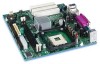
on the Desktop Board D845GVSR. A B CD E BB F G H AA I Z J Y K X L W VU T S R Q P O NM OM16233 A Audio codec B Intel 82562ET 10/100 Mbit/ Hub (FWH) X Front panel connector Y Front panel USB connector Z Intel 82801DB I/O Controller Hub (ICH4) AA PCI bus add-in card connectors - Intel BOXD845GVSR | Product Specification - Page 15
MHz) USB LPC Bus I/O Controller SMBus LPC Bus Back Panel / Front Panel USB Ports Serial Ports Parallel Port PS/2 Mouse PS/2 Keyboard Diskette Drive Connector Intel 82845GV Graphics and Memory Controller Hub (GMCH) AHA Bus VGA Port DIMM Banks (2) Display Interface Memory Bus SMBus PCI Bus - Intel BOXD845GVSR | Product Specification - Page 16
.htm http://www.intel.com/design/litcentr http://developer.intel.com/design/chipsets/datashts http://intel.com/design/motherbd/gen_indx.htm http://www.intel.com/design/motherbd http://www.intel.com/design/motherbd 1.4 Operating System Support The Desktop Board D845GVSR supports drivers for all - Intel BOXD845GVSR | Product Specification - Page 17
3 lists the specifications applicable to the Desktop Board D845GVSR. Table 3. Specifications Reference Name AC '97 ACPI ASF December 1998, Intel Corporation. ATX12V ATX/ATX12V Power Supply Design Guide Version 1.2, August 2000, Intel Corporation. BIS DDR SDRAM Boot Integrity Services (BIS) - Intel BOXD845GVSR | Product Specification - Page 18
Intel Desktop Board D845GVSR Technical Product Specification Table 3. Specifications (continued) Reference Name EHCI Execution Environment SFX/SFX12V Power Supply Design Guide Version, Revision Date and Ownership Revision 1.0, March 12, 2002, Intel Corporation. Version 1.7, 1997, Institute of - Intel BOXD845GVSR | Product Specification - Page 19
Guide Universal Serial Bus Specification Version, Revision Date and Ownership Version 2.3.1, March 16, 1999, American Megatrends Incorporated, Award Software International Incorporated, Compaq Computer Corporation, Dell Computer Corporation, Hewlett-Packard Company, Intel 1998, Intel Corporation. - Intel BOXD845GVSR | Product Specification - Page 20
an mPGA478 processor socket with a 400 MHz system bus See the Intel web site listed below for the most up-to-date list of supported processors. For information about... Supported processors for the D845GVSR board Refer to: http://www.intel.com/design/motherbd/sr/sr_proc.htm CAUTION Use only the - Intel BOXD845GVSR | Product Specification - Page 21
Product Description 1.7 System Memory The Desktop Board D845GVSR has two DIMM sockets and supports the following memory features: • 2.5 V (only) 184-pin DDR SDRAM DIMMs with gold-plated contacts • Unbuffered single-sided or double-sided DIMMs • Maximum total system memory: 2 - Intel BOXD845GVSR | Product Specification - Page 22
Intel Desktop Board D845GVSR Technical Product Specification Table 5 lists the supported DDR DIMM configurations. Table 5. Supported DDR DIMM Configurations DIMM Capacity Configuration DDR SDRAM (Note) Density DDR SDRAM Organization Number of DDR Front-side/Back-side SDRAM Devices 64 MB - Intel BOXD845GVSR | Product Specification - Page 23
Intel 845GV chipset Resources used by the chipset Refer to http://developer.intel.com/ Chapter 2 1.8.1 Intel® Extreme Graphics Controller The Intel software MPEG2 decode • Dynamic Video Memory Technology (DVMT) support up to 64 MB For information about DVMT Refer to Section 1.8.1.1, page 27 - Intel BOXD845GVSR | Product Specification - Page 24
Intel Desktop Board D845GVSR Technical Product Specification Table 6 lists the Direct Draw supported modes. Table 6. Direct Draw Supported Modes Resolution 320 x 200 Color Palette 256 colors Refresh Frequency (Hz) Notes 70 Y 64 K colors 70 3 16 M colors 70 3 320 x 240 256 colors 70 - Intel BOXD845GVSR | Product Specification - Page 25
Product Description Table 7 lists the video BIOS video modes supported by the graphics subsystem. Table 7. Video BIOS Video Modes Supported for Analog CRTs Resolution 320 x 200 320 x 350 360 x 400 640 x 200 640 x 350 640 x 480 Color Palette 16 colors 256 colors 16 colors 16 - Intel BOXD845GVSR | Product Specification - Page 26
Intel Desktop Board D845GVSR Technical Product Specification Table 8 lists the supported configuration modes of the graphics subsystem. Table 8. Supported Configuration Modes Resolution Available Refresh Frequencies (Hz) Supported bpp Configuration Mode (see Table 9 for more information) 640 x - Intel BOXD845GVSR | Product Specification - Page 27
. For information about Obtaining the DVMT white paper Refer to http://developer.intel.com/design/chipsets/845gv/ 1.8.1.2 Zone Rendering Technology (ZRT) The Intel Extreme Graphics Controller supports Zone Rendering Technology (ZRT). ZRT is a process by which the screen is divided into several - Intel BOXD845GVSR | Product Specification - Page 28
Intel Desktop Board D845GVSR Technical Product Specification • Increased headroom for larger resolution and color Rendering white paper Refer to http://developer.intel.com/design/chipsets/845gv/ 1.8.2 USB The board supports up to six USB 2.0 ports, fully supports UHCI and EHCI, and uses UHCI- - Intel BOXD845GVSR | Product Specification - Page 29
(ECHS) translation modes. The drive reports the transfer rate and translation mode to the BIOS. The Desktop Boards support Laser Servo (LS-120) diskette technology through the IDE interfaces. The BIOS supports booting from an LS-120 drive. ✏ NOTE The BIOS will always recognize an LS-120 drive as an - Intel BOXD845GVSR | Product Specification - Page 30
Intel Desktop Board D845GVSR Technical Product Specification 1.9 I/O Controller The SMSC LPC47M172 or National Semiconductor PC87372 I/O controller provides the following features: • One serial port • One parallel port with Extended Capabilities Port (ECP) and Enhanced Parallel Port (EPP) support - Intel BOXD845GVSR | Product Specification - Page 31
Intel 82801DB I/O Controller Hub (ICH4) • Realtek ALC202A audio codec The audio subsystem includes these features: • Signal-to-noise ratio ≥ 90 dB • Supports the front panel audio connector Obtaining the Front Panel I/O Connectivity Design Guide Refer to Figure 5, page 50 Table 21, page 51 Section - Intel BOXD845GVSR | Product Specification - Page 32
Intel Desktop Board D845GVSR Technical Product Specification 1.10.1.3 ATAPI CD-ROM Audio Connector A 1 x panel RJ-45 connector with integrated LEDs. The Intel 82562ET provides the following functions: • Basic 10/100 Ethernet LAN connectivity • Supports RJ-45 connector with status indicator LEDs on - Intel BOXD845GVSR | Product Specification - Page 33
) The computer is communicating with another computer on the LAN. 1.11.3 LAN Subsystem Software LAN software and drivers are available from Intel's World Wide Web site. For information about Obtaining LAN software and drivers Refer to Section 1.3, page 16 1.12 Hardware Management Subsystem - Intel BOXD845GVSR | Product Specification - Page 34
Fan monitoring can be implemented using Intel® LANDesk Client Manager or third-party software. For information about The functions of the fan connectors Refer to Section 1.13.2.2, page 38 1.12.3 Chassis Intrusion and Detection The board supports a chassis security feature that detects if - Intel BOXD845GVSR | Product Specification - Page 35
applications and user settings to put the system as a whole into a low-power state. Table 12 lists the power states supported by the Desktop Board D845GVSR along with the associated system power targets. See the ACPI specification for a complete description of the various system and power states - Intel BOXD845GVSR | Product Specification - Page 36
Intel Desktop Board D845GVSR Technical Product Specification Table 12. Power States and Targeted System -up logic, except when provided by battery or external source. No power to the system. Service can be performed safely. Notes: 1. Total system power is dependent on the system configuration, - Intel BOXD845GVSR | Product Specification - Page 37
can damage the power supply. The total amount of standby current required depends on the wake devices supported and manufacturing options. The Desktop Board D845GVSR provides several power management hardware features, including: • Power connector • Fan connectors • LAN wake capabilities • Instantly - Intel BOXD845GVSR | Product Specification - Page 38
Intel Desktop Board D845GVSR Technical Product Specification 1.13.2.1 Power Connector ATX12V-, SFX12V-, and TFX12V-compliant power supplies can turn off the system power through system control. When an ACPI- - Intel BOXD845GVSR | Product Specification - Page 39
can participate in power management and can be used to wake the computer. The use of Instantly Available PC technology requires operating system support and PCI 2.2 compliant add-in cards and drivers. 1.13.2.5 +5 V Standby Power Indicator LED The +5 V standby power indicator LED shows that power is - Intel BOXD845GVSR | Product Specification - Page 40
Intel Desktop Board D845GVSR Technical Product Specification CR1F1 OM16234 Figure 3. Location of the Standby Power Indicator LED on the D845GVSR states. ✏ NOTE Wake from USB requires the use of a USB peripheral that supports Wake from USB. 1.13.2.8 Wake from PS/2 Devices PS/2 device activity wakes - Intel BOXD845GVSR | Product Specification - Page 41
2 Technical Reference What This Chapter Contains 2.1 Introduction...41 2.2 Memory Map ...41 2.3 Fixed I/O Map...42 2.4 DMA Channels ...43 2.5 PCI Configuration Space Map 43 2.6 Interrupts ...44 2.7 PCI Interrupt Routing Map 45 2.8 Connectors ...47 2.9 Jumper Blocks...58 2.10 Mechanical - Intel BOXD845GVSR | Product Specification - Page 42
Intel Desktop Board D845GVSR Technical Product Specification 2.3 Fixed I/O Map Table 16. I/O Map Address (hex) 0000 - 00FF Size 256 bytes Description Used by the Desktop Board D845GVSR. Refer to the ICH4 data sheet for dynamic addressing information. 0170 - 0177 01F0 - 01F7 0228 - 022F (Note - Intel BOXD845GVSR | Product Specification - Page 43
00 1D 07 01 08 00 01 00 00 01 01 00 01 02 00 Description Memory controller of Intel 82845GV component Intel Extreme Graphics Controller Hub link to PCI bridge Intel 82801DB ICH4 PCI to LPC bridge IDE controller SMBus controller AC '97 audio controller AC '97 modem controller (optional - Intel BOXD845GVSR | Product Specification - Page 44
Intel Desktop Board D845GVSR Technical Product Specification 2.6 Interrupts The interrupts can be routed through either the Programmable Interrupt Controller (PIC) or the Advanced Programmable Interrupt Controller (APIC) portion of the ICH4 component. The PIC is supported in Windows 98 SE and - Intel BOXD845GVSR | Product Specification - Page 45
or from a PCI add-in card connect to one of these PIRQ signals. Some PCI interrupt sources are electrically tied together on the Desktop Board D845GVSR and therefore share the same interrupt. Table 20 shows an example of how the PIRQ signals are routed. For example, using Table 20 as a reference - Intel BOXD845GVSR | Product Specification - Page 46
Intel Desktop Board D845GVSR Technical Product Specification Table 20. PCI Interrupt Routing Map PCI Interrupt Source PIRQA Intel Extreme Graphics Controller INTA ICH4 USB UHCI controller 1 INTA SMBus controller ICH4 USB UHCI controller 2 AC '97 ICH4 Audio/Modem ICH4 LAN ICH4 USB UHCI - Intel BOXD845GVSR | Product Specification - Page 47
Technical Reference 2.8 Connectors CAUTION Only the back panel USB, front panel USB, VGA, and PS/2 connectors have overcurrent protection. The Desktop Boards' internal connectors are not overcurrent protected and should connect only to devices inside the computer's chassis, such as fans and internal - Intel BOXD845GVSR | Product Specification - Page 48
Intel Desktop Board D845GVSR Technical Product Specification 2.8.1 Back Panel Connectors Figure 4 shows the location of the back panel connectors. The back panel connectors are color-coded in compliance with - Intel BOXD845GVSR | Product Specification - Page 49
Technical Reference # INTEGRATOR'S NOTE The back panel audio line out connector is designed to power headphones or amplified speakers only. Poor audio quality occurs if passive (non-amplified) speakers are connected to this output. 2.8.2 Internal I/O Connectors The internal I/O connectors are - Intel BOXD845GVSR | Product Specification - Page 50
Intel Desktop Board D845GVSR Technical Product Specification 2.8.2.2 Audio, Power, and Hardware Control Connectors Figure 5 shows the location of the audio, power, and hardware control connectors. AB C D 1 4 12 9 10 1 4 12 - Intel BOXD845GVSR | Product Specification - Page 51
Technical Reference Table 21. Front Panel Audio Connector Pin Signal Name Pin 1 MIC_IN 2 3 MIC_BIAS 4 5 RIGHT_OUT 6 7 No connect 8 9 LEFT_OUT 10 Signal Name Ground +5 V RIGHT_IN Key LEFT_IN Table 22. Auxiliary Line In Connector Pin Signal Name 1 Left auxiliary line in 2 - Intel BOXD845GVSR | Product Specification - Page 52
Intel Desktop Board D845GVSR Technical Product Specification Table 25. Rear Chassis Fan Connector Pin Signal Name 1 Ground (default) or FNT_REAR_FAN_CTRL (optional) 2 +12 V 3 No connect (default) or REAR_TACH_OUT (optional) Table - Intel BOXD845GVSR | Product Specification - Page 53
add-in board connector and peripheral connectors for the Desktop Board D845GVSR. Note the following considerations for the PCI bus connectors: routed to PCI bus connector 2, enabling PCI bus add-in boards with SMBus support to access sensor data on the Desktop Board. The SMBus signals are as follows - Intel BOXD845GVSR | Product Specification - Page 54
Intel Desktop Board D845GVSR Technical Product Specification 2.8.3 External I/O Connectors Figure 7 shows the locations of the external I/O connectors. Item A B C D 1 D7 2 10 1 2 C 8 9 13 91 A 82 B Description Serial Port B (optional) Auxiliary front - Intel BOXD845GVSR | Product Specification - Page 55
Technical Reference 2.8.3.1 Auxiliary Front Panel Power/Sleep/Message-Waiting LED Connector Pins 1 and 3 of this connector duplicate the signals on pins 2 and 4 of the front panel connector. Table 31 lists the signal names of the Auxiliary Front Panel Power/Sleep/Message-Waiting LED Connector. - Intel BOXD845GVSR | Product Specification - Page 56
Intel Desktop Board D845GVSR Technical Product Specification 2.8.3.2.1 Hard Drive Activity LED Connector Pins 1 and 3 can requirement is due to internal debounce circuitry on the Desktop Board D845GVSR.) At least two seconds must pass before the power supply will recognize another on/off signal. 56 - Intel BOXD845GVSR | Product Specification - Page 57
Technical Reference 2.8.3.3 Front Panel USB Connector Figure 9 is a connection diagram for the front panel USB connector. # INTEGRATOR'S NOTES • The +5 V DC power on the USB connector is fused. • Pins 1, 3, 5, and 7 comprise one USB port. • Pins 2, 4, 6, and 8 comprise one USB port. • Use only a - Intel BOXD845GVSR | Product Specification - Page 58
Intel Desktop Board D845GVSR Technical Product Specification 2.9 Jumper Blocks CAUTION Do not move any jumpers with the power on. Always turn off the power and unplug the power cord - Intel BOXD845GVSR | Product Specification - Page 59
not place jumpers on this block in any configuration other than the one described in Table 35. Other jumper configurations are not supported and could damage the Desktop Board. Table 35. Front Panel Audio Connector/Jumper Block Jumper Setting 1 2 3 4 5 6 7 9 10 1 and 2 5 and 6 9 and 10 - Intel BOXD845GVSR | Product Specification - Page 60
Intel Desktop Board D845GVSR Technical Product Specification 2.10 Mechanical Considerations The Desktop Board D845GVSR is designed to fit into either a microATX or an ATX-form-factor chassis. Figure 11 illustrates the mechanical form factor for the Desktop Board. Dimensions - Intel BOXD845GVSR | Product Specification - Page 61
The back panel I/O shield for the Desktop Board D845GVSR must meet specific dimension and material requirements. Systems . # INTEGRATOR'S NOTE An I/O shield compliant with the ATX chassis specification 2.03 is available from Intel. 6.390 REF [162.300] 0.884 [22.450] 0.276 [7.012] 0.000 [0.000] - Intel BOXD845GVSR | Product Specification - Page 62
Intel Desktop Board D845GVSR Technical Product Specification 2.11 Electrical A 13.00 A 0.10 A +5 VSB 0.60 A 1.40 A 2.11.2 Add-in Board Considerations The Desktop Board D845GVSR is designed to provide 2 A (average) of +5 V current for each addin board. The total +5 V current draw for - Intel BOXD845GVSR | Product Specification - Page 63
of standby current required depends on the wake devices supported and manufacturing options. System integrators should refer to for use with the Desktop Board D845GVSR. Additional power required will depend on Intel makes no warranties or representations that merely following the instructions - Intel BOXD845GVSR | Product Specification - Page 64
case temperatures are important when considering proper airflow to cool the Desktop Board D845GVSR. Table 39. Thermal Considerations for Components Component Intel Pentium 4 processor Intel 82845GV GMCH Intel 82801DB ICH4 Maximum Case Temperature For processor case temperature, see processor - Intel BOXD845GVSR | Product Specification - Page 65
is 149979.68 hours. 2.14 Environmental Table 40 lists the environmental specifications for the Desktop Board D845GVSR. Table 40. Desktop Board D845GVSR Environmental Specifications Parameter Specification Temperature Non-Operating -40 °C to +70 °C Operating 0 °C to +55 °C Shock Unpackaged - Intel BOXD845GVSR | Product Specification - Page 66
Intel Desktop Board D845GVSR Technical Product Specification 2.15 Regulatory Compliance This section describes the Desktop Boards' 2.15.2 EMC Regulations Table 42 lists the EMC regulations the Desktop Board D845GVSR complies with when correctly installed in a compatible host system. Table 42. EMC - Intel BOXD845GVSR | Product Specification - Page 67
and, if not installed and used in accordance with the instructions, may cause harmful interference to radio communications. However, there of Conformity Statement We, Intel Corporation, declare under our sole responsibility that the product: Intel® Desktop Board D845GVSR is in conformity with - Intel BOXD845GVSR | Product Specification - Page 68
Desktop Boards: E210882 (component side). FCC Declaration of Conformity logo mark for Class B equipment; includes Intel name and D845GVSR model designation (component side). Marking CE mark. Declares compliance to European Union (EU) EMC directive (89/336/EEC) and Low Voltage directive (73/23 - Intel BOXD845GVSR | Product Specification - Page 69
BIOS (SMBIOS 71 3.5 Legacy USB Support 71 3.6 BIOS Updates ...72 3.7 Recovering BIOS Data 73 3.8 Boot Options...74 3.9 Fast Booting Systems with Intel® Rapid BIOS Boot 75 3.10 BIOS Security Features 76 3.1 Introduction The Desktop Board D845GVSR uses an Intel/AMI BIOS that is stored in the - Intel BOXD845GVSR | Product Specification - Page 70
Intel Desktop Board D845GVSR Technical two PCI IDE connectors with independent I/O channel support. The IDE interface supports hard drives up to ATA-66/100 and the drive. You can override the auto-configuration options by specifying manual configuration in the BIOS Setup program. To use ATA-66/100 - Intel BOXD845GVSR | Product Specification - Page 71
such as Windows NT†, require an additional interface for obtaining the SMBIOS information. The BIOS supports an SMBIOS table interface for such operating systems. Using this support, an SMBIOS service-level application running on a non-Plug and Play operating system can obtain the SMBIOS information - Intel BOXD845GVSR | Product Specification - Page 72
Web. • Intel® Flash Memory Update Utility, which requires creation of a boot diskette and manual rebooting of instructions distributed with the upgrade utility before attempting a BIOS update. For information about The Intel World Wide Web site Refer to Section 1.3, page 16 3.6.1 Language Support - Intel BOXD845GVSR | Product Specification - Page 73
diskette, a bootable diskette must be created and the BIOS update files copied to it. BIOS upgrades and the Intel Flash Memory Update Utility are available from Intel Customer Support through the Intel World Wide Web site. ✏ NOTE Even if the computer is configured to boot from an LS-120 diskette - Intel BOXD845GVSR | Product Specification - Page 74
Intel Desktop Board D845GVSR Technical Product Specification 3.8 Boot Options In the BIOS Setup program, CD-ROM third. The fourth device is disabled. 3.8.1 CD-ROM Boot Booting from CD-ROM is supported in compliance to the El Torito bootable CD-ROM format specification. Under the Boot menu in the - Intel BOXD845GVSR | Product Specification - Page 75
more quickly, which enables the system to boot more quickly. 3.9.2 Intel Rapid BIOS Boot Use of the following BIOS Setup program settings reduces the boot process to the point where the system boots so quickly that the Intel logo screen (or a custom logo splash screen) will not be seen. Monitors - Intel BOXD845GVSR | Product Specification - Page 76
Intel Desktop Board D845GVSR Technical Product Specification 3.10 BIOS Security Features The BIOS includes security features that restrict access to the BIOS Setup program and who can boot the - Intel BOXD845GVSR | Product Specification - Page 77
management features Selects boot options and power supply controls Saves or discards changes to Setup program options For information about Boot Integrity Services (BIS) Refer to Section 1.5, page 17 ✏ NOTE In this chapter, all examples of the BIOS Setup program menu bar include the maintenance - Intel BOXD845GVSR | Product Specification - Page 78
Intel Desktop Board D845GVSR Technical Product Specification Table 47 lists the function keys available for menu screens user and supervisor passwords. Clears the Wired for Management Boot Integrity Service (BIS) credentials. Displays CPU's Stepping Signature. Displays CPU's Microcode Update Revision. - Intel BOXD845GVSR | Product Specification - Page 79
BIOS Setup Program 4.3 Main Menu To access this menu, select Main on the menu bar at the top of the screen. Maintenance Main Advanced Security Power Boot Exit Table 49 describes the Main menu. This menu reports processor and memory information and is for configuring the system date and system - Intel BOXD845GVSR | Product Specification - Page 80
Intel Desktop Board D845GVSR Technical Product Specification 4.4 Advanced Menu To access this menu, select Advanced on the menu IDE devices. Configures the diskette drive. Configures Event Logging. Configures video features. Configures USB support. Configures advanced chipset features. 80 - Intel BOXD845GVSR | Product Specification - Page 81
BIOS Setup Program 4.4.1 PCI Configuration Submenu To access this submenu, select Advanced on the menu bar and then PCI Configuration. Maintenance Main Advanced Security Power PCI Configuration Boot Configuration Peripheral Configuration IDE Configuration Diskette Configuration Event Log - Intel BOXD845GVSR | Product Specification - Page 82
Intel Desktop Board D845GVSR Technical Product Specification 4.4.2 Boot Configuration Submenu To access Feature Plug & Play O/S Numlock ASF Support Options • No (default) • Yes • Off • On (default) • Disabled • Enabled (default) Description Specifies if manual configuration is desired. No lets the - Intel BOXD845GVSR | Product Specification - Page 83
BIOS Setup Program 4.4.3 Peripheral Configuration Submenu To access this submenu, select Advanced on the menu bar and then Peripheral Configuration. Maintenance Main Advanced Security Power PCI Configuration Boot Configuration Peripheral Configuration IDE Configuration Diskette Configuration - Intel BOXD845GVSR | Product Specification - Page 84
Intel Desktop Board D845GVSR Technical Product Specification Table 53. Peripheral Configuration Submenu (continued) Feature Base I/O address (This feature is present only when Parallel Port is set to Enabled) Interrupt ( - Intel BOXD845GVSR | Product Specification - Page 85
BIOS Setup Program 4.4.4 IDE Configuration Submenu To access this submenu, select Advanced on the menu bar and then IDE Configuration. Maintenance Main Advanced Security Power PCI Configuration Boot Configuration Peripheral Configuration IDE Configuration Diskette Configuration Event Log - Intel BOXD845GVSR | Product Specification - Page 86
Intel Desktop Board D845GVSR Technical Product Specification 4.4.4.1 Primary/Secondary IDE Master/Slave Submenus To access these submenus, select Advanced on the menu bar, then IDE Configuration, and then the - Intel BOXD845GVSR | Product Specification - Page 87
transfers to/from the device occur one sector at a time. Auto = Data transfers to/from the device occur multiple sectors at a time if the device supports block mode transfers. (This item is read-only unless Type is set to User.) Specifies the PIO mode. (This item is read-only unless Type - Intel BOXD845GVSR | Product Specification - Page 88
Intel Desktop Board D845GVSR Technical Product Specification 4.4.5 Diskette Configuration Submenu To access this menu, select Advanced on the menu bar and then Diskette Configuration. Maintenance Main Advanced Security Power - Intel BOXD845GVSR | Product Specification - Page 89
BIOS Setup Program 4.4.6 Event Log Configuration Submenu To access this menu, select Advanced on the menu bar and then Event Log Configuration. Maintenance Main Advanced Security Power PCI Configuration Boot Configuration Peripheral Configuration IDE Configuration Diskette Configuration Event - Intel BOXD845GVSR | Product Specification - Page 90
Intel Desktop Board D845GVSR Technical Product Specification 4.4.7 Video Configuration Submenu To access this menu, select Advanced on the menu bar and then Video Configuration. Maintenance Main Advanced Security Power - Intel BOXD845GVSR | Product Specification - Page 91
Table 59. USB Configuration Submenu Feature Options High-Speed USB • Disabled • Enabled (default) Legacy USB Support • Disabled • Enabled (default) USB 2.0 Legacy Support • Fullspeed (default) • Hispeed Description Set to Disabled when a USB 2.0 driver is not available. Enables/disables - Intel BOXD845GVSR | Product Specification - Page 92
Intel Desktop Board D845GVSR Technical Product Specification 4.4.9 Chipset Configuration Submenu To access this menu, select Advanced on the menu bar and then Chipset Configuration. Maintenance Main Advanced Security Power - Intel BOXD845GVSR | Product Specification - Page 93
BIOS Setup Program Table 60. Chipset Configuration Submenu (continued) Feature SDRAM Timing Control Options • Auto (default) • Manual - Aggressive • Manual - User Defined SDRAM RAS# Active to • 7 Precharge • 6 • 5 (default) SDRAM CAS# Latency • 2.0 (default) • 2.5 SDRAM RAS# to CAS# • 3 - Intel BOXD845GVSR | Product Specification - Page 94
Intel Desktop Board D845GVSR Technical Product Specification 4.5 Security Menu To access this menu, select Security from the menu bar at the top of the screen. Maintenance Main Advanced Security - Intel BOXD845GVSR | Product Specification - Page 95
S5 • Stay Off (default) • Power On Description S1 is the safest mode but consumes more power. S3 consumes less power, but some drivers may not support this state. In ACPI soft-off mode only, determines how the system responds to a LAN wake-up event. 95 - Intel BOXD845GVSR | Product Specification - Page 96
Intel Desktop Board D845GVSR Technical Product Specification 4.7 Boot Menu To access this menu, select . Disables/enables PXE boot to LAN. Note: When set to Enabled, you must reboot for the Intel Boot Agent device to be available in the Boot Device menu. Disables/enables booting to USB boot devices - Intel BOXD845GVSR | Product Specification - Page 97
Priority Submenu Feature 1st Boot Device 2nd Boot Device 3rd Boot Device 4th Boot Device Options • Removable Dev. • Hard Drive • ATAPI CD-ROM • Intel® Boot Agent (Note) • Disabled Description Specifies the boot sequence according to the device type. The computer will attempt to boot from up to - Intel BOXD845GVSR | Product Specification - Page 98
Intel Desktop Board D845GVSR Technical Product Specification 4.7.2 Hard Disk Drives Submenu To access this This list will display up to twelve hard disk drives, the maximum number of hard disk drives supported by the BIOS. 4.7.3 Removable Devices Submenu To access this menu, select Boot on the menu - Intel BOXD845GVSR | Product Specification - Page 99
device of this type is installed. This list will display up to four ATAPI CD-ROM drives, the maximum number of ATAPI CD-ROM drives supported by the BIOS. 99 - Intel BOXD845GVSR | Product Specification - Page 100
Intel Desktop Board D845GVSR Technical Product Specification 4.8 Exit Menu To access this menu, select Exit from the menu bar at the top of the screen. Maintenance Main Advanced Security - Intel BOXD845GVSR | Product Specification - Page 101
5 Error Messages and Beep Codes What This Chapter Contains 5.1 BIOS Error Messages 101 5.2 Port 80h POST Codes 103 5.3 Bus Initialization Checkpoints 107 5.4 Speaker ...108 5.5 BIOS Beep Codes ...108 5.1 BIOS Error Messages Table 70 lists the error messages and provides a brief description of - Intel BOXD845GVSR | Product Specification - Page 102
Intel Desktop Board D845GVSR Technical Product Specification Table 70. BIOS Error Messages (continued) Memory size has increased since the last boot. If no memory was added there may be a problem with the system. Memory Size Changed Memory size has changed since the last boot. If no memory - Intel BOXD845GVSR | Product Specification - Page 103
recovery code in F000 Shadow RAM. Initialize interrupt vector tables, initialize system timer, initialize DMA controller and interrupt controller. Initialize extra (Intel Recovery) Module. Initialize floppy drive. Try to boot from floppy. If reading of boot sector is successful, give control to boot - Intel BOXD845GVSR | Product Specification - Page 104
Intel Desktop Board D845GVSR Technical Product Specification Table 73. Runtime Code Uncompressed in F000 Shadow RAM Code 03 05 06 07 08 0B 0C 0E 0F 10 11 12 - Intel BOXD845GVSR | Product Specification - Page 105
Error Messages and Beep Codes Table 73. Runtime Code Uncompressed in F000 Shadow RAM (continued) Code 40 42 43 44 45 46 47 48 49 4B 4C 4D 4E 4F 50 51 52 53 54 57 58 59 60 62 65 66 7F 80 81 82 83 Description of POST Operation To prepare the descriptor tables. To enter in virtual mode for memory - Intel BOXD845GVSR | Product Specification - Page 106
Intel Desktop Board D845GVSR Technical Product Specification Table 73. Runtime Code Uncompressed in F000 Shadow RAM ( system configuration. Put INT13 module runtime image to shadow. Generate MP for multiprocessor support (if present). Put CGA INT10 module (if present) in Shadow. continued 106 - Intel BOXD845GVSR | Product Specification - Page 107
Error Messages and Beep Codes Table 73. Runtime Code Uncompressed in F000 Shadow RAM (continued) Code AE B1 00 Description of POST Operation Uncompress SMBIOS module and init SMBIOS code and form the runtime SMBIOS image in shadow. Going to copy any code to specific area. Copying of code to - Intel BOXD845GVSR | Product Specification - Page 108
Intel Desktop Board D845GVSR Technical Product Specification Table 76 describes the lower Beep Codes Whenever a recoverable error occurs during POST, the BIOS displays an error message describing the problem (see Table 77). The BIOS also issues a beep code (one long tone followed by two short - Intel BOXD845GVSR | Product Specification - Page 109
Error Messages and Beep Codes If POST completes normally, the BIOS issues one short beep before passing control to the operating system. Table 77. Beep Codes Beep Description 1 Refresh failure 2 Parity cannot be reset 3 First 64 KB memory failure 4 Timer not operational 5 Not used 6 - Intel BOXD845GVSR | Product Specification - Page 110
Intel Desktop Board D845GVSR Technical Product Specification 110
-
 1
1 -
 2
2 -
 3
3 -
 4
4 -
 5
5 -
 6
6 -
 7
7 -
8
-
9
-
10
-
11
-
12
-
13
-
14
-
15
-
16
-
17
-
18
-
19
-
20
-
21
-
22
-
23
-
24
-
25
-
26
-
27
-
28
-
29
-
30
-
31
-
32
-
33
-
34
-
35
-
36
-
37
-
38
-
39
-
40
-
41
-
42
-
43
-
44
-
45
-
46
-
47
-
48
-
49
-
50
-
51
-
52
-
53
-
54
-
55
-
56
-
57
-
58
-
59
-
60
-
61
-
62
-
63
-
64
-
65
-
66
-
67
-
68
-
69
-
70
-
71
-
72
-
73
-
74
-
75
-
76
-
77
-
78
-
79
-
80
-
81
-
82
-
83
-
84
-
85
-
86
-
87
-
88
-
89
-
90
-
91
-
92
-
93
-
94
-
95
-
96
-
97
-
98
-
99
-
100
-
101
-
102
-
103
-
104
-
105
-
106
-
107
-
108
-
109
-
110
 |
 |

July 2003
Order Number:
C46811-001
The Intel
®
Desktop Board D845GVSR may contain design defects or errors known as errata that may cause the product to deviate from published specifications.
Current
characterized errata are documented in the Intel Desktop Board D845GVSR Specification Update.
Intel
®
Desktop Board
D845GVSR
Technical Product Specification