Intel BOXD915PGNL Product Specification
Intel BOXD915PGNL - Desktop Board D915PGNL Manual
 |
UPC - 735858166270
View all Intel BOXD915PGNL manuals
Add to My Manuals
Save this manual to your list of manuals |
Intel BOXD915PGNL manual content summary:
- Intel BOXD915PGNL | Product Specification - Page 1
Order Number: C68598-001 The Intel® Desktop Board D915PGN/D915PSY may contain design defects or errors known as errata that may cause the product to deviate from published specifications. Current characterized errata are documented in the Intel Desktop Board D915PGN/D915PSY Specification Update. - Intel BOXD915PGNL | Product Specification - Page 2
Desktop Board D915PGN/D915PSY Technical Product Specification. Date June 2004 This product specification applies to only standard Intel® Desktop Boards D915PGN and D915PGN with BIOS identifier EV91510A.86A. Changes to this specification will be published in the Intel Desktop Board D915PGN/D915PSY - Intel BOXD915PGNL | Product Specification - Page 3
Preface This Technical Product Specification (TPS) specifies the board layout, components, connectors, power and environmental requirements, and the BIOS for these Intel® Desktop Boards: D915PGN and D915PSY. It describes the standard product and available manufacturing options. Intended Audience - Intel BOXD915PGNL | Product Specification - Page 4
Intel Desktop Board D915PGN/D915PSY Technical Product Specification WARNING Warnings indicate conditions, which indicates component type, xn are the relative coordinates of its location on the Desktop Boards D915PGN and D915PSY, and X is the instance of the particular part at that general location. - Intel BOXD915PGNL | Product Specification - Page 5
Board Layouts 14 1.3.4 Block Diagram 18 1.4 Online Support ...19 1.5 Processor ...19 1.6 System Memory ...20 1.6.1 Memory Configurations 22 1.7 Intel® 915P Chipset...26 1.7.1 USB ...26 1.7.2 IDE Support 38 1.13 Power Management ...38 1.13.1 ACPI ...38 1.13.2 Hardware Support 41 1.14 Trusted - Intel BOXD915PGNL | Product Specification - Page 6
Intel Desktop Board D915PGN/D915PSY Technical Product Specification 1.14.5 1.14.6 1.14.7 1.14.8 1.14.9 Enabling the Trusted Platform Module 49 Assuming Trusted Platform Module Ownership 49 Recovery Procedures 50 Clearing Trusted Platform Module Ownership 51 Software Support 52 2 Technical - Intel BOXD915PGNL | Product Specification - Page 7
...... 31 11. High Definition Audio Subsystem Block Diagram 32 12. LAN Connector LED Locations 33 13. Thermal Monitoring for D915PGN Board 36 14. Thermal Monitoring for D915PSY Board 37 15. Location of the Standby Power Indicator LED 45 16. Detailed System Memory Address Map 56 17. Back - Intel BOXD915PGNL | Product Specification - Page 8
Intel Desktop Board D915PGN/D915PSY Technical Product Specification 28. Localized High Temperature Zones 84 Tables 1. Summary of Board Differences 11 2. Feature Summary ...12 3. Manufacturing Options 13 4. D915PGN Board Components Shown in Figure 1 15 5. D915PSY Board Components Shown in Figure - Intel BOXD915PGNL | Product Specification - Page 9
Menu Options 95 48. Supervisor and User Password Functions 97 49. BIOS Error Messages 99 50. Uncompressed INIT Code Checkpoints 101 51. Boot Block Recovery Code Checkpoints 101 52. Runtime Code Uncompressed in F000 Shadow RAM 102 53. Bus Initialization Checkpoints 105 54. Upper Nibble High - Intel BOXD915PGNL | Product Specification - Page 10
Intel Desktop Board D915PGN/D915PSY Technical Product Specification x - Intel BOXD915PGNL | Product Specification - Page 11
Board Differences ...11 1.3 Overview ...12 1.4 Online Support ...19 1.5 Processor ...19 1.6 System Memory ...20 1.7 Intel® 915P Chipset...26 1.8 PCI Express Connectors 28 1.9 I/O Controller...29 1.10 Audio Subsystem ...30 1.11 LAN Subsystem ...32 1.12 Hardware Management Subsystem 34 1.13 Power - Intel BOXD915PGNL | Product Specification - Page 12
1.3 Overview 1.3.1 Feature Summary Table 2 summarizes the major features of the Desktop Boards D915PGN and D915PSY. Table 2. Feature Summary Form Factor Processor Memory Chipset Video Audio I/O Control USB Peripheral Interfaces LAN Support BIOS • D915PGN: ATX (12.00 inches by 9.60 inches [304.80 - Intel BOXD915PGNL | Product Specification - Page 13
Available PC Technology • Support for PCI Local Bus Specification Revision 2.2 • Support for PCI Express Revision 1.0a • Suspend to RAM support • Wake on PCI, the Desktop Boards D915PGN and D915PSY. Not every manufacturing option is available in all marketing channels. Please contact your Intel - Intel BOXD915PGNL | Product Specification - Page 14
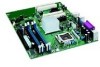
Intel Desktop Board D915PGN/D915PSY Technical Product Specification 1.3.3 Board Layouts Figure 1 shows the location of the major components on the Desktop Board D915PGN. A B D F G HI J K L CE M N O MM LL KK P JJ Q R S II T HH U FF DD BB GG EE CC AA Z Y X WV Figure 1. D915PGN - Intel BOXD915PGNL | Product Specification - Page 15
in card connector K Rear chassis fan connector 1 L Back panel connectors M Alternate power connector N +12V power connector (ATX12V) O LGA775 processor socket P Processor fan connector Q Intel 82915P MCH R DIMM Channel A sockets S Serial port B connector (optional) T DIMM Channel - Intel BOXD915PGNL | Product Specification - Page 16
Intel Desktop Board D915PGN/D915PSY Technical Product Specification Figure 2 shows the location of the major components on the Desktop Board D915PSY. A C E FG H I J BD K L KK M JJ II HH N O P Q GG R S T EE CC AA FF DD BB Z Y X W VU Figure 2. D915PSY Board Components Table 5 lists - Intel BOXD915PGNL | Product Specification - Page 17
Table 5. D915PSY Board Components Shown in Figure 2. Item/callout from Figure 2 Description A ATAPI CD-ROM connector (optional) B PCI Express x1 bus add-in card connectors C Realtek ALC860 audio codec D S/PDIF connector (optional) E Front panel audio connector F PCI Conventional bus add - Intel BOXD915PGNL | Product Specification - Page 18
Intel Desktop Board D915PGN/D915PSY Technical Product Specification 1.3.4 Block Diagram Figure 3 is a block diagram of the major functional areas of the boards. PCI Express x1 Interface DMI Interconnect High Definition Audio Link LAN Connect Interface LPC Bus PCI Express x1 Slot 1 PCI Express x1 - Intel BOXD915PGNL | Product Specification - Page 19
for the Desktop Board D915PSY Processor data sheets ICH6 addressing Custom splash screens Audio software and utilities LAN software and drivers Visit this World Wide Web site: http://www.intel.com/design/motherbd http://support.intel.com/support/motherboards/desktop http://developer.intel.com - Intel BOXD915PGNL | Product Specification - Page 20
Intel Desktop Board D915PGN/D915PSY Technical Product Specification 1.6 System Memory The boards have four DIMM sockets and support the following memory features: • 2.5 V (only) DDR SDRAM DIMMs with gold-plated contacts • Unbuffered, single-sided or double-sided DIMMs with the following restriction - Intel BOXD915PGNL | Product Specification - Page 21
Product Description Table 7 lists the supported DIMM configurations. Table 7. Supported Memory Configurations DIMM Capacity SDRAM Configuration Density SDRAM Organization Front-side/Back-side Number of SDRAM Devices 128 MB SS 256 Mbit 16 M x 16/empty 4 256 - Intel BOXD915PGNL | Product Specification - Page 22
Intel Desktop Board D915PGN/D915PSY Technical Product Specification 1.6.1 Memory Configurations The Intel 82915P MCH supports two types of memory organization: • Dual channel (Interleaved) mode. This mode offers the highest throughput for real world applications. Dual channel mode is enabled when - Intel BOXD915PGNL | Product Specification - Page 23
Product Description 1.6.1.1 Dual Channel (Interleaved) Mode Configurations Figure 5 shows a dual channel configuration using two DIMMs. In this example, the DIMM0 (blue) sockets of both channels are populated with identical DIMMs. 1 GB 1 GB Channel A, DIMM 0 Channel A, DIMM 1 Channel B, DIMM 0 - Intel BOXD915PGNL | Product Specification - Page 24
Intel Desktop Board D915PGN/D915PSY Technical Product Specification Figure 7 shows a dual channel configuration using four DIMMs. In this example, the combined capacity of the two DIMMs in Channel A equal the combined capacity of - Intel BOXD915PGNL | Product Specification - Page 25
Product Description 1.6.1.2 Single Channel (Asymmetric) Mode Configurations ✏ NOTE Dual channel (Interleaved) mode configurations provide the highest memory throughput. Figure 8 shows a single channel configuration using one DIMM. In this example, only the DIMM0 (blue) socket of Channel A is - Intel BOXD915PGNL | Product Specification - Page 26
Intel Desktop Board D915PGN/D915PSY Technical Product Specification 1.7 Intel® 915P Chipset The Intel 915P chipset consists of the following devices: • Intel 82915P Memory Controller Hub (MCH) with Direct Media Interface (DMI) interconnect • Intel 82801FB I/O Controller Hub (ICH6) with DMI - Intel BOXD915PGNL | Product Specification - Page 27
mode to the BIOS. The boards support Laser Servo board The location of the Parallel ATA IDE connector on the D915PSY board XP and Windows 2000 operating systems. ✏ NOTE Many Serial ATA drives use new low-voltage power connectors and require adaptors or power supplies equipped with low-voltage power - Intel BOXD915PGNL | Product Specification - Page 28
Intel Desktop Board D915PGN/D915PSY Technical Product Specification For information about The location of the Serial ATA IDE connectors on the D915PGN board The location of the Serial ATA IDE connectors on the D915PSY board Refer to Figure 18, page 66 Figure 19, page 68 1.7.2.3 SCSI Hard Drive - Intel BOXD915PGNL | Product Specification - Page 29
management, including a programmable wake-up event interface • PCI Conventional bus power management support The BIOS Setup program provides configuration options for the I/O controller. 1.9.1 Serial Ports The Desktop Board can support up to two serial port connectors. Serial port A is located on - Intel BOXD915PGNL | Product Specification - Page 30
Intel Desktop Board D915PGN/D915PSY Technical Product Specification 1.9.4 Keyboard and Mouse Interface PS/2 keyboard and mouse connectors are located on the back panel. ✏ NOTE The keyboard is supported in the bottom PS/2 connector and the mouse is supported in the top PS/2 connector. Power to the - Intel BOXD915PGNL | Product Specification - Page 31
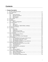
the following: • Intel 82801FB I/O Controller Hub (ICH6) • Realtek ALC860 audio codec • Microphone input that supports a single dynamic, condenser, or electret microphone The front and back audio connectors are configurable through the audio device drivers. The available configurable audio ports are - Intel BOXD915PGNL | Product Specification - Page 32
Intel Desktop Board D915PGN/D915PSY Technical Product Specification Figure 11 is a block diagram of the High Definition audio subsystem. 82801FB I/O Controller Hub (ICH6) Intel High Definition Audio Link ALC860 Audio Codec Mic In/Retasking Jack B Line In/Retasking Jack C Line Out/Retasking Jack - Intel BOXD915PGNL | Product Specification - Page 33
board is powered boards provide the following ASF support for PCI Express x1 bus add-in LAN cards and PCI Conventional bus add-in LAN cards installed in PCI Conventional bus slot 2: • Monitoring of system firmware progress events, including: BIOS present Primary processor initialization Memory - Intel BOXD915PGNL | Product Specification - Page 34
Intel Desktop Board D915PGN/D915PSY Technical Product Specification 1.11.3 LAN Subsystem Software LAN software and drivers are available from Intel's World Wide Web site. For information about Obtaining LAN software and drivers Refer to Section 1.4, page 19 1.11.4 Intel® Wireless Connect - Intel BOXD915PGNL | Product Specification - Page 35
the D915PSY board Product Description 35 - Intel BOXD915PGNL | Product Specification - Page 36
Intel Desktop Board D915PGN/D915PSY Technical Product Specification 1.12.2 Thermal Monitoring Figure 13 shows the location of the sensors and fan connectors for the D915PGN board. 13 3 1 A CB 4 1 D 13 1 3 Item A B C D E F G H HG F E OM17055 Description Thermal diode, located on - Intel BOXD915PGNL | Product Specification - Page 37
Monitoring for D915PSY Board 1.12.3 Fan Monitoring Fan monitoring can be implemented using Intel® Desktop Utilities, LANDesk* software, or thirdparty software. The level of monitoring and control is dependent on the hardware monitoring ASIC used with the Desktop Board. For information about - Intel BOXD915PGNL | Product Specification - Page 38
Intel Desktop Board D915PGN/D915PSY Technical Product Specification 1.12.4 Chassis Intrusion and Detection The boards support a chassis security feature that detects if the chassis cover is removed. The security feature uses a mechanical switch on the chassis that attaches to the chassis - Intel BOXD915PGNL | Product Specification - Page 39
- Soft off) On (ACPI G0 - working state) On (ACPI G0 - working state) Sleep (ACPI G1 - sleeping state) Sleep (ACPI G1 - sleeping state) ...and the power switch is pressed for Less than four seconds Less than four seconds More than four seconds Less than four seconds More than four seconds ...the - Intel BOXD915PGNL | Product Specification - Page 40
Intel Desktop Board D915PGN/D915PSY Technical Product Specification Table 10 lists the power states supported by the boards along with the associated system power targets. See the ACPI specification for a complete description of the various system and power states. Table 10. Power States and - Intel BOXD915PGNL | Product Specification - Page 41
and PME# signal, S5 is disabled by default in the BIOS Setup program. Setting this option to Power On will enable a wake-up event from LAN in the S5 support. In addition, software, drivers, and peripherals must fully support ACPI wake events. 1.13.2 Hardware Support CAUTION Ensure that the power - Intel BOXD915PGNL | Product Specification - Page 42
Intel Desktop Board D915PGN/D915PSY Technical Product Specification Resume on Ring enables telephony devices to access the computer when it is in a power- provides full ACPI support. 1.13.2.1 Power Connector ATX12V-compliant power supplies can turn off the system power through system control. - Intel BOXD915PGNL | Product Specification - Page 43
Specification. Add-in boards that also support this specification can participate in power management and can be used to wake the computer. The use of Instantly Available PC technology requires operating system support and PCI 2.2 compliant add-in cards, PCI Express add-in cards, and drivers - Intel BOXD915PGNL | Product Specification - Page 44
Intel Desktop Board D915PGN/D915PSY Technical Product Specification 1.13.2.6 Wake from USB USB bus activity wakes the computer from ACPI S1 or S3 states. ✏ NOTE Wake from USB requires the use of a USB peripheral that supports PME enabled in BIOS). 1.13.2.9 WAKE# Signal Wake-up Support When the WAKE# - Intel BOXD915PGNL | Product Specification - Page 45
Product Description CR3J1 OM17056 Figure 15. Location of the Standby Power Indicator LED 45 - Intel BOXD915PGNL | Product Specification - Page 46
specifically designed to shield unencrypted keys and platform authentication information from software-based attacks. 1.14.1 System Requirements • Intel Desktop Board D915PGN or D915PSY • Microsoft Windows* 2000 Professional (SP4) or Microsoft Windows XP the motherboard, (via a BIOS switch) to - Intel BOXD915PGNL | Product Specification - Page 47
Product Description 1.14.3 Security Precautions Security, like any other aspect of computer maintenance requires planning. What is unique about security has to do with understanding who "friends" and adversaries are. The TPM provides mechanisms to enable the owner/user to protect their information - Intel BOXD915PGNL | Product Specification - Page 48
Intel Desktop Board D915PGN/D915PSY Technical Product Specification 1.14.3.2 Emergency Recovery File Back Up Procedures The Emergency Recovery Token (SPEmRecToken.xml) must be saved or moved to a removable media (floppy, USB drive, CDR, - Intel BOXD915PGNL | Product Specification - Page 49
use the following steps to enable the TPM. 1. While the PC is displaying the splash screen (or POST screen), press the key to enter BIOS. 2. Use the arrow keys to go to the Advanced Menu, select Peripheral Configuration, and then press the key. 3. Select the Trusted Platform Module - Intel BOXD915PGNL | Product Specification - Page 50
Intel Desktop Board D915PGN/D915PSY Technical Product Specification 15. Follow the instructions and create and document the locations for is not present when a new key is generated, then keys will have to be manually backed up using the Key Transfer Manager when the removable media is available. 19. - Intel BOXD915PGNL | Product Specification - Page 51
damage. Some circuitry on the desktop board can continue to operate even though the front panel power switch is off. CAUTION DATA ENCRYPTED the configuration jumper on the board to pins 2-3. 3. Restore power to the PC and power on. 4. System should automatically enter BIOS setup. 5. Use the arrow - Intel BOXD915PGNL | Product Specification - Page 52
Intel Desktop Board D915PGN/D915PSY Technical Product Specification 1.14.9 Software Support • For assistance with the Infineon Security Platform Software, visit the web at: http://www.infineon.com • For assistance with the Wave System EMBASSY Trust Suite, - Intel BOXD915PGNL | Product Specification - Page 53
Product Description 53 - Intel BOXD915PGNL | Product Specification - Page 54
- Intel BOXD915PGNL | Product Specification - Page 55
2.2.1 Addressable Memory The board utilizes 4 GB of addressable system memory. Typically the address space that is allocated for PCI Conventional bus add-in cards, PCI Express configuration space, BIOS (firmware hub), and chipset overhead resides above the top of DRAM (total system memory). On - Intel BOXD915PGNL | Product Specification - Page 56
Intel Desktop Board D915PGN/D915PSY Technical Product Specification The amount of installed memory that can be used will vary based on add-in cards and BIOS settings. Figure 16 shows a schematic of the system memory map. All installed system memory can be used when there is no overlap of system - Intel BOXD915PGNL | Product Specification - Page 57
(open to the PCI Conventional bus). Dependent on video adapter used. Video memory and BIOS Extended BIOS data (movable by memory manager software) Extended conventional memory Conventional memory 2.3 DMA Channels Table 13. DMA Channels DMA Channel Number 0 1 2 3 4 5 6 7 Data Width 8 or 16 bits - Intel BOXD915PGNL | Product Specification - Page 58
Intel Desktop Board D915PGN/D915PSY Technical Product Specification 2.4 Fixed I/O Map Table 14. I/O Map Address (hex) Size Description 0000 - 00FF 0170 - 0177 256 bytes 8 bytes Used by the Desktop Board D915PGN/D915PSY. Refer to the ICH6 data sheet for dynamic addressing information. - Intel BOXD915PGNL | Product Specification - Page 59
Number (hex) 00 00 00 01 00 00 01 02 Description Memory controller of Intel 82915P component PCI Express x16 graphics port (Note 1) Integrated graphics controller Integrated graphics controller Intel High Definition Audio Controller PCI Express port 1 (PCI Express x1 bus connector 1) PCI Express - Intel BOXD915PGNL | Product Specification - Page 60
Intel Desktop Board D915PGN/D915PSY Technical Product Specification 2.6 Interrupts The interrupts can be routed through either the Programmable Interrupt Controller (PIC) or the Advanced Programmable Interrupt Controller (APIC) portion of the ICH6 component. The PIC is supported in Windows 98 SE - Intel BOXD915PGNL | Product Specification - Page 61
devices. The PCI Conventional specification describes how interrupts can be Conventional interrupt sources are electrically tied together on the board and therefore share the same interrupt. Table 17 already connected to the ICH6 audio controller. The add-in card in PCI Conventional bus - Intel BOXD915PGNL | Product Specification - Page 62
Intel Desktop Board D915PGN/D915PSY Technical Product Specification Table 17. PCI Interrupt Routing Map PCI Interrupt Source IEEE-1394a controller PCI bus connector 1 PCI bus connector 2 PCI bus connector 3 (Note) PCI bus connector 4 (Note) PIRQA INTD Note: Not present on the D915PSY board. - Intel BOXD915PGNL | Product Specification - Page 63
as fans and internal peripherals. Do not use these connectors to power devices external to the computer's chassis. A fault in the load could cause damage to the computer, the power cable, and the external devices themselves. This section describes the board's connectors. The connectors can be divided - Intel BOXD915PGNL | Product Specification - Page 64
Intel Desktop Board D915PGN/D915PSY Technical Product Specification 2.8.1 Back Panel Connectors Figure 17 shows the Figure 17. ✏ NOTE The back panel audio line out connector is designed to power headphones or amplified speakers only. Poor audio quality occurs if passive (non-amplified) speakers - Intel BOXD915PGNL | Product Specification - Page 65
17 Description A PS/2 mouse port (Green) B PS/2 keyboard port (Purple) C Parallel port (Burgundy) D Serial port A (Teal) E Audio line in/Retasking Port C (Light blue) F Audio line out/Retasking Port D (Lime Green) G Mic in/Retasking Port B (Pink) H IEEE-1394a (optional) I USB ports - Intel BOXD915PGNL | Product Specification - Page 66
Intel Desktop Board D915PGN/D915PSY Technical Product Specification 2.8.2 Component-side Connectors Figure 18 shows the locations of the component-side connectors on the D915PGN board. B D FH J L AC E GI K M N P O 13 12 9 10 3 4 1 1 2 1 10 12 10 1 3 1 4 4 13 12 10 11 1 3 9 1 11 - Intel BOXD915PGNL | Product Specification - Page 67
add-in card connector 1 G S/PDIF connector (optional) H Front panel audio connector I PCI Conventional bus add-in card connector 2 J Front panel IEEE connector 2 BB Serial ATA connector 0 CC Auxiliary front panel power LED connector DD Front panel connector EE ATX fan connector ( - Intel BOXD915PGNL | Product Specification - Page 68
Intel Desktop Board D915PGN/D915PSY Technical Product Specification Figure 19 shows the locations of the component-side connectors on the D915PSY board. BD AC E F G I H BB AA 12 9 10 3 4 1 1 1 3 1 44 13 12 10 11 2 1 10 12 10 Z 9 1 11 2 1 1 3 4 J 1 12 Y 10 X W 1 2 1 VT R P US Q - Intel BOXD915PGNL | Product Specification - Page 69
from Figure 19 Description A S/PDIF connector (optional) B Front panel audio connector C PCI Conventional bus add-in card connector 2 D Front panel connector 2 U Serial ATA connector 0 V Auxiliary front panel power LED connector W Front panel connector X Front panel USB connector - Intel BOXD915PGNL | Product Specification - Page 70
Intel Desktop Board D915PGN/D915PSY Technical Product Specification Table 21. S/PDIF Connector (Optional) Pin Signal Name 1 +5 V 2 S/PDIF Output 3 Ground Table 22. ATAPI CD-ROM Connector (Optional) Pin Signal Name 1 Left audio input from CD-ROM 2 CD audio differential ground 3 CD - Intel BOXD915PGNL | Product Specification - Page 71
three standard and one optional chassis fan connectors: • Front chassis fan • Rear chassis fan 1 • Rear chassis fan 2 • ATX fan connector (optional) The D915PSY board has two chassis fan connectors: • Front chassis fan • Rear chassis fan Table 29 lists the signal names for the chassis fan connectors - Intel BOXD915PGNL | Product Specification - Page 72
Intel Desktop Board D915PGN/D915PSY Technical Product Specification 2.8.2.2 Power Supply Connectors The board has three power supply connectors: • Main power - a 2 x 12 connector. This connector is compatible with 2 x 10 connectors previously used on Intel Desktop boards. The board supports the use - Intel BOXD915PGNL | Product Specification - Page 73
connectors; the D915PSY board has two PCI Conventional add-in card connectors. The SMBus is routed to PCI Conventional bus connector 2 only (ATX expansion slot 6). PCI Conventional bus add-in cards with SMBus support can access sensor data and other information residing on the Desktop Board. Note - Intel BOXD915PGNL | Product Specification - Page 74
Intel Desktop Board D915PGN/D915PSY Technical Product Specification 2.8.2.5 Front Panel Connector This [Purple] 5 Ground Ground 6 7 FP_RESET# In Reset switch 8 Power 9 +5 V Power 10 Signal In/Out Description Power LED [Green] HDR_BLNK_ Out GRN Front panel green LED HDR_BLNK_ Out - Intel BOXD915PGNL | Product Specification - Page 75
that is normally open. When the switch is closed, the board resets and runs the POST. 2.8.2.5.3 Power/Sleep LED Connector [Green] Pins 2 and 4 [Green or customer-specific. 2.8.2.5.4 Power Switch Connector [Red] Pins 6 and 8 [Red] can be connected to a front panel momentary-contact power switch. The - Intel BOXD915PGNL | Product Specification - Page 76
Intel Desktop Board D915PGN/D915PSY Technical Product Specification Power (+5 V DC) One D− USB Port D+ Ground Key (no pin) 1 2 3 4 5 6 7 8 10 Power (+5 V DC) D− One USB D+ Port Ground No Connect OM15963 Figure 21. Connection Diagram for Front Panel USB Connectors 2.8.2.7 - Intel BOXD915PGNL | Product Specification - Page 77
the power and unplug the power cord from the computer before changing a jumper setting. Otherwise, the board could be damaged. Figure 23 shows the location of the jumper block on the D915PGN board. (The jumper is in the same location on the D915PSY board.) The jumper block determines the BIOS Setup - Intel BOXD915PGNL | Product Specification - Page 78
Intel Desktop Board D915PGN/D915PSY Technical Product Specification 2.10 Mechanical Considerations 2.10.1 D915PGN Board Form Factor The D915PGN board is designed to fit into an ATX-form-factor chassis. Figure 24 illustrates the mechanical form factor of the board. Dimensions are given in inches [ - Intel BOXD915PGNL | Product Specification - Page 79
the I/O connectors and mounting holes are in compliance with the ATX specification. 6.500 [165.10] 6.100 [154.94] 1.800 [45.72] 5.200 [132.08] 0.00 2.850 [72.39] 3.100 [78.74] 3.150 [80.01] 2.600 [66.04] 0.00 6.450 6.200 [163.83] [157.48] Figure 25. D915PSY Board Dimensions OM17064 79 - Intel BOXD915PGNL | Product Specification - Page 80
Intel Desktop Board D915PGN/D915PSY Technical Product Specification 2.10.3 I/O Shield The back panel I/O shield for the boards must meet specific dimension and material requirements. Systems based on these boards need the back panel I/O shield to pass certification testing. Figure 26 shows the I/O - Intel BOXD915PGNL | Product Specification - Page 81
mA current draw per USB port. These calculations are not based on specific processor values or memory configurations but are based on the minimum and maximum current draw possible from the board's power delivery subsystems to the processor, memory, and USB ports. Use the datasheets for add-in cards - Intel BOXD915PGNL | Product Specification - Page 82
Intel Desktop Board D915PGN/D915PSY Technical Product Specification 2.11.3 Fan Connector Current Capability supported and manufacturing options. System integrators should refer to the power usage values listed in Table 38 when selecting a power supply for use with the board. Additional power - Intel BOXD915PGNL | Product Specification - Page 83
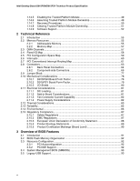
processor and/or voltage regulator or, in some instances, damage to the board. For a list of chassis that have been tested with Intel desktop boards please refer to the following website: http://developer.intel.com/design/motherbd/cooling.htm All responsibility for determining the adequacy of any - Intel BOXD915PGNL | Product Specification - Page 84
Intel Desktop Board D915PGN/D915PSY Technical Product Specification CAUTION Ensure that proper airflow is maintained in zones. A B D C Item A B C D Description Processor voltage regulator area Processor Intel 82915P MCH Intel 82801FB ICH6 Figure 28. Localized High Temperature Zones OM17063 84 - Intel BOXD915PGNL | Product Specification - Page 85
board. Table 40. Thermal Considerations for Components Component Intel Pentium 4 processor Intel 82915P MCH Intel 82801FB ICH6 Maximum Case Temperature For processor case temperature, see processor datasheets and processor specification MTBF for the D915PGN and D915PSY boards is 102,038 hours. 85 - Intel BOXD915PGNL | Product Specification - Page 86
Intel Desktop Board D915PGN/D915PSY Technical Product Specification 2.14 Environmental Table 41 lists the environmental specifications for the board. Table 41. Environmental Specifications Parameter Temperature Non-Operating Operating Shock Unpackaged Packaged Vibration Unpackaged Packaged - Intel BOXD915PGNL | Product Specification - Page 87
Technology Equipment - Safety - Part 1: General Requirements (International) 2.15.2 EMC Regulations Table 43 lists the EMC regulations the Desktop Boards D915PGN and D915PSY comply with when correctly installed in a compatible host system. Table 43. EMC Regulations Regulation FCC (Class B) ICES - Intel BOXD915PGNL | Product Specification - Page 88
Intel Desktop Board D915PGN/D915PSY Technical Product Specification 2.15.2.1 FCC Compliance Statement (USA) Product Type: D915PGN Desktop Board and D915PSY Desktop Board , if not installed and used in accordance with the instructions, may cause harmful interference to radio communications. However, - Intel BOXD915PGNL | Product Specification - Page 89
be regulated upon disposal: lead solder on the printed wiring board assembly. 2.15.4.2 Recycling Considerations Intel encourages its customers to recycle its products and their components (e.g., batteries, circuit boards, plastic enclosures, etc.) whenever possible. In the U.S., a list of recyclers - Intel BOXD915PGNL | Product Specification - Page 90
Intel Desktop Board D915PGN/D915PSY Technical Product Specification 2.15.5 Product Certification Markings (Board Level) Table 44 lists the board's product certification markings. Table 44. Product Certification Markings Description UL joint US/Canada Recognized Component mark. Includes adjacent UL - Intel BOXD915PGNL | Product Specification - Page 91
3.2 BIOS Flash Memory Organization 92 3.3 Resource Configuration 92 3.4 System Management BIOS (SMBIOS 93 3.5 Legacy USB Support...93 3.6 BIOS Updates ...94 3.7 Boot Options ...95 3.8 Fast Booting Systems with Intel® Rapid BIOS Boot 96 3.9 BIOS Security Features 97 3.1 Introduction The boards - Intel BOXD915PGNL | Product Specification - Page 92
Intel Desktop Board D915PGN/D915PSY Technical Product Specification Table 45 lists the BIOS Setup program menu features. Table 45. BIOS Setup Program Menu Bar Maintenance Main Advanced Security Clears passwords and displays processor information Displays processor and memory configuration - Intel BOXD915PGNL | Product Specification - Page 93
USB drivers are not yet available. Legacy USB support is used to access the BIOS Setup program, and to install an operating system that supports USB. By default, Legacy USB support is set to Enabled. Legacy USB support operates as follows: 1. When you apply power to the computer, legacy support is - Intel BOXD915PGNL | Product Specification - Page 94
Intel Desktop Board D915PGN/D915PSY Technical Product Specification 5. The operating system loads. While the that supports USB, verify that Legacy USB support in the BIOS Setup program is set to Enabled and follow the operating system's installation instructions. 3.6 BIOS Updates The BIOS can - Intel BOXD915PGNL | Product Specification - Page 95
from CD-ROM is supported in compliance to the El Torito bootable CD-ROM format specification. Under the Boot menu in the BIOS Setup program, ATAPI CD drive. 3.7.2 Network Boot The network can be selected as a boot device. This selection allows booting from the onboard LAN or a network add-in card - Intel BOXD915PGNL | Product Specification - Page 96
Intel Desktop Board D915PGN/D915PSY Technical Product Specification 3.8 Fast Booting Systems with Intel® Rapid BIOS Boot These factors affect system boot speed: • Selecting and configuring peripherals properly • Using an optimized BIOS, such as the Intel® Rapid BIOS 3.8.1 Peripheral Selection and - Intel BOXD915PGNL | Product Specification - Page 97
Setup program. This is the user mode. • If only the supervisor password is set, pressing the key at the password prompt of the BIOS Setup program allows the user restricted access to Setup. • If both the supervisor and user passwords are set, users can enter either the supervisor password - Intel BOXD915PGNL | Product Specification - Page 98
Intel Desktop Board D915PGN/D915PSY Technical Product Specification 98 - Intel BOXD915PGNL | Product Specification - Page 99
BIOS Beep Codes...106 4.1 BIOS Error Messages Table 49 lists the error messages and provides a brief description of each. Table 49. BIOS drive. An error occurred when testing L2 cache. Cache memory may be bad. The battery may be losing power. Replace the battery soon. The display type is - Intel BOXD915PGNL | Product Specification - Page 100
Intel Desktop Board D915PGN/D915PSY Technical Product Specification Table 49. BIOS Error memory was removed then memory may be bad. Memory Size Increased Memory size has increased since the last boot. If no memory was added there may be a problem with the system. Memory Size Changed Memory - Intel BOXD915PGNL | Product Specification - Page 101
for recovery else go to check point D7 for giving control to main BIOS. Find Main BIOS module in ROM image. Uncompress the main BIOS module. Copy main BIOS image to F000 shadow RAM and give control to main BIOS in F000 shadow RAM. Table 51. Boot Block Recovery Code Checkpoints Code E0 E8 E9 EA EB - Intel BOXD915PGNL | Product Specification - Page 102
Intel Desktop Board D915PGN/D915PSY Technical Product Specification Table 52. Runtime Code Uncompressed in F000 Shadow RAM power-on. BIOS stack set. Going to disable cache if any. POST code to be uncompressed. CPU init and CPU start. About to start memory refresh test. Memory Refresh line is toggling - Intel BOXD915PGNL | Product Specification - Page 103
Going to find out amount of memory below 1M memory. Amount of memory below 1M found and verified. Going to find out amount of memory above 1M memory. Amount of memory above 1M found and verified. Check for soft reset and going to clear memory below 1M for soft reset. (If power on, go to check point - Intel BOXD915PGNL | Product Specification - Page 104
Intel Desktop Board D915PGN/D915PSY Technical Product Specification Table 52. Runtime Code Uncompressed in F000 Shadow RAM for memory size mismatch with CMOS. Memory size check power-on screen message. First screen message displayed. message displayed. PS/2 Mouse check and extended BIOS - Intel BOXD915PGNL | Product Specification - Page 105
form the runtime SMBIOS image in shadow. Going to copy any code to specific area. Copying of code to specific area done. Going to give control to INT-19 boot loader. 4.3 Bus Initialization Checkpoints The system BIOS gives control to the different buses at several checkpoints to do various tasks - Intel BOXD915PGNL | Product Specification - Page 106
Intel Desktop Board D915PGN/D915PSY Technical Product Specification Table 55 describes the lower nibble of the completes normally, the BIOS issues one short beep before passing control to the operating system. Table 56. Beep Codes Beep 1 3 6 7 8 Description CPU error Memory error System failure - Intel BOXD915PGNL | Product Specification - Page 107
Error Messages and Beep Codes 107
-
 1
1 -
 2
2 -
 3
3 -
 4
4 -
 5
5 -
 6
6 -
 7
7 -
8
-
9
-
10
-
11
-
12
-
13
-
14
-
15
-
16
-
17
-
18
-
19
-
20
-
21
-
22
-
23
-
24
-
25
-
26
-
27
-
28
-
29
-
30
-
31
-
32
-
33
-
34
-
35
-
36
-
37
-
38
-
39
-
40
-
41
-
42
-
43
-
44
-
45
-
46
-
47
-
48
-
49
-
50
-
51
-
52
-
53
-
54
-
55
-
56
-
57
-
58
-
59
-
60
-
61
-
62
-
63
-
64
-
65
-
66
-
67
-
68
-
69
-
70
-
71
-
72
-
73
-
74
-
75
-
76
-
77
-
78
-
79
-
80
-
81
-
82
-
83
-
84
-
85
-
86
-
87
-
88
-
89
-
90
-
91
-
92
-
93
-
94
-
95
-
96
-
97
-
98
-
99
-
100
-
101
-
102
-
103
-
104
-
105
-
106
-
107
 |
 |

Intel
®
Desktop Boards
D915PGN/D915PSY
Technical Product Specification
June 2004
Order Number:
C68598-001
The Intel
®
Desktop Board D915PGN/D915PSY may contain design defects or errors known as errata that may cause the product to deviate from published specifications.
Current
characterized errata are documented in the Intel Desktop Board D915PGN/D915PSY Specification Update.