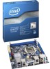
Intel BOXDH67CF Product Specification
Intel BOXDH67CF Manual
 |
View all Intel BOXDH67CF manuals
Add to My Manuals
Save this manual to your list of manuals |
Intel BOXDH67CF manual content summary:
- Intel BOXDH67CF | Product Specification - Page 1
April 2012 Order Number: G15488-002 The Intel Desktop Board DH67CF may contain design defects or errors known as errata that may cause the product to deviate from published specifications. Current characterized errata are documented in the Intel Desktop Board DH67CF Specification Update. - Intel BOXDH67CF | Product Specification - Page 2
supported without further evaluation by Intel. Intel Corporation or instructions marked "reserved" or "undefined." Intel Intel sales office or your distributor to obtain the latest specifications before placing your product order. Intel, Core i7, and Core i5 are trademarks of Intel Corporation - Intel BOXDH67CF | Product Specification - Page 3
label on the component side of the board. 2. The Intel® 82H67 PCH Express Chipset used on this AA revision consists Spec Numbers SLH82 SLJ49 Errata Current characterized errata, if any, are documented in a separate Specification Update. See http://developer.intel.com/products/desktop/motherboard - Intel BOXDH67CF | Product Specification - Page 4
Intel Desktop Board DH67CF Technical Product Specification iv - Intel BOXDH67CF | Product Specification - Page 5
audiences. What This Document Contains Chapter 1 2 3 4 5 Description A description of the hardware used on Intel Desktop Board DH67CF A map of the resources of the Intel Desktop Board The features supported by the BIOS Setup program A description of the BIOS error messages, beep codes, and POST - Intel BOXDH67CF | Product Specification - Page 6
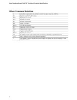
Intel Desktop Board DH67CF Technical Product Specification Other Common Notation # GB GB/s Gb/s KB Kbit kbits/s MB MB/s Mbit Mbits/s xxh x.x V * Used after a signal name to - Intel BOXDH67CF | Product Specification - Page 7
Layout 13 1.1.3 Block Diagram 15 1.2 Legacy Considerations 16 1.3 Online Support 16 1.4 Processor 17 1.4.1 PCI Express x16 Graphics 17 1.5 System Memory 18 1.5.1 Memory Configurations 19 1.6 Intel® H67 Express Chipset 21 1.7 Graphics Subsystem 21 1.7.1 Integrated Graphics 21 1.7.2 USB - Intel BOXDH67CF | Product Specification - Page 8
Intel Desktop Board DH67CF Technical Product Specification 1.14 Power Management 33 1.14.1 ACPI 33 1.14.2 Hardware Support 35 2 Technical Reference 2.1 Memory Resources 41 2.1.1 Addressable Memory 41 2.1.2 Memory Map 43 2.2 Connectors and Headers 43 2.2.1 Back Panel Connectors 44 2.2.2 - Intel BOXDH67CF | Product Specification - Page 9
Summary 11 2. Components Shown in Figure 1 14 3. Supported Memory Configurations 18 4. HDMI Port Status Conditions 22 5. DVI Port Status side Connectors and Headers Shown in Figure 10 46 13. Front Panel Audio Header for Intel HD Audio 47 14. Front Panel Audio Header for AC '97 Audio 47 15. - Intel BOXDH67CF | Product Specification - Page 10
Intel Desktop Board DH67CF Technical Product Specification 18. Chassis Intrusion Header 48 19. Processor and System (4-Pin) Fan Headers 48 20. Back Panel CIR Emitter (Output) Header 48 21. Front Panel CIR Receiver (Input) Header 48 22. Processor Core Power Connector 49 23. Main Power Connector - Intel BOXDH67CF | Product Specification - Page 11
Mini-ITX (6.7 inches by 6.7 inches [170.18 millimeters by 170.18 millimeters]) • Intel® Core™ i7, Intel® Core™ i5, and Intel Core™ i3 processors with up to 65W TDP in an LGA1155 socket ― One PCI Express* 2.0 x16 graphics interface ― Integrated memory controller with dual channel DDR3 memory support - Intel BOXDH67CF | Product Specification - Page 12
headers • Two SATA 6.0 Gb/s interfaces through Intel H67 Express Chipset with Intel® Rapid Storage Technology RAID support (blue) • Three Serial ATA (SATA) 3.0 Gb/s interfaces through Intel H67 Express Chipset with Intel Rapid Storage Technology RAID support: ― One internal SATA ports (black) ― One - Intel BOXDH67CF | Product Specification - Page 13
Product Description 1.1.2 Board Layout Figure 1 shows the location of the major components on Intel Desktop Board DH67CF. Figure 1. Major Board Components 13 - Intel BOXDH67CF | Product Specification - Page 14
Item/callout from Figure 1 A B C D E F G H I J K L M N O P Q R S T U V W X Y Z Description Back panel connectors Processor core power connector (2 x 2) Front panel USB 2.0 header BIOS Setup configuration jumper block SATA connectors Intel H67 Express Chipset Front panel USB 2.0 header Front panel - Intel BOXDH67CF | Product Specification - Page 15
Product Description 1.1.3 Block Diagram Figure 2 is a block diagram of the major functional areas of the board. Figure 2. Block Diagram 15 - Intel BOXDH67CF | Product Specification - Page 16
Board DH67CF Visit this World Wide Web site: http://www.intel.com/products/motherboard/index.htm http://www.intel.com/p/en_US/support?iid=hdr+support http://ark.intel.com Supported processors Chipset information BIOS and driver updates Tested memory Integration information http://processormatch - Intel BOXDH67CF | Product Specification - Page 17
board is designed to support the Intel Core i7, Intel Core i5, and Intel Core i3 processors in an LGA1155 socket. Other processors may be supported in the future. This board is designed to support processors with a maximum wattage of 65 W Thermal Design Power (TDP). The processors listed above are - Intel BOXDH67CF | Product Specification - Page 18
to support higher performance DDR3 SDRAM DIMMs. • Support for 1.35V Low Voltage DDR3 (new JEDEC specification) • Two independent memory channels with interleaved mode support • information about... Tested Memory Refer to: http://support.intel.com/support/motherboards/desktop/sb /CS-025414.htm 18 - Intel BOXDH67CF | Product Specification - Page 19
Product Description 1.5.1 Memory Configurations The Intel Core i7, Intel Core i5, and Intel Core i3 processors in the LGA1155 socket support the following types of memory organization ... Memory Configuration Examples Refer to: http://www.intel.com/support/motherboards/desktop/sb/cs011965.htm 19 - Intel BOXDH67CF | Product Specification - Page 20
Board DH67CF Technical Product Specification Figure 3 illustrates the memory channel and DIMM configuration. Figure 3. Memory Channel and DIMM Configuration NOTE The Intel Core i7, Intel Core i5, and Intel Core i3 processors require memory to be populated in the DIMM 1 (Channel A, DIMM 1) socket. 20 - Intel BOXDH67CF | Product Specification - Page 21
in graphics card. 1.7.1 Integrated Graphics The board supports integrated graphics through the Intel® Flexible Display Interface (Intel® FDI) for processors with Intel Graphics Technology. NOTE If using a processor with integrated graphics, the board will support only two of the integrated graphics - Intel BOXDH67CF | Product Specification - Page 22
Intel Desktop Board DH67CF Technical Product Specification ⎯ Dynamic Video Memory Technology (DVMT) 5.0 support ⎯ Support of up to 1.7 GB Video Memory with 4 GB and above system memory configuration 1.7.1.2 High Definition Multimedia Interface* (HDMI*) The HDMI port supports standard, enhanced, or - Intel BOXDH67CF | Product Specification - Page 23
resolution is 2560 x 1600 at 60 Hz refresh with a 16:10 aspect ratio (WQXGA). DisplayPort 1.1 adds support for High Bandwidth Digital Content Protection (HDCP) version 1.3. HDCP support enables viewing of protected content from Blu-ray Disc* and HD-DVD optical media over DisplayPort 1.1 connections - Intel BOXDH67CF | Product Specification - Page 24
Desktop Board DH67CF Technical Product Specification 1.7.2 USB The board supports up to 10 USB 2.0 ports and two USB 3.0 ports. The Intel H67 Express Chipset provides the USB controller for the 2.0 ports. The two USB 3.0 ports are provided by the NEC UPD720200 controller. The port arrangement is - Intel BOXDH67CF | Product Specification - Page 25
RAID The board supports Intel Rapid Storage Technology which provides the following RAID (Redundant Array of Independent Drives) levels via the Intel H67 Express Chipset: the RAID drivers. See your Microsoft Windows XP documentation for more information about installing drivers during installation. - Intel BOXDH67CF | Product Specification - Page 26
with Microsoft Consumer Infrared usage models. Microsoft Windows Vista and Microsoft Windows 7 are the supported operating systems. The CIR feature is made up of two separate pieces: the receiving or create their own interface modules to connect to Intel Desktop Boards for this feature to work. 26 - Intel BOXDH67CF | Product Specification - Page 27
information about Obtaining audio software and drivers Refer to Section 1.3, page 16 1.11.2 Audio Subsystem Components The audio subsystem includes the following components: • Intel H67 Express Chipset • Realtek ALC892 audio codec • Front panel audio header that supports Intel HD audio and AC '97 - Intel BOXDH67CF | Product Specification - Page 28
Intel Desktop Board DH67CF Technical Product Specification The back panel audio connectors are configurable through the audio device drivers. The available configurable back panel audio connectors are shown in Figure 4. Item A B C D E F Description Rear surround Center channel and LFE (subwoofer) - Intel BOXDH67CF | Product Specification - Page 29
subsystem consists of the following: • Intel 82579V Gigabit Ethernet Controller (10/100/1000 Mbits/s) • Intel H67 Express Chipset • RJ-45 LAN drivers Refer to http://downloadcenter.intel.com 1.12.1 Intel® 82579V Gigabit Ethernet Controller The Intel 82579V Gigabit Ethernet Controller supports - Intel BOXDH67CF | Product Specification - Page 30
DH67CF Technical Product Specification 1.12.2 LAN Subsystem Software LAN software and drivers are available from Intel's World Wide Web site. For information about Obtaining LAN software and drivers Refer to http://downloadcenter.intel.com 1.12.3 RJ-45 LAN Connector with Integrated LEDs Two LEDs - Intel BOXDH67CF | Product Specification - Page 31
W83677HG-i device, which supports the following: • Processor and system ambient temperature Intel® Desktop Utilities or third-party software. For information about The functions of the fan headers Refer to Section 1.14.2.2, page 36 1.13.3 Chassis Intrusion and Detection The board supports - Intel BOXDH67CF | Product Specification - Page 32
locations of the thermal sensors and fan headers. Item A B C D E F Description Thermal diode, located on the Intel H67 PCH Remote thermal diode 1 Processor fan header Thermal diode, located on the processor die Remote thermal diode 2 System fan header Figure 6. Thermal Sensors and Fan Headers 32 - Intel BOXDH67CF | Product Specification - Page 33
of ACPI with this board requires an operating system that provides full ACPI support. ACPI features include: • Plug and Play (including bus and device , add-in boards (some add-in boards may require an ACPI-aware driver), video displays, and hard disk drives • Methods for achieving less than - Intel BOXDH67CF | Product Specification - Page 34
Intel . Table 10 lists the power states supported by the board along with the associated and Targeted System Power Global States Sleeping States Processor States Device States Targeted System Power (Note external source. No power to the system. Service can be performed safely. Notes: 1. Total - Intel BOXDH67CF | Product Specification - Page 35
these wake-up events from an ACPI state requires an operating system that provides full ACPI support. In addition, software, drivers, and peripherals must fully support ACPI wake events. 1.14.2 Hardware Support CAUTION Ensure that the power supply provides adequate +5 V standby current if LAN wake - Intel BOXDH67CF | Product Specification - Page 36
Intel Desktop Board DH67CF Technical Product Specification NOTE The use of Wake from USB from an ACPI state requires an operating system that provides full ACPI support. 1.14.2.1 Power Connector ATX12V-compliant power supplies can turn off the system power through system control. When an ACPI- - Intel BOXDH67CF | Product Specification - Page 37
a wake-up signal that powers up the computer. Depending on the LAN implementation, the board supports LAN wake capabilities with ACPI in the following ways: • The PCI Express WAKE# signal Instantly Available PC technology requires operating system support and PCI Express add-in cards and drivers. 37 - Intel BOXDH67CF | Product Specification - Page 38
Intel Desktop Board DH67CF Technical Product Specification 1.14.2.5 Wake from USB USB bus activity wakes the computer from an ACPI S3 state. NOTE Wake from USB requires the use of a USB peripheral that supports Wake from USB. 1.14.2.6 WAKE# Signal Wake-up Support When the WAKE# signal on the PCI - Intel BOXDH67CF | Product Specification - Page 39
Product Description 1.14.2.9 +5 V Standby Power Indicator LED The +5 V standby power indicator LED shows that power is still present even when the computer appears to be off. Figure 7 shows the location of the standby power LED. CAUTION If AC power has been switched off and the standby power - Intel BOXDH67CF | Product Specification - Page 40
Intel Desktop Board DH67CF Technical Product Specification 40 - Intel BOXDH67CF | Product Specification - Page 41
2 Technical Reference 2.1 Memory Resources 2.1.1 Addressable Memory The board utilizes 16 GB of addressable system memory. Typically the address space that is allocated for PCI Conventional bus add-in cards, PCI Express configuration space, BIOS (SPI Flash device), and chipset overhead resides above - Intel BOXDH67CF | Product Specification - Page 42
Intel Desktop Board DH67CF Technical Product Specification Figure 8. Detailed System Memory Address Map 42 - Intel BOXDH67CF | Product Specification - Page 43
Technical Reference 2.1.2 Memory Map Table 12 lists the system memory map. Table 12. System Memory Map Address Range (decimal) Address Range (hex) 1024 K - 16777216K K 100000 - 400000000 960 K - 1024 K F0000 - FFFFF 896 K - 960 K E0000 - EFFFF 800 K - 896 K C8000 - DFFFF 640 K - 800 K - Intel BOXDH67CF | Product Specification - Page 44
Intel Desktop Board DH67CF Technical Product Specification 2.2.1 Back Panel Connectors Figure 9 shows the location of the back panel connectors for the board. Item A B C D E F G H I J K L M N Description LAN port - Intel BOXDH67CF | Product Specification - Page 45
Technical Reference 2.2.2 Component-side Connectors and Headers Figure 10 shows the locations of the component-side connectors and headers. Figure 10. Component-side Connectors and Headers 45 - Intel BOXDH67CF | Product Specification - Page 46
Intel Desktop Board DH67CF Technical Product Specification Table 13 lists the component-side connectors and headers identified in Figure 10. Table 13. Component-side Connectors and Headers Shown in Figure 10 Item/callout from Figure 10 Description A Processor core power connector (2 x 2) B - Intel BOXDH67CF | Product Specification - Page 47
Technical Reference 2.2.2.1 Signal Tables for the Connectors and Headers Table 14. Front Panel Audio Header for Intel HD Audio Pin Signal Name Pin Signal Name 1 [Port 1] Left channel 3 [Port 1] Right channel 5 [Port 2] Right channel 7 SENSE_SEND (Jack detection) 9 [Port 2] Left - Intel BOXDH67CF | Product Specification - Page 48
Intel Desktop Board DH67CF Technical Product Specification Table 18. S/PDIF Header Pin Signal Name 1 Ground 2 S/PDIF out 3 Key (no pin) 4 +5 V DC Table 19. Chassis Intrusion Header Pin Signal Name 1 Intruder# 2 Ground Table 20. Processor and System (4-Pin) Fan Headers Pin 1 2 3 4 - Intel BOXDH67CF | Product Specification - Page 49
. The board supports the use of ATX12V power supplies with either 2 x 10 or 2 x 12 main power cables. When using a power supply with a 2 x 10 main power cable, attach that cable on the leftmost pins of the main power connector, leaving pins 11, 12, 23, and 24 unconnected. • Processor core power - Intel BOXDH67CF | Product Specification - Page 50
Intel Desktop Board DH67CF Technical Product Specification 2.2.2.4 Front Panel Header This section describes the functions of the front panel header. Table 25 lists the signal names - Intel BOXDH67CF | Product Specification - Page 51
Technical Reference 2.2.2.4.3 Power/Sleep LED Header Pins 2 and 4 can be connected to a one- or two-color LED. Table 26 shows the possible states for a one-color LED. Table 27 shows the possible states for a two-color LED. Table 26. States for a One-Color Power LED LED State Description Off - Intel BOXDH67CF | Product Specification - Page 52
Intel Desktop Board DH67CF Technical Product Specification 2.2.2.6 Front Panel USB 2.0 Headers Figure 12 is a connection diagram for the front panel USB 2.0 headers. NOTE • The +5 V DC power - Intel BOXDH67CF | Product Specification - Page 53
the three modes: normal, configure, and recovery. When the jumper is set to configure mode and the computer is powered-up, the BIOS compares the processor version and the microcode version in the BIOS and reports if the two match. Figure 13. Location of the Jumper Block 53 - Intel BOXDH67CF | Product Specification - Page 54
Intel Desktop Board DH67CF Technical Product Specification Table 30. BIOS Setup Configuration Jumper Settings Function/Mode Normal Jumper Setting 1-2 Configuration The BIOS uses current configuration information - Intel BOXDH67CF | Product Specification - Page 55
Technical Reference 2.4 Mechanical Considerations 2.4.1 Form Factor The board is designed to fit into a Mini-ITX form-factor chassis. Figure 14 illustrates the mechanical form factor for the board. Dimensions are given in inches [millimeters]. The outer dimensions are 6.7 inches by 6.7 - Intel BOXDH67CF | Product Specification - Page 56
for a system consisting of a supported 65 W processor (see Section 1.4 on page 17 for a list of supported processors), 1 GB DDR3 RAM, one high end video For information about Selecting an appropriate power supply Refer to http://support.intel.com/support/motherboards/desktop/sb /CS-026472.htm 56 - Intel BOXDH67CF | Product Specification - Page 57
headers. Table 32. Fan Header Current Capability Fan Header Maximum Available Current Processor fan System fan 2.0 A 1.5 A 2.5.3 Add-in Board Considerations The with the reader. Intel makes no warranties or representations that merely following the instructions presented in this document - Intel BOXDH67CF | Product Specification - Page 58
) can reach a temperature of up to 120 oC in an open chassis. Figure 15 shows the locations of the localized high temperature zones. Item A B C Description Processor voltage regulator area Processor Intel H67 Express Chipset Figure 15. Localized High Temperature Zones 58 - Intel BOXDH67CF | Product Specification - Page 59
cool the board. Table 33. Thermal Considerations for Components Component Maximum Case Temperature Processor For processor case temperature, see processor datasheets and processor specification updates Intel H67 Express Chipset 104 oC To ensure functionality and reliability, the component is - Intel BOXDH67CF | Product Specification - Page 60
Intel Desktop Board DH67CF Technical Product Specification 2.7 Reliability The Mean Time Between Failures (MTBF) prediction is calculated using component and subassembly random failure rates. The calculation - Intel BOXDH67CF | Product Specification - Page 61
The board uses an Intel BIOS that is stored in the Serial Peripheral Interface Flash Memory (SPI Flash) and can be updated using a disk-based program. The SPI Flash contains the BIOS Setup program, POST, the PCI auto-configuration utility, LAN EEPROM information, and Plug and Play support. The BIOS - Intel BOXDH67CF | Product Specification - Page 62
Intel Desktop Board DH67CF Technical Product Specification Table 36 lists the BIOS Setup program menu features. Table 36. BIOS Setup Program Menu Bar Maintenance Main Configura- tion Performance Clears passwords and displays processor information Displays processor and memory configuration - Intel BOXDH67CF | Product Specification - Page 63
size, cache size, and processor speed • Dynamic data, supports an SMBIOS table interface for such operating systems. Using this support, an SMBIOS service Support Legacy USB support enables USB devices to be used even when the operating system's USB drivers are not yet available. Legacy USB support - Intel BOXDH67CF | Product Specification - Page 64
to prevent accidentally installing an incompatible BIOS. NOTE Review the instructions distributed with the upgrade utility before attempting a BIOS update. For information about BIOS update utilities Refer to http://support.intel.com/support/motherboards/desktop/sb /CS-022312.htm. 3.5.1 Language - Intel BOXDH67CF | Product Specification - Page 65
, for example) Yes USB diskette drive (with a 1.44 MB diskette) No USB hard disk drive No For information about BIOS recovery Refer to http://www.intel.com/support/motherboards/desktop/sb/ cs-023360.htm 65 - Intel BOXDH67CF | Product Specification - Page 66
Intel Desktop Board DH67CF Technical Product Specification 3.7 Boot Options In the BIOS removable drive third, and the network fourth. 3.7.1 Optical Drive Boot Booting from the optical drive is supported in compliance to the El Torito bootable CD-ROM format specification. Under the Boot menu in the - Intel BOXDH67CF | Product Specification - Page 67
of option ROM boot time. NOTE It is possible to optimize the boot process to the point where the system boots so quickly that the Intel logo screen (or a custom logo splash screen) will not be seen. Monitors and hard disk drives with minimum initialization times can also contribute to a boot - Intel BOXDH67CF | Product Specification - Page 68
Intel Desktop Board DH67CF Technical Product Specification 3.9 BIOS Security Features The BIOS includes security features that restrict access to the BIOS Setup program and who can - Intel BOXDH67CF | Product Specification - Page 69
1, page 13 4.2 BIOS Beep Codes Whenever a recoverable error occurs during POST, the BIOS causes the board's speaker to beep an error message describing the problem (see Table 41). Table 41. BIOS Beep Codes Type Pattern F2 Setup/F10 Boot Menu One 0.5 second beep when BIOS is ready to Prompt - Intel BOXDH67CF | Product Specification - Page 70
Intel Desktop Board DH67CF Technical Product Specification 4.3 Front-panel Power LED Blink Codes Whenever a recoverable error occurs during POST, the BIOS causes the board's front panel power LED to blink an error message describing the problem (see Table 42). Table 42. Front-panel Power LED - Intel BOXDH67CF | Product Specification - Page 71
-0x20 - S2, 0x30 - S3, etc. Security (SEC) phase PEI phase pre MRC execution MRC memory detection PEI phase post MRC execution Recovery Platform DXE driver CPU Initialization (PEI, DXE, SMM) I/O Buses: PCI, USB, ATA etc. 0x5F is an unrecoverable error. Start with PCI. BDS Output devices: All output - Intel BOXDH67CF | Product Specification - Page 72
Intel Desktop Board DH67CF Technical Product Specification Table 45. Port 80h POST Codes Port Up All APs 0x0E Initialize NEM 0x0F Pass entry point of the PEI core PEI before MRC PEI Platform driver 0x11 Set bootmode, GPIO init 0x12 Early chipset register programming including graphics - Intel BOXDH67CF | Product Specification - Page 73
CPU Initialization CPU PEI Phase 0x41 Begin CPU PEI Init 0x42 XMM instruction enabling 0x43 End CPU PEI Init CPU PEI SMM Phase 0x44 Begin microcode if needed 0x4A Initialize strings to HII database 0x4B Initialize MP support 0x4C CPU DXE Phase End CPU DXE SMM Phase 0x4D CPU DXE - Intel BOXDH67CF | Product Specification - Page 74
0x9A 0x9B 0xB0 0xB1 BDS BDS driver entry point initialize BDS service routine entry point (can be called core (should not get here) Keyboard (PS/2 or USB) Resetting keyboard Disabling the keyboard Detecting the presence of the keyboard Enabling the keyboard Clearing keyboard input buffer Instructing - Intel BOXDH67CF | Product Specification - Page 75
IDE, CDROM detection etc.) 0xBB Enabling/configuring a removable media DXE Core 0xE4 Entered DXE phase BDS 0xE7 Waiting for user input 0xE8 Checking OS Boot 0xF8 EFI boot service ExitBootServices ( ) has been called 0xF9 EFI runtime service SetVirtualAddressMap ( ) has been called 75 - Intel BOXDH67CF | Product Specification - Page 76
Intel Desktop Board DH67CF Technical Product Specification Table 46. Typical Port 80h POST 28 Testing memory 34 Loading recovery capsule E4 Entered DXE phase 12 Starting application processor initialization 13 SMM initialization 50 Enumerating PCI busses 51 Allocating resourced to PCI - Intel BOXDH67CF | Product Specification - Page 77
Union Declaration of Conformity statement • Product Ecology statements • Electromagnetic Compatibility (EMC) standards • Product certification markings 5.1.1 Safety Standards Intel Desktop Board DH67CF complies with the safety standards stated in Table 47 when correctly installed in a compatible - Intel BOXDH67CF | Product Specification - Page 78
Board DH67CF Technical Product Specification 5.1.2 European Union Declaration of Conformity Statement We, Intel Corporation, declare under our sole responsibility that the products Intel® Desktop Board DH67CF is in conformity with all applicable essential requirements necessary for CE marking - Intel BOXDH67CF | Product Specification - Page 79
of this program, including the scope of covered products, available locations, shipping instructions, terms and conditions, etc Intel Product Recycling Program http://www.intel.com/intel/other/ehs/product_ecology Deutsch Als Teil von Intels Engagement für den Umweltschutz hat das Unternehmen das - Intel BOXDH67CF | Product Specification - Page 80
pour en savoir plus sur ce programme, à savoir les produits concernés, les adresses disponibles, les instructions d'expédition, les conditions générales, etc http://www.intel.com/in tel/other/ehs/product_ecology Malay Sebagai sebahagian daripada komitmennya terhadap tanggungjawab persekitaran - Intel BOXDH67CF | Product Specification - Page 81
, nakliye talimatları, kayıtlar ve şartlar v.s dahil bütün ayrıntılarını ögrenmek için lütfen http://www.intel.com/intel/other/ehs/product_ecology Web sayfasına gidin. 5.1.4 EMC Regulations Intel Desktop Board DH67CF complies with the EMC regulations stated in Table 48 when correctly installed in - Intel BOXDH67CF | Product Specification - Page 82
and, if not installed and used in accordance with the instructions, may cause harmful interference to radio communications. However, there . Any changes or modifications to the equipment not expressly approved by Intel Corporation could void the user's authority to operate the equipment. Tested to - Intel BOXDH67CF | Product Specification - Page 83
or television receiver in a domestic environment, it may cause radio interference. Install and use the equipment according to the instruction manual. Korea Class B Statement Korea Class B Statement translation: This equipment is for home use, and has acquired electromagnetic conformity registration - Intel BOXDH67CF | Product Specification - Page 84
Electronic Product Environmental Assessment Tool (EPEAT) Korea e-Standby Program European Union Energy-related Products Directive 2009 (ErP) Refer to http://www.intel.com/go/energystar http://www.epeat.net/ http://www.kemco.or.kr/new_eng/pg02/ pg02100300.asp http://ec.europa.eu/enterprise/policies - Intel BOXDH67CF | Product Specification - Page 85
along with a flammability rating (solder side). China RoHS/Environmentally Friendly Use Period Logo: This is an example of the symbol used on Intel Desktop Boards and associated collateral. The color of the mark may vary depending upon the application. The Environmental Friendly Usage Period (EFUP - Intel BOXDH67CF | Product Specification - Page 86
Intel Desktop Board DH67CF Technical Product Specification 5.2 Battery Disposal Information CAUTION Risk of explosion if the battery is replaced with an incorrect type. Batteries should be - Intel BOXDH67CF | Product Specification - Page 87
Regulatory Compliance and Battery Disposal Information PRECAUCIÓN Existe peligro de explosión si la pila no se cambia de forma adecuada. Utilice solamente pilas iguales o del mismo tipo que las recomendadas por el fabricante del equipo. Para deshacerse de las pilas usadas, siga igualmente las - Intel BOXDH67CF | Product Specification - Page 88
Intel Desktop Board DH67CF Technical Product Specification AWAS Risiko letupan wujud jika bateri digantikan dengan jenis yang tidak betul. Bateri sepatutnya dikitar semula jika boleh. Pelupusan - Intel BOXDH67CF | Product Specification - Page 89
Regulatory Compliance and Battery Disposal Information 89 - Intel BOXDH67CF | Product Specification - Page 90
Intel Desktop Board DH67CF Technical Product Specification 90
-
 1
1 -
 2
2 -
 3
3 -
 4
4 -
 5
5 -
 6
6 -
 7
7 -
8
-
9
-
10
-
11
-
12
-
13
-
14
-
15
-
16
-
17
-
18
-
19
-
20
-
21
-
22
-
23
-
24
-
25
-
26
-
27
-
28
-
29
-
30
-
31
-
32
-
33
-
34
-
35
-
36
-
37
-
38
-
39
-
40
-
41
-
42
-
43
-
44
-
45
-
46
-
47
-
48
-
49
-
50
-
51
-
52
-
53
-
54
-
55
-
56
-
57
-
58
-
59
-
60
-
61
-
62
-
63
-
64
-
65
-
66
-
67
-
68
-
69
-
70
-
71
-
72
-
73
-
74
-
75
-
76
-
77
-
78
-
79
-
80
-
81
-
82
-
83
-
84
-
85
-
86
-
87
-
88
-
89
-
90
 |
 |

Intel® Desktop Board
DH67CF
Technical Product Specification
April 2012
Order Number:
G15488-002
The Intel Desktop Board DH67CF may contain design defects or errors known as errata that may cause the product to deviate from published specifications.
Current characterized errata are documented in the Intel Desktop Board DH67CF Specification Update.