Intel BOXDP67DEB3 Product Specification
Intel BOXDP67DEB3 Manual
 |
View all Intel BOXDP67DEB3 manuals
Add to My Manuals
Save this manual to your list of manuals |
Intel BOXDP67DEB3 manual content summary:
- Intel BOXDP67DEB3 | Product Specification - Page 1
April 2012 Order Number: G14698-003 The Intel Desktop Board DP67DE may contain design defects or errors known as errata that may cause the product to deviate from published specifications. Current characterized errata are documented in the Intel Desktop Board DP67DE Specification Update. - Intel BOXDP67DEB3 | Product Specification - Page 2
test equipment, etc. may not be supported without further evaluation by Intel. Intel Corporation may have patents or pending patent applications the absence or characteristics of any features or instructions marked "reserved" or "undefined." Intel reserves these for future definition and shall have - Intel BOXDP67DEB3 | Product Specification - Page 3
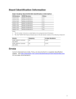
BAP6710H.86A.0075 Notes 1,2 1,2 1,2 1,2 1,2 1,2 1,2 Notes: 1. The AA number is found on a small label on the component side of the board. 2. The Intel® 82P67 PCH Express Chipset used on this AA revision consists of the following component: Device 82P67 Platform Controller Hub (PCH) 82P67 Platform - Intel BOXDP67DEB3 | Product Specification - Page 4
Intel Desktop Board DP67DE Technical Product Specification iv - Intel BOXDP67DEB3 | Product Specification - Page 5
audiences. What This Document Contains Chapter 1 2 3 4 5 Description A description of the hardware used on Intel Desktop Board DP67DE A map of the resources of the Intel Desktop Board The features supported by the BIOS Setup program A description of the BIOS error messages, beep codes, and POST - Intel BOXDP67DEB3 | Product Specification - Page 6
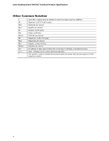
Intel Desktop Board DP67DE Technical Product Specification Other Common Notation # GB GB/s Gb/s KB Kbit kbits/s MB MB/s Mbit Mbits/s xxh x.x V * Used after a signal name to identify an active-low signal (such as USBP0#) Gigabyte (1,073,741,824 bytes) Gigabytes per second Gigabits - Intel BOXDP67DEB3 | Product Specification - Page 7
1.1.2 Board Layout 13 1.1.3 Block Diagram 15 1.2 Legacy Considerations 16 1.3 Online Support 16 1.4 Processor 17 1.4.1 PCI Express x16 Graphics 17 1.5 System Memory 18 1.5.1 Memory Configurations 19 1.6 Intel® P67 Express Chipset 21 1.6.1 USB 21 1.7 SATA Interfaces 22 1.8 Real-Time Clock - Intel BOXDP67DEB3 | Product Specification - Page 8
Intel Desktop Board DP67DE Technical Product Specification 2 Technical Reference 2.1 Memory Resources 37 2.1.1 Addressable 60 3.4 System Management BIOS (SMBIOS 61 3.5 Legacy USB Support 61 3.6 BIOS Updates 62 3.6.1 Language Support 62 3.6.2 Custom Splash Screen 63 3.7 BIOS Recovery 63 3.8 - Intel BOXDP67DEB3 | Product Specification - Page 9
11 2. Components Shown in Figure 1 14 3. Supported Memory Configurations 18 4. Audio Jack Support 24 5. LAN Connector LED States 27 6. Effects in Figure 10 42 11. IEEE 1394a Header 43 12. Front Panel Audio Header for Intel HD Audio 43 13. Front Panel Audio Header for AC '97 Audio 43 14. - Intel BOXDP67DEB3 | Product Specification - Page 10
Intel Desktop Board DP67DE Technical Product Specification 18. Processor, Front, and Rear Chassis (4-Pin) Fan Headers 44 19. Back Panel CIR Emitter (Output) Header 44 20. - Intel BOXDP67DEB3 | Product Specification - Page 11
up to 32 GB of system memory with four DIMMs using 4 Gb memory technology • Support for non-ECC memory • Support for 1.35 V low voltage JEDEC memory Intel® P67 Express Chipset consisting of the Intel® P67 Express Platform Controller Hub (PCH) Graphics Audio Peripheral Interfaces Discrete graphics - Intel BOXDP67DEB3 | Product Specification - Page 12
card connectors • One Conventional PCI bus connector • Intel® BIOS resident in the SPI Flash device • Support for Advanced Configuration and Power Interface (ACPI), Plug and Play, and SMBIOS • Support for PCI* Local Bus Specification Revision 2.2 • Support for PCI Express* Revision 2.0 • Suspend to - Intel BOXDP67DEB3 | Product Specification - Page 13
Product Description 1.1.2 Board Layout Figure 1 shows the location of the major components on Intel Desktop Board DP67DE. Figure 1. Major Board Components 13 - Intel BOXDP67DEB3 | Product Specification - Page 14
(LPC) Debug header Consumer IR emitter (output) header Consumer IR receiver (input) header Main power connector (2 x 12) Battery Piezoelectric speaker Intel P67 Express Chipset SATA connectors Front panel header Alternate front panel power LED header BIOS Setup configuration jumper block Front panel - Intel BOXDP67DEB3 | Product Specification - Page 15
Product Description 1.1.3 Block Diagram Figure 2 is a block diagram of the major functional areas of the board. Figure 2. Block Diagram 15 - Intel BOXDP67DEB3 | Product Specification - Page 16
Board DP67DE Visit this World Wide Web site: http://www.intel.com/products/motherboard/index.htm http://www.intel.com/p/en_US/support?iid=hdr+support http://ark.intel.com Supported processors Chipset information BIOS and driver updates Tested memory Integration information http://processormatch - Intel BOXDP67DEB3 | Product Specification - Page 17
i7, Intel Core i5, and Intel Core i3 processors in an LGA1155 socket support discrete add in graphics cards via the PCI Express 2.0 x16 graphics connector: • Supports PCI Express GEN2 frequency of 2.5 GHz resulting in 5.0 Gb/s each direction (500 MB/s) per lane. The maximum theoretical bandwidth - Intel BOXDP67DEB3 | Product Specification - Page 18
8192 MB DS 4 Gbit 512 M x8/512 M x8 16 Note: "DS" refers to double-sided memory modules (containing two rows of SDRAM) and "SS" refers to single-sided memory modules (containing one row of SDRAM). For information about... Tested Memory Refer to: http://support.intel.com/support/motherboards - Intel BOXDP67DEB3 | Product Specification - Page 19
Product Description 1.5.1 Memory Configurations The Intel Core i7, Intel Core i5, and Intel Core i3 processors in the LGA1155 socket support the following types of memory organization: • Dual channel (Interleaved) mode. This mode offers the highest throughput for real world applications. Dual - Intel BOXDP67DEB3 | Product Specification - Page 20
Technical Product Specification Figure 3 illustrates the memory channel and DIMM configuration. Figure 3. Memory Channel and DIMM Configuration NOTE The Intel Core i7, Intel Core i5, and Intel Core i3 processors require memory to be populated in the DIMM 1 (Channel A, DIMM 1) socket. For best memory - Intel BOXDP67DEB3 | Product Specification - Page 21
Chipset is a centralized controller for the board's I/O paths. For information about The Intel P67 chipset Resources used by the chipset Refer to http://www.intel.com/products/desktop/chipsets/index.htm Chapter 2 1.6.1 USB The board supports up to 14 USB 2.0 ports and two USB 3.0 ports. The - Intel BOXDP67DEB3 | Product Specification - Page 22
Intel Desktop Board DP67DE Technical Product Specification 1.7 SATA Interfaces The board provides six SATA connectors through the PCH, which support one device per connector: • Two internal SATA 6.0 Gb/s connectors (blue) • Two internal SATA 3.0 Gb/s connectors (black) • One internal eSATA 3.0 Gb/s - Intel BOXDP67DEB3 | Product Specification - Page 23
Product Description 1.7.1.1 SATA RAID The board supports Intel Rapid Storage Technology which provides the following RAID (Redundant Array of Independent Drives) levels via the Intel P67 Express Chipset: • RAID 0 - data striping • RAID 1 - data mirroring • RAID 0+1 (or RAID 10) - data striping and - Intel BOXDP67DEB3 | Product Specification - Page 24
electronic hardware. Customers are required to buy or create their own interface modules to connect to Intel Desktop Boards for this feature to work. 1.10 Audio Subsystem The board supports Intel HD Audio via the HDMI interface, DisplayPort interface, and Realtek ALC892 audio codec. The audio - Intel BOXDP67DEB3 | Product Specification - Page 25
to Section 1.3, page 16 1.10.2 Audio Subsystem Components The audio subsystem includes the following components: • Intel H67 Express Chipset • Realtek ALC892 audio codec • Front panel audio header that supports Intel HD audio and AC '97 audio (a 2 x 5-pin header that provides mic in and line out - Intel BOXDP67DEB3 | Product Specification - Page 26
Mbits/s) • Intel P67 Express Chipset • RJ-45 LAN connector with integrated status LEDs Additional features of the LAN subsystem include: • CSMA/CD protocol engine • LAN connect interface between the PCH and the LAN controller • PCI Conventional bus power management ⎯ ACPI technology support ⎯ LAN - Intel BOXDP67DEB3 | Product Specification - Page 27
World Wide Web site. For information about Obtaining LAN software and drivers Refer to http://downloadcenter.intel.com 1.11.3 RJ-45 LAN Connector with Integrated LEDs Two LEDs are built into the RJ-45 LAN connector (shown in Figure 5). Item A B Description Link - Intel BOXDP67DEB3 | Product Specification - Page 28
SMBus interface 1.12.2 Fan Monitoring Fan monitoring can be implemented using Intel® Desktop Utilities or third-party software. For information about The functions page 33 1.12.3 Chassis Intrusion and Detection The board supports a chassis security feature that detects if the chassis cover is - Intel BOXDP67DEB3 | Product Specification - Page 29
chassis fan header Thermal diode, located on the processor die Remote thermal diode Processor fan header Front chassis fan header Thermal diode, located on the Intel P67 PCH Figure 6. Thermal Sensors and Fan Headers 29 - Intel BOXDP67DEB3 | Product Specification - Page 30
Intel Desktop Board DP67DE Technical Product Specification 1.13 Power Management Power management is implemented at several levels, including: • Software support through Advanced Configuration and Power Interface (ACPI) • Hardware support: ⎯ Power connector ⎯ Fan headers ⎯ LAN wake capabilities ⎯ - Intel BOXDP67DEB3 | Product Specification - Page 31
whole into a low-power state. Table 7 lists the power states supported by the board along with the associated system power targets. See the except when provided by battery or external source. No power to the system. Service can be performed safely. Notes: 1. Total system power is dependent on the - Intel BOXDP67DEB3 | Product Specification - Page 32
Intel Desktop Board DP67DE Technical Product Specification 1.13.1.2 Wake- up the computer... Power switch RTC alarm LAN USB PME# signal WAKE# Consumer IR Notes: 1. S4 implies operating system support only. 2. Wake from S4 and S5 is recommended by Microsoft. ...from this state S3, S4, S5 (Note 1) - Intel BOXDP67DEB3 | Product Specification - Page 33
ACPI state requires an operating system that provides full ACPI support. 1.13.2.1 Power Connector ATX12V-compliant power supplies can tachometer input of the hardware monitoring and fan control ASIC • All fan headers support closed-loop fan control that can adjust the fan speed or switch the fan on - Intel BOXDP67DEB3 | Product Specification - Page 34
Intel Desktop Board DP67DE Technical Product Specification 1.13.2.3 LAN Wake Capabilities asserts a wake-up signal that powers up the computer. Depending on the LAN implementation, the board supports LAN wake capabilities with ACPI in the following ways: • The PCI Express WAKE# signal • The PCI - Intel BOXDP67DEB3 | Product Specification - Page 35
asserted, the computer wakes from an ACPI S3, S4, or S5 state (with Wake on PME enabled in the BIOS). 1.13.2.7 WAKE# Signal Wake-up Support When the WAKE# signal on the PCI Express bus is asserted, the computer wakes from an ACPI S3, S4, or S5 state. 1.13.2.8 Wake from - Intel BOXDP67DEB3 | Product Specification - Page 36
Intel Desktop Board DP67DE Technical Product Specification 1.13.2.10 +5 V Standby Power Indicator LED The +5 V standby power indicator LED shows that power is still present even when - Intel BOXDP67DEB3 | Product Specification - Page 37
• BIOS/SPI Flash device (16 Mbit) • Local APIC (19 MB) • Direct Media Interface (40 MB) • Front side bus interrupts (17 MB) • PCI Express configuration space (256 MB) • PCH base address registers PCI Express ports (up to 256 MB) • Memory-mapped I/O that is dynamically allocated for PCI Conventional - Intel BOXDP67DEB3 | Product Specification - Page 38
Intel Desktop Board DP67DE Technical Product Specification Figure 8. Detailed System Memory Address Map 38 - Intel BOXDP67DEB3 | Product Specification - Page 39
K E0000 - EFFFF 800 K - 896 K C8000 - DFFFF 640 K - 800 K 639 K - 640 K 512 K - 639 K 0 K - 512 K A0000 - C7FFF 9FC00 - 9FFFF 80000 - 9FBFF 00000 - 7FFFF Size 32764 MB 64 KB 64 KB 96 KB 160 KB 1 KB 127 KB 512 KB Description Extended memory Runtime BIOS Reserved Potential available high DOS - Intel BOXDP67DEB3 | Product Specification - Page 40
Intel Desktop Board DP67DE Technical Product Specification 2.2.1 Back Panel Connectors Figure 9 shows the location of the back panel connectors for the board. Item A B C D E F G H I J K L M Description USB 2.0 ports - Intel BOXDP67DEB3 | Product Specification - Page 41
Technical Reference 2.2.2 Component-side Connectors and Headers Figure 10 shows the locations of the component-side connectors and headers. Figure 10. Component-side Connectors and Headers 41 - Intel BOXDP67DEB3 | Product Specification - Page 42
Intel Desktop Board DP67DE Technical Product Specification Table 10 lists the component-side connectors and headers identified in Figure 10. Table 10. Component-side Connectors and - Intel BOXDP67DEB3 | Product Specification - Page 43
no pin) Pin 2 4 6 8 10 Signal Name Data A (negative) Ground Data B (negative) +12 V DC Ground Table 12. Front Panel Audio Header for Intel HD Audio Pin Signal Name Pin Signal Name 1 [Port 1] Left channel 2 Ground 3 [Port 1] Right channel 4 PRESENCE# (Dongle present) 5 [Port 2] Right - Intel BOXDP67DEB3 | Product Specification - Page 44
Intel Desktop Board DP67DE Technical Product Specification Table 15. SATA Connectors Pin Signal Name 1 Ground 2 TXP 3 TXN 4 Ground 5 RXN 6 RXP 7 Ground Table 16. S/PDIF Header Pin - Intel BOXDP67DEB3 | Product Specification - Page 45
connector is bus master capable. • SMBus signals are routed to the PCI Conventional bus connector. This enables PCI Conventional bus add-in boards with SMBus support to access sensor data on the desktop board. The specific SMBus signals are as follows: ⎯ The SMBus clock line is connected to pin A40 - Intel BOXDP67DEB3 | Product Specification - Page 46
the following power supply connectors: • Main power - a 2 x 12 connector. This connector is compatible with 2 x 10 connectors previously used on Intel Desktop boards. The board supports the use of ATX12V power supplies with either 2 x 10 or 2 x 12 main power cables. When using a power supply with - Intel BOXDP67DEB3 | Product Specification - Page 47
Technical Reference 2.2.2.4 Front Panel Header This section describes the functions of the front panel header. Table 23 lists the signal names of the front panel header. Figure 11 is a connection diagram for the front panel header. Table 23. Front Panel Header Pin Signal Name Description Pin - Intel BOXDP67DEB3 | Product Specification - Page 48
Intel Desktop Board DP67DE Technical Product Specification 2.2.2.4.3 Power/Sleep LED Header Pins 2 and 4 can be connected to a one- or two-color LED. Table 24 shows the - Intel BOXDP67DEB3 | Product Specification - Page 49
Technical Reference 2.2.2.6 Front Panel USB 2.0 Headers Figure 12 is a connection diagram for the front panel USB 2.0 headers. NOTE • The +5 V DC power on the USB headers is fused. • Use only a front panel USB connector that conforms to the USB 2.0 specification for high-speed USB devices. Figure - Intel BOXDP67DEB3 | Product Specification - Page 50
Intel Desktop Board DP67DE Technical Product Specification 2.3 Jumper Block CAUTION Do not move the jumper with the power on. Always turn off the power and unplug - Intel BOXDP67DEB3 | Product Specification - Page 51
Technical Reference Table 28. BIOS Setup Configuration Jumper Settings Function/Mode Normal Jumper Setting 1-2 Configuration The BIOS uses current configuration information and passwords for booting. Configure 2-3 Recovery None After the POST runs, Setup runs automatically. The maintenance - Intel BOXDP67DEB3 | Product Specification - Page 52
Intel Desktop Board DP67DE Technical Product Specification 2.4 Mechanical Considerations 2.4.1 Form Factor The board is designed to fit into an ATX-form-factor chassis. Figure 14 illustrates - Intel BOXDP67DEB3 | Product Specification - Page 53
amount of standby current required depends on the wake devices supported and manufacturing options. Additional power required will depend on VSB 1.5 A For information about Selecting an appropriate power supply Refer to http://support.intel.com/support/motherboards/desktop/sb /CS-026472.htm 53 - Intel BOXDP67DEB3 | Product Specification - Page 54
/53211.htm All responsibility for determining the adequacy of any thermal or system design remains solely with the reader. Intel makes no warranties or representations that merely following the instructions presented in this document will result in a system with adequate thermal performance. 54 - Intel BOXDP67DEB3 | Product Specification - Page 55
to 120 oC in an open chassis. Figure 15 shows the locations of the localized high temperature zones. Item A B C Description Processor voltage regulator area Processor Intel P67 Express Chipset Figure 15. Localized High Temperature Zones 55 - Intel BOXDP67DEB3 | Product Specification - Page 56
for Components Component Maximum Case Temperature Processor For processor case temperature, see processor datasheets and processor specification updates Intel P67 Express Chipset 111 oC To ensure functionality and reliability, the component is specified for proper operation when Case - Intel BOXDP67DEB3 | Product Specification - Page 57
Technical Reference 2.7 Reliability The Mean Time Between Failures (MTBF) prediction is calculated using component and subassembly random failure rates. The calculation is based on the Telcordia SR-332, Method I Case 1 50% electrical stress, 40 ºC ambient. The MTBF prediction is used to estimate - Intel BOXDP67DEB3 | Product Specification - Page 58
Intel Desktop Board DP67DE Technical Product Specification 58 - Intel BOXDP67DEB3 | Product Specification - Page 59
The board uses an Intel BIOS that is stored in the Serial Peripheral Interface Flash Memory (SPI Flash) and can be updated using a disk-based program. The SPI Flash contains the BIOS Setup program, POST, the PCI auto-configuration utility, LAN EEPROM information, and Plug and Play support. The BIOS - Intel BOXDP67DEB3 | Product Specification - Page 60
Intel Desktop Board DP67DE Technical Product Specification Table 34 lists the BIOS Setup program menu features. Table 34. BIOS Setup Program Menu Bar Maintenance Main Configura- - Intel BOXDP67DEB3 | Product Specification - Page 61
supports an SMBIOS table interface for such operating systems. Using this support, an SMBIOS service Support Legacy USB support enables USB devices to be used even when the operating system's USB drivers are not yet available. Legacy USB support this period if Legacy USB support was set to Disabled in - Intel BOXDP67DEB3 | Product Specification - Page 62
to prevent accidentally installing an incompatible BIOS. NOTE Review the instructions distributed with the upgrade utility before attempting a BIOS update. For information about BIOS update utilities Refer to http://support.intel.com/support/motherboards/desktop/sb /CS-022312.htm. 3.6.1 Language - Intel BOXDP67DEB3 | Product Specification - Page 63
-ROM drive connected to the SATA interface Yes USB removable drive (a USB Flash Drive, for example) Yes USB diskette drive (with a 1.44 MB diskette) No USB hard disk drive No For information about BIOS recovery Refer to http://www.intel.com/support/motherboards/desktop/sb/ cs-023360.htm 63 - Intel BOXDP67DEB3 | Product Specification - Page 64
Intel Desktop Board DP67DE Technical Product Specification 3.8 Boot Options In the BIOS removable drive third, and the network fourth. 3.8.1 Optical Drive Boot Booting from the optical drive is supported in compliance to the El Torito bootable CD-ROM format specification. Under the Boot menu in the - Intel BOXDP67DEB3 | Product Specification - Page 65
of option ROM boot time. NOTE It is possible to optimize the boot process to the point where the system boots so quickly that the Intel logo screen (or a custom logo splash screen) will not be seen. Monitors and hard disk drives with minimum initialization times can also contribute to a boot - Intel BOXDP67DEB3 | Product Specification - Page 66
Intel Desktop Board DP67DE Technical Product Specification 3.10 BIOS Security Features The BIOS includes security features that restrict access to the BIOS Setup program and who - Intel BOXDP67DEB3 | Product Specification - Page 67
BIOS Features 3.11 BIOS Performance Features The BIOS includes the following options to provide custom performance enhancements when using Intel Core i7, Intel Core i5, and Intel Core i3 processors in an LGA1155 socket. • Processor Maximum Non-Turbo Ratio (processor multiplier can only be adjusted - Intel BOXDP67DEB3 | Product Specification - Page 68
Intel Desktop Board DP67DE Technical Product Specification 68 - Intel BOXDP67DEB3 | Product Specification - Page 69
1, page 13 4.2 BIOS Beep Codes Whenever a recoverable error occurs during POST, the BIOS causes the board's speaker to beep an error message describing the problem (see Table 39). Table 39. BIOS Beep Codes Type Pattern F2 Setup/F10 Boot Menu One 0.5 second beep when BIOS is ready to Prompt - Intel BOXDP67DEB3 | Product Specification - Page 70
Intel Desktop Board DP67DE Technical Product Specification 4.3 Front-panel Power LED Blink Codes Whenever a recoverable error occurs during POST, the BIOS causes the board's front panel power LED to blink an error message describing the problem (see Table 40). Table 40. Front-panel Power LED - Intel BOXDP67DEB3 | Product Specification - Page 71
Error Messages and Beep Codes 4.5 Port 80h POST Codes During the POST, the BIOS generates diagnostic progress codes (POST codes) to I/O port 80h. If the POST fails, execution stops and the last POST code generated is left at port 80h. This code is useful for determining the point where an error - Intel BOXDP67DEB3 | Product Specification - Page 72
Intel Desktop Board DP67DE Technical Product Specification Table 43. Port 80h POST Codes Port 80 Code Progress Code Enumeration ACPI S States 0x00,0x01,0x02,0x03,0x04, - Intel BOXDP67DEB3 | Product Specification - Page 73
CPU Initialization CPU PEI Phase 0x41 Begin CPU PEI Init 0x42 XMM instruction enabling 0x43 End CPU PEI Init CPU PEI SMM Phase 0x44 Begin microcode if needed 0x4A Initialize strings to HII database 0x4B Initialize MP support 0x4C CPU DXE Phase End CPU DXE SMM Phase 0x4D CPU DXE - Intel BOXDP67DEB3 | Product Specification - Page 74
Intel Desktop 0x98 0x99 0x9A 0x9B 0xB0 0xB1 BDS BDS driver entry point initialize BDS service routine entry point (can be called multiple times) BDS Step2 BDS of the keyboard Enabling the keyboard Clearing keyboard input buffer Instructing keyboard controller to run Self Test (PS/2 only) Mouse - Intel BOXDP67DEB3 | Product Specification - Page 75
0xE7 Waiting for user input 0xE8 Checking password 0xE9 Entering BIOS setup 0xEB Calling Legacy Option ROMs Runtime Phase/EFI OS Boot 0xF8 EFI boot service ExitBootServices ( ) has been called 0xF9 EFI runtime - Intel BOXDP67DEB3 | Product Specification - Page 76
Intel Desktop Board DP67DE Technical Product Specification Table 44. Typical Port 80h POST Sequence POST Code Description 21 Initializing a chipset component 22 Reading SPD from memory - Intel BOXDP67DEB3 | Product Specification - Page 77
Union Declaration of Conformity statement • Product Ecology statements • Electromagnetic Compatibility (EMC) standards • Product certification markings 5.1.1 Safety Standards Intel Desktop Board DP67DE complies with the safety standards stated in Table 45 when correctly installed in a compatible - Intel BOXDP67DEB3 | Product Specification - Page 78
Desktop Board DP67DE Technical Product Specification 5.1.2 European Union Declaration of Conformity Statement We, Intel Corporation, declare under our sole responsibility that the product Intel® Desktop Board DP67DE is in conformity with all applicable essential requirements necessary for CE marking - Intel BOXDP67DEB3 | Product Specification - Page 79
of this program, including the scope of covered products, available locations, shipping instructions, terms and conditions, etc Intel Product Recycling Program http://www.intel.com/intel/other/ehs/product_ecology Deutsch Als Teil von Intels Engagement für den Umweltschutz hat das Unternehmen das - Intel BOXDP67DEB3 | Product Specification - Page 80
pour en savoir plus sur ce programme, à savoir les produits concernés, les adresses disponibles, les instructions d'expédition, les conditions générales, etc http://www.intel.com/in tel/other/ehs/product_ecology Malay Sebagai sebahagian daripada komitmennya terhadap tanggungjawab persekitaran - Intel BOXDP67DEB3 | Product Specification - Page 81
, nakliye talimatları, kayıtlar ve şartlar v.s dahil bütün ayrıntılarını ögrenmek için lütfen http://www.intel.com/intel/other/ehs/product_ecology Web sayfasına gidin. 5.1.4 EMC Regulations Intel Desktop Board DP67DE complies with the EMC regulations stated in Table 46 when correctly installed in - Intel BOXDP67DEB3 | Product Specification - Page 82
and, if not installed and used in accordance with the instructions, may cause harmful interference to radio communications. However, there help. Any changes or modifications to the equipment not expressly approved by Intel Corporation could void the user's authority to operate the equipment. Tested - Intel BOXDP67DEB3 | Product Specification - Page 83
or television receiver in a domestic environment, it may cause radio interference. Install and use the equipment according to the instruction manual. Korea Class B Statement Korea Class B Statement translation: This equipment is for home use, and has acquired electromagnetic conformity registration - Intel BOXDP67DEB3 | Product Specification - Page 84
Electronic Product Environmental Assessment Tool (EPEAT) Korea e-Standby Program European Union Energy-related Products Directive 2009 (ErP) Refer to http://www.intel.com/go/energystar http://www.epeat.net/ http://www.kemco.or.kr/new_eng/pg02/ pg02100300.asp http://ec.europa.eu/enterprise/policies - Intel BOXDP67DEB3 | Product Specification - Page 85
along with a flammability rating (solder side). China RoHS/Environmentally Friendly Use Period Logo: This is an example of the symbol used on Intel Desktop Boards and associated collateral. The color of the mark may vary depending upon the application. The Environmental Friendly Usage Period (EFUP - Intel BOXDP67DEB3 | Product Specification - Page 86
Intel Desktop Board DP67DE Technical Product Specification 5.2 Battery Disposal Information CAUTION Risk of explosion if the battery is replaced with an incorrect type. Batteries should be - Intel BOXDP67DEB3 | Product Specification - Page 87
Regulatory Compliance and Battery Disposal Information PRECAUCIÓN Existe peligro de explosión si la pila no se cambia de forma adecuada. Utilice solamente pilas iguales o del mismo tipo que las recomendadas por el fabricante del equipo. Para deshacerse de las pilas usadas, siga igualmente las - Intel BOXDP67DEB3 | Product Specification - Page 88
Intel Desktop Board DP67DE Technical Product Specification AWAS Risiko letupan wujud jika bateri digantikan dengan jenis yang tidak betul. Bateri sepatutnya dikitar semula jika boleh. Pelupusan - Intel BOXDP67DEB3 | Product Specification - Page 89
Regulatory Compliance and Battery Disposal Information 89 - Intel BOXDP67DEB3 | Product Specification - Page 90
Intel Desktop Board DP67DE Technical Product Specification 90
-
 1
1 -
 2
2 -
 3
3 -
 4
4 -
 5
5 -
 6
6 -
 7
7 -
8
-
9
-
10
-
11
-
12
-
13
-
14
-
15
-
16
-
17
-
18
-
19
-
20
-
21
-
22
-
23
-
24
-
25
-
26
-
27
-
28
-
29
-
30
-
31
-
32
-
33
-
34
-
35
-
36
-
37
-
38
-
39
-
40
-
41
-
42
-
43
-
44
-
45
-
46
-
47
-
48
-
49
-
50
-
51
-
52
-
53
-
54
-
55
-
56
-
57
-
58
-
59
-
60
-
61
-
62
-
63
-
64
-
65
-
66
-
67
-
68
-
69
-
70
-
71
-
72
-
73
-
74
-
75
-
76
-
77
-
78
-
79
-
80
-
81
-
82
-
83
-
84
-
85
-
86
-
87
-
88
-
89
-
90
 |
 |

Intel® Desktop Board
DP67DE
Technical Product Specification
April 2012
Order Number:
G14698-003
The Intel Desktop Board DP67DE may contain design defects or errors known as errata that may cause the product to deviate from published specifications.
Current characterized errata are documented in the Intel Desktop Board DP67DE Specification Update.