Intel BOXDQ35MP Product Guide
Intel BOXDQ35MP Manual
 |
View all Intel BOXDQ35MP manuals
Add to My Manuals
Save this manual to your list of manuals |
Intel BOXDQ35MP manual content summary:
- Intel BOXDQ35MP | Product Guide - Page 1
Intel® Desktop Board DQ35MP Product Guide Order Number: D90042-004 - Intel BOXDQ35MP | Product Guide - Page 2
Revision History First release of the Intel® Desktop Board DQ35MP Product Guide Second release of the Intel® Desktop Board DQ35MP Product Guide Third release of the Intel® Desktop Board DQ35MP Product Guide Fourth release of the Intel® Desktop Board DQ35MP Product Guide Date May 2007 January 2008 - Intel BOXDQ35MP | Product Guide - Page 3
by Intel. Document Organization The chapters in this Product Guide are arranged as follows: 1 Desktop Board Features: a summary of product features 2 Installing and Replacing Desktop Board Components: instructions on how to install the Desktop Board and other hardware components 3 Updating the BIOS - Intel BOXDQ35MP | Product Guide - Page 4
Intel Desktop Board DQ35MP Product Guide NOTE Notes call attention to important information. Terminology The table below gives descriptions of some common terms used in the product guide. Term Description GB Gigabyte (1,073,741,824 bytes) GHz Gigahertz (one billion hertz) KB Kilobyte ( - Intel BOXDQ35MP | Product Guide - Page 5
1 Desktop Board Features Supported Operating Systems 11 Desktop Board Components 12 Processor ...14 Main Memory...14 Intel® Q35 Express Chipset 15 Intel Q35 Graphics Subsystem 16 Intel® GMA 3100 Graphics Controller 16 Audio Subsystem 17 Legacy Input/Output (I/O) Controller 18 LAN Subsystem - Intel BOXDQ35MP | Product Guide - Page 6
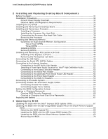
Intel Desktop Board DQ35MP Product Guide 2 Installing and Replacing Desktop Board Components Before You Begin 31 Installation Precautions 32 Prevent Power Supply Overload 32 Observe Safety and Regulatory Requirements 32 Installing the I/O Shield 33 Installing and Removing the Desktop Board 34 - Intel BOXDQ35MP | Product Guide - Page 7
12 2. LAN Connector LEDs 19 3. Intel AMT Status Indicator 20 4. Standby Power Indicator 28 5. Installing the I/O Shield 33 6. Desktop Board DQ35MP Mounting Screw Hole Locations 34 7. Lift the Socket Lever 35 8. Lift the Load Plate 36 9. Remove the Protective Socket Cover 36 10. Remove the - Intel BOXDQ35MP | Product Guide - Page 8
Headers 56 26. Connecting Power Supply Cables 57 27. Location of the BIOS Configuration Jumper Block 58 28. Removing the Battery 66 Tables 1. Feature Summary 9 2. Desktop Board DQ35MP Components 13 3. LAN Connector LEDs 19 4. Intel AMT Status Indicator 20 5. HD Audio Link Header Signal Names - Intel BOXDQ35MP | Product Guide - Page 9
the features of Intel® Desktop Board DQ35MP. Table 1 summarizes the major features of the Desktop Board. Table 1. Feature Summary Form Factor Processor Main Memory Chipset Graphics microATX (243.84 millimeters [9.60 inches] x 243.84 millimeters [9.60 inches]) Support for an Intel® processor - Intel BOXDQ35MP | Product Guide - Page 10
provides IT organizations tamperresistant and persistent management capabilities Related Links: For more information about Desktop Board DQ35MP, including the Technical Product Specification (TPS), BIOS updates, and device drivers, go to: http://support.intel.com/support/motherboards/desktop/ 10 - Intel BOXDQ35MP | Product Guide - Page 11
Desktop Board Features Supported Operating Systems The Desktop Board supports the following operating systems: • Microsoft Windows Vista* Ultimate • Microsoft Windows Vista Enterprise • Microsoft Windows Vista Business • Microsoft Windows Vista Home Premium • Microsoft Windows Vista Home Basic • - Intel BOXDQ35MP | Product Guide - Page 12
Intel Desktop Board DQ35MP Product Guide Desktop Board Components Figure 1 shows the approximate location of the major components on Desktop Board DQ35MP. Figure 1. Desktop Board DQ35MP Components 12 - Intel BOXDQ35MP | Product Guide - Page 13
Desktop Board Features Table 2. Desktop Board DQ35MP Components Label A B C D E F G H I J K L M N O P Q R S T U V W X Y Z AA BB Description Front panel audio header Speaker PCI bus connector PCI Express x1 connector 2 Battery PCI Express x1 connector 1 PCI LED header Chassis intrusion header BIOS - Intel BOXDQ35MP | Product Guide - Page 14
more information about: • Instructions on installing or upgrading the processor, page 35 in Chapter 2 • Supported processors for Desktop Board DQ35MP, http://www.intel.com/go/findCPU Main Memory NOTE To be fully compliant with all applicable Intel ® SDRAM memory specifications, the board should be - Intel BOXDQ35MP | Product Guide - Page 15
Desktop Board Features The Desktop Board supports the dual or single channel memory configurations defined below. • Four 240-pin Double Data Rate 2 (DDR2) SDRAM Dual Inline Memory Module (DIMM) connectors with gold-plated contacts, 1.8 V only • Support for: ⎯ Unbuffered, non-registered single or - Intel BOXDQ35MP | Product Guide - Page 16
Intel Desktop Board DQ35MP Product Guide Intel Q35 Graphics Subsystem The Intel Q35 Express Chipset contains two separate, mutually exclusive graphics options. Either the integrated Intel® Graphics Media Accelerator 3100 (Intel® GMA 3100) graphics controller is used or a PCI Express x16 add-in card - Intel BOXDQ35MP | Product Guide - Page 17
back panel connectors and the Intel High Definition Audio front panel header Related Links: Go to the following link or pages for more information about: • Audio drivers and utilities http://support.intel.com/support/motherboards/desktop/ • Installing the front panel audio solution, page 52 • The - Intel BOXDQ35MP | Product Guide - Page 18
status LEDs The subsystem also features: • CSMA/CD protocol engine • LAN connect interface between ICH9DO and the LAN controller • PCI bus power management Related Links: Go to the following link for information about LAN software and drivers: http://support.intel.com/support/motherboards/desktop 18 - Intel BOXDQ35MP | Product Guide - Page 19
Desktop Board Features RJ-45 LAN Connector LEDs Two LEDs are built into the RJ-45 LAN connector located on the back panel (see Figure 2). These LEDs indicate the status of the LAN. Figure 2. LAN Connector LEDs Table 3 describes the LED states when the board is powered up and the LAN subsystem is - Intel BOXDQ35MP | Product Guide - Page 20
Intel Desktop Board DQ35MP Product Guide The Intel AMT subsystem consists of: • ARC4 microcontroller embedded in the Intel Q35 Graphics and Memory Controller Hub (GMCH) • ICH9DO (Intel® Management Engine function) • Intel 82566DM Gigabit (10/100/1000 Mb/s) Ethernet LAN controller • Channel A DIMM - Intel BOXDQ35MP | Product Guide - Page 21
Desktop Board Features Hi-Speed USB 2.0 Support The Desktop Board supports up to 12 USB 2.0 ports (six ports routed USB 1.1 speeds. USB 2.0 support requires both an operating system and drivers that fully support USB 2.0 transfer rates. Disabling Hi-Speed USB in the BIOS reverts all USB 2.0 ports to - Intel BOXDQ35MP | Product Guide - Page 22
on configuring your system for Intel Rapid Recover Technology see Chapter 5. Expandability For system expansion, the Desktop Board provides the following expansion slots: • Two PCI Express x1 connectors • One PCI Express x16 connector • One PCI bus connector BIOS The BIOS provides the Power-On Self - Intel BOXDQ35MP | Product Guide - Page 23
Desktop Board Features Security Passwords The BIOS includes security features that restrict whether the BIOS Setup program can be accessed and who can boot the computer. A supervisor password and a user password can be set for the BIOS Setup and for booting the computer, with the following - Intel BOXDQ35MP | Product Guide - Page 24
Intel Desktop Board DQ35MP Product Guide Hard Disk Drive Password Feature During BIOS POST During every BIOS POST execution, if a User hard disk drive password is present on the hard drive, POST execution will pause to prompt the user to enter the - Intel BOXDQ35MP | Product Guide - Page 25
fans off as needed Chassis Intrusion The board supports a chassis security feature that detects if the chassis cover has been removed. The security feature uses a mechanical switch on the chassis that can be connected to the chassis intrusion header on the Desktop Board. See Figure 23 on page 51 for - Intel BOXDQ35MP | Product Guide - Page 26
Intel Desktop Board DQ35MP Product Guide ACPI ACPI gives the operating system direct control over the power management and Plug and Play functions of a computer. The use of ACPI with the Desktop Board requires an operating system that provides full ACPI support. Hardware Support Power Connectors - Intel BOXDQ35MP | Product Guide - Page 27
ways: • The PCI Express WAKE# signal • The PCI bus PME# signal for PCI 2.3 compliant LAN designs • By Ping • Magic Packet • The onboard LAN subsystem Desktop Board DQ35MP supports waking the Intel Management Engine over the network. This can be enabled in the BIOS and allows Intel AMT to be remotely - Intel BOXDQ35MP | Product Guide - Page 28
Intel Desktop Board DQ35MP Product Guide The Desktop Board supports the PCI Bus Power Management Interface Specification. Add-in cards that support this specification can participate in power management and can be used to wake the computer. +5 V Standby Power Indicator CAUTION If the AC power has - Intel BOXDQ35MP | Product Guide - Page 29
Desktop Board Features PME# Signal Wake-up Support When the PME# signal on the PCI bus is asserted, the computer wakes from an ACPI S1, S3, S4, or S5 state. WAKE# Signal Wake-up Support When the WAKE# signal on the PCI Express bus is asserted, the computer wakes from an ACPI S1, S3, S4, or S5 state - Intel BOXDQ35MP | Product Guide - Page 30
Intel Desktop Board DQ35MP Product Guide 30 - Intel BOXDQ35MP | Product Guide - Page 31
Desktop Board • Install and remove a processor • Install and remove memory • Install and remove a PCI Express x16 card • Connect the IDE and Serial ATA cables • Connect to the internal headers • Connect to the audio system • Connect chassis fan and power supply cables • Set the BIOS configuration - Intel BOXDQ35MP | Product Guide - Page 32
Intel Desktop Board DQ35MP Product Guide Installation Precautions When you install and test the Intel Desktop Board, observe all warnings and cautions in the installation instructions all warnings and cautions that instruct you to refer computer servicing to qualified technical personnel. Prevent - Intel BOXDQ35MP | Product Guide - Page 33
transmissions, protects internal components from dust and foreign objects, and promotes correct airflow within the chassis. Install the I/O shield before installing the Desktop Board in the chassis. Place the shield inside the chassis as shown in Figure 5. Press the shield into place so that it fits - Intel BOXDQ35MP | Product Guide - Page 34
Intel Desktop Board DQ35MP Product Guide Installing and Removing the Desktop Board CAUTION Only qualified technical manual for instructions on installing and removing the Desktop Board. Figure 6 shows the location of the mounting screw holes for Desktop Board DQ35MP. Figure 6. Desktop Board DQ35MP - Intel BOXDQ35MP | Product Guide - Page 35
Installing and Replacing Desktop Board Components Installing and Removing a Processor Instructions on how to install the processor to the Desktop Board are given below. Installing a Processor CAUTION Before installing or removing the processor, make sure the AC power has been removed by unplugging - Intel BOXDQ35MP | Product Guide - Page 36
Intel Desktop Board DQ35MP Product Guide 3. Lift the load plate (Figure 8, A). Do not touch the socket contacts (Figure 8, B). Figure 8. Lift the Load Plate 4. Remove the plastic protective socket cover from the - Intel BOXDQ35MP | Product Guide - Page 37
Desktop Board Components 5. Remove the processor from the protective processor cover. Hold the processor only at the edges, being careful not to touch the bottom of the processor (see Figure 10 the processor is removed from the socket. Figure 10. Remove the Processor from the Protective Processor - Intel BOXDQ35MP | Product Guide - Page 38
Intel Desktop Board DQ35MP Product Guide 7. Pressing down on the load plate (Figure 12, A), close and engage the socket lever (Figure 12, B). Figure 12. Close the Load Plate Installing the Processor Fan Heat Sink Desktop Board DQ35MP has mounting holes for a processor fan heat sink. For instructions - Intel BOXDQ35MP | Product Guide - Page 39
Installing and Replacing Desktop Board Components Connecting the Processor Fan Heat Sink Cable Connect the processor fan heat sink cable to the 4-pin processor fan header (see Figure 13). A fan with a 4-pin connector as shown in Figure 13, A is - Intel BOXDQ35MP | Product Guide - Page 40
Intel Desktop Board DQ35MP Product Guide Removing the Processor For instructions on how to remove the processor fan heat sink and processor, refer to the processor installation manual. Installing and Removing Memory NOTE To be fully compliant with all applicable Intel SDRAM memory specifications, - Intel BOXDQ35MP | Product Guide - Page 41
Installing and Replacing Desktop Board Components Guidelines for Dual Channel Memory Configuration Before installing DIMMs, read and follow these guidelines for dual channel configuration. Two or Four DIMMs Install a matched pair of DIMMs equal in speed - Intel BOXDQ35MP | Product Guide - Page 42
Intel Desktop Board DQ35MP Product Guide Three DIMMs If you want to use three DIMMs in a dual-channel configuration, install DIMM 0 or DIMM 1 of channel B (see Figure 16). Figure 16. Dual Channel Memory Configuration with Three DIMMs NOTE All other memory configurations will result in single channel - Intel BOXDQ35MP | Product Guide - Page 43
Installing and Replacing Desktop Board Components Installing DIMMs To make sure you have the correct DIMM, place it on the illustration of the DDR2 DIMM in Figure 17. All the notches should match with the DDR2 DIMM. Figure 17. Use DDR2 DIMMs 43 - Intel BOXDQ35MP | Product Guide - Page 44
Intel Desktop Board DQ35MP Product Guide NOTE Memory must be installed in the Channel A, DIMM 0 socket to enable Intel Quiet System Technology. To install a DIMM, follow these steps: 1. Observe the precautions in "Before You Begin" on page 31. 2. Turn off all peripheral devices connected to the - Intel BOXDQ35MP | Product Guide - Page 45
Installing and Replacing Desktop Board Components 7. Insert the bottom edge of the DIMM into the : 1. Observe the precautions in "Before You Begin" on page 31. 2. Turn off all peripheral devices connected to the computer. Turn off the computer. 3. Remove the AC power cord from the computer. 4. Remove - Intel BOXDQ35MP | Product Guide - Page 46
Intel Desktop Board DQ35MP Product Guide Installing and Removing a PCI Express x16 Card CAUTION When installing a PCI Express x16 card on the Desktop Board, ensure that the card is fully seated in the PCI Express x16 connector before you power on the system. If the card is not fully seated in the - Intel BOXDQ35MP | Product Guide - Page 47
Installing and Replacing Desktop Board Components Removing the PCI Express x16 Card Follow these instructions to remove the PCI Express x16 card from the connector: 1. Observe the precautions in "Before You Begin" on page 31. 2. Remove the screw (Figure 20, A) that secures the card's - Intel BOXDQ35MP | Product Guide - Page 48
Intel Desktop Board DQ35MP Product Guide Connecting the IDE Cable The IDE cable can be used to connect two IDE drives to the Desktop Board. The cable supports the ATA-66/100 transfer protocol. Figure 21 shows the correct installation of the cable. NOTES ATA-66/100 compatible cables are backward - Intel BOXDQ35MP | Product Guide - Page 49
Installing and Replacing Desktop Board Components Figure 21. Connecting the IDE Cable 49 - Intel BOXDQ35MP | Product Guide - Page 50
Intel Desktop Board DQ35MP Product Guide Connecting the Serial ATA (SATA) Cables SATA cables support the Serial ATA protocol. Each cable can be used to connect a single internal SATA drive to the Desktop Board. For correct cable function: 1. Observe the precaution in "Before You Begin" on page 31. - Intel BOXDQ35MP | Product Guide - Page 51
Installing and Replacing Desktop Board Components Connecting to the Internal Headers Before connecting cables to the internal headers, observe the precautions in "Before You Begin" on page 31. Figure 23 shows the location of the internal headers. Item Description A HD Audio Link B Front Panel - Intel BOXDQ35MP | Product Guide - Page 52
Intel Desktop Board DQ35MP Product Guide Connecting to the HD Audio Link Header See Figure 23, A for the location of the HD Audio Link header. Table 5 shows the pin assignments for the header. Table 5. HD Audio Link Header Signal Names Pin Signal Name 1 BCLK 3 RST# Pin Signal Name 2 - Intel BOXDQ35MP | Product Guide - Page 53
Desktop Board Components To install the cable that connects the front panel audio solution to the front panel audio header, follow these steps: 1. Observe the precautions in "Before You Begin" on page 31. 2. Turn off all peripheral devices connected # 4 DTR 6 DSR 8 CTS 10 No Connection 53 - Intel BOXDQ35MP | Product Guide - Page 54
Intel Desktop Board DQ35MP Product Guide Connecting to the Alternate Front Panel Power LED Header Figure 23, F on page 51 shows the location of the alternate front panel power LED header. Pins 1 and 3 of this header duplicate the signals on pins 2 and 4 of the front panel header. If your chassis - Intel BOXDQ35MP | Product Guide - Page 55
Installing and Replacing Desktop Board Components Connecting to the USB 2.0 Headers Before connecting to the USB 2.0 headers, USB device. Connecting to the Audio System After installing the RealTek audio driver from the Intel Express Installer DVD-ROM, the multi-channel audio feature can be enabled - Intel BOXDQ35MP | Product Guide - Page 56
Intel Desktop Board DQ35MP Product Guide NOTE The back panel audio line out connector is designed to power either headphones or amplified speakers only. Poor audio quality may occur if passive (non-amplified) speakers are connected to this output. Connecting Chassis Fan and Power Supply Cables - Intel BOXDQ35MP | Product Guide - Page 57
properly. The 2 x 12 pin main power connector on the Desktop Board is backwards compatible with ATX12V power supplies with 2 x 10 connectors. Figure 26 shows the location of the Desktop Board power connectors. Figure 26. Connecting Power Supply Cables 1. Observe the precautions in "Before You Begin - Intel BOXDQ35MP | Product Guide - Page 58
Intel Desktop Board DQ35MP Product Guide Setting the BIOS Configuration Jumper NOTE Always turn off the power and unplug the power cord from the computer before moving the jumper. Moving the jumper with the - Intel BOXDQ35MP | Product Guide - Page 59
and Replacing Desktop Board Components Table 12. Jumper Settings for the BIOS Setup Program Modes Jumper Setting Mode Normal (default) (1-2) Description The BIOS uses the current configuration and passwords for booting. Configure (2-3) After the Power-On Self-Test (POST) runs, the BIOS displays - Intel BOXDQ35MP | Product Guide - Page 60
Intel Desktop Board DQ35MP Product Guide Clearing or Changing Passwords This section describes how to clear or change the following passwords: • BIOS security passwords (user and supervisor) • Hard disk drive passwords (User and Master) Clearing BIOS values and exit Setup. 10. Turn off the computer. - Intel BOXDQ35MP | Product Guide - Page 61
Desktop Board A coin-cell battery (CR2032) powers the real-time clock and CMOS memory. When the computer is not plugged into a wall socket, the battery with 3.3 VSB applied. When the voltage drops below a certain level, the BIOS Setup program settings stored in CMOS RAM (for example, the date and time - Intel BOXDQ35MP | Product Guide - Page 62
Intel Desktop Board DQ35MP Product Guide OBS! Det kan oppstå eksplosjonsfare hvis batteriet skiftes ut med feil type. Brukte batterier bør kastes i henhold til gjeldende miljølovgivning. VIKTIGT! Risk för explosion om batteriet - Intel BOXDQ35MP | Product Guide - Page 63
Installing and Replacing Desktop Board Components AŚCIAROŽZNA UPOZORNÌNÍ V případě výměny baterie za nesprávný druh může dojít k výbuchu. Je-li to možné, baterie by měly být recyklovány. Baterie je třeba - Intel BOXDQ35MP | Product Guide - Page 64
Intel Desktop Board DQ35MP Product Guide UPOZORNENIE Ak batériu vymeníte za nesprávny typ, hrozí nebezpečenstvo jej výbuchu. Batérie by sa mali podľa možnosti vždy recyklovať. - Intel BOXDQ35MP | Product Guide - Page 65
Installing and Replacing Desktop Board Components 65 - Intel BOXDQ35MP | Product Guide - Page 66
Intel Desktop Board DQ35MP Product Guide To replace the battery, follow these steps: 1. Observe the precautions in "Before You Begin" (see page 31). 2. Turn off all peripheral devices connected to the computer. Disconnect the computer's power cord from the AC power source (wall outlet or power - Intel BOXDQ35MP | Product Guide - Page 67
of the Intel® Flash Memory Update Utility and the ease of use of Windows-based installation wizards. To update the BIOS with the Intel Express BIOS Update utility: 1. Go to the Intel World Wide Web site: http://support.intel.com/support/motherboards/desktop/ 2. Navigate to the DQ35MP page, click - Intel BOXDQ35MP | Product Guide - Page 68
• Intel Flash Memory Update Utility You can obtain either of these files through your computer supplier or by navigating to the Desktop Board DQ35MP page on the Intel World Wide Web site at: http://support.intel.com/support/motherboards/desktop Navigate to the DQ35MP page, click "[view] Latest BIOS - Intel BOXDQ35MP | Product Guide - Page 69
USB flash drive or other bootable USB media. The Iflash Memory update utility allows you to: • Update the BIOS and Intel Management Engine in flash memory • Update the language section of the BIOS NOTE Review the instructions distributed with the update utility before attempting a BIOS update. 69 - Intel BOXDQ35MP | Product Guide - Page 70
requirements, a CD-R or USB flash drive with the .BIO file in the root directory will be required. Related Links: For more information about updating the Intel Desktop Board BIOS or recovering from a BIOS update failure, go to: http://support.intel.com/support/motherboards/desktop/sb/CS-022312.htm - Intel BOXDQ35MP | Product Guide - Page 71
Windows XP operating system and SATA hard drives. Configuring the BIOS for Intel Matrix Storage Technology 1. Assemble your system and attach one or more SATA hard drives to the SATA connectors. 2. Enter system BIOS Setup by pressing the key after the Power-On-Self-Test (POST) memory RAID 10 ( - Intel BOXDQ35MP | Product Guide - Page 72
the Windows installation and install all necessary drivers. 4. Install the Intel Matrix Storage Console software via the Intel Express Installer CD/DVD included with your desktop board or after downloading it from the Internet at http://support.intel.com/support/motherboards/desktop/. The Intel - Intel BOXDQ35MP | Product Guide - Page 73
When using the Update On Request Intel Rapid Recover Technology NOTE Intel Rapid Recover Technology does not support RAID 5. Intel Rapid Recover Technology can be Enabled or Disabled in the system BIOS menu. To enable Intel instructions in Chapter 5 to install the Intel Matrix Storage RAID driver - Intel BOXDQ35MP | Product Guide - Page 74
Intel Desktop Board DQ35MP Product Guide Creating a Recovery Volume A recovery volume consists of two disks - a master disk and a recovery disk. A recovery volume can be created with either the RAID Option ROM (OROM) or the Intel® Matrix Storage Console application. Creating a Recovery Volume Using - Intel BOXDQ35MP | Product Guide - Page 75
- either continuous update or manual update. To change from Continuous Update mode to Update On Request mode using the Intel Matrix Storage Console The recovery disk will now be mounted and can be seen in Microsoft Windows Explorer. NOTE Individual files or folders can be copied from the recovery - Intel BOXDQ35MP | Product Guide - Page 76
Intel Desktop Board DQ35MP Product Guide To un-mount the recovery disk, complete the following steps: 1. In the Advanced mode, right-click on the recovery volume name. 2. Select Access Recovery Drive - Intel BOXDQ35MP | Product Guide - Page 77
A Error Messages and Indicators Desktop Board DQ35MP reports POST errors in two ways: • By sounding a beep code • By displaying an error message on the monitor BIOS Beep Codes The BIOS also issues a beep code (one long tone followed by two short tones) during POST if the video configuration fails - Intel BOXDQ35MP | Product Guide - Page 78
Intel Desktop Board DQ35MP Product Guide 78 - Intel BOXDQ35MP | Product Guide - Page 79
Compatibility (EMC) regulations • Product certifications Safety Standards Desktop Board DQ35MP complies with the safety standards stated in Table Place Battery Marking There is insufficient space on this Desktop Board to provide instructions for replacing and disposing of the Lithium ion coin - Intel BOXDQ35MP | Product Guide - Page 80
Intel Desktop Board DQ35MP Product Guide European Union Declaration of Conformity Statement We, Intel Corporation, declare under our sole responsibility that the product Intel® Desktop Board DQ35MP is in conformity with all applicable essential requirements necessary for CE marking, following the - Intel BOXDQ35MP | Product Guide - Page 81
consult http://www.intel.com/intel/other/ehs/product_ecology for the details of this program, including the scope of covered products, available locations, shipping instructions, terms and conditions, etc Intel Product Recycling Program http://www.intel.com/intel/other/ehs/product_ecology 81 - Intel BOXDQ35MP | Product Guide - Page 82
Intel Desktop Board DQ35MP Product Guide Deutsch Als Teil von Intels Engagement für den Umweltschutz hat das Unternehmen das Intel Produkt-Recyclingprogramm implementiert, das Einzelhandelskunden von Intel , les instructions d'expédition, les conditions générales, etc. http://www.intel.com/in - Intel BOXDQ35MP | Product Guide - Page 83
is lead. Intel Desktop Board DQ35MP is lead-free although certain discrete components used on the board contain a small Desktop Board is referred to as "Lead-free second level interconnect." The board substrate and the solder connections from the board to the components (second-level connections - Intel BOXDQ35MP | Product Guide - Page 84
Intel Desktop Board DQ35MP Product Guide Table 16 shows the lead-free board markings as they appear on the board and accompanying collateral. Table 16. Lead-Free Board concentration level in the Intel Desktop Board substrate and the solder connections or from the board to the components ( - Intel BOXDQ35MP | Product Guide - Page 85
Regulatory Compliance EMC Regulations Desktop Board DQ35MP complies with the EMC regulations stated in Table 17 when correctly installed in a compatible host system. in a domestic environment, it may cause radio interference. Install and use the equipment according to the instruction manual. 85 - Intel BOXDQ35MP | Product Guide - Page 86
Intel Desktop Board DQ35MP Product Guide Korean Class B statement translation: This is household equipment and are marked accordingly. Pay close attention to the following when reading the installation instructions for the host chassis, power supply, and other modules: • Product certifications or - Intel BOXDQ35MP | Product Guide - Page 87
for Intel Desktop Boards: E210882. Mark FCC Declaration of Conformity logo mark for Class B equipment. Includes Intel name and DQ35MP model CPU-DQ35MP (B). Taiwan BSMI (Bureau of Standards, Metrology and Inspections) mark. Includes adjacent Intel company number, D33025. Printed wiring board - Intel BOXDQ35MP | Product Guide - Page 88
Intel Desktop Board DQ35MP Product Guide Chassis and Component Certifications Ensure that the chassis Radio and Telecommunications Terminal Equipment (R&TTE) directive may also apply depending on product features. In the United States A certification mark by a Nationally Recognized Testing Laboratory
-
 1
1 -
 2
2 -
 3
3 -
 4
4 -
 5
5 -
 6
6 -
 7
7 -
8
-
9
-
10
-
11
-
12
-
13
-
14
-
15
-
16
-
17
-
18
-
19
-
20
-
21
-
22
-
23
-
24
-
25
-
26
-
27
-
28
-
29
-
30
-
31
-
32
-
33
-
34
-
35
-
36
-
37
-
38
-
39
-
40
-
41
-
42
-
43
-
44
-
45
-
46
-
47
-
48
-
49
-
50
-
51
-
52
-
53
-
54
-
55
-
56
-
57
-
58
-
59
-
60
-
61
-
62
-
63
-
64
-
65
-
66
-
67
-
68
-
69
-
70
-
71
-
72
-
73
-
74
-
75
-
76
-
77
-
78
-
79
-
80
-
81
-
82
-
83
-
84
-
85
-
86
-
87
-
88
 |
 |

Intel
®
Desktop Board DQ35MP
Product Guide
Order Number:
D90042-004