Intel BOXDQ35MPE Product Guide
Intel BOXDQ35MPE Manual
 |
View all Intel BOXDQ35MPE manuals
Add to My Manuals
Save this manual to your list of manuals |
Intel BOXDQ35MPE manual content summary:
- Intel BOXDQ35MPE | Product Guide - Page 1
Intel® Desktop Board DQ35MP Product Guide Order Number: D90042-004 - Intel BOXDQ35MPE | Product Guide - Page 2
Intel® Desktop Board DQ35MP Product Guide Second release of the Intel® Desktop Board DQ35MP Product Guide Third release of the Intel® Desktop Board DQ35MP Product Guide Fourth release of the Intel® Desktop Board DQ35MP Product Guide the instructions, may approved by Intel Corporation could void the - Intel BOXDQ35MPE | Product Guide - Page 3
equipment, etc., may not be supported without further evaluation by Intel. Document Organization The chapters in this Product Guide are arranged as follows: 1 Desktop Board Features: a summary of product features 2 Installing and Replacing Desktop Board Components: instructions on how to install the - Intel BOXDQ35MPE | Product Guide - Page 4
Intel Desktop Board DQ35MP Product Guide NOTE Notes call attention to important information. Terminology The table below gives descriptions of some common terms used in the product guide. Term Description GB Gigabyte (1,073,741,824 bytes) GHz Gigahertz (one billion hertz) KB Kilobyte ( - Intel BOXDQ35MPE | Product Guide - Page 5
Contents 1 Desktop Board Features Supported Operating Systems 11 Desktop Board Components 12 Processor ...14 Main Memory...14 Intel® Q35 Express Chipset 15 Intel Q35 Graphics Subsystem 16 Intel® GMA 3100 Graphics Controller 16 Audio Subsystem 17 Legacy Input/Output (I/O) Controller 18 LAN - Intel BOXDQ35MPE | Product Guide - Page 6
Guide 2 Installing and Replacing Desktop Board Components Before You Begin 31 Installation Precautions 32 Prevent Power Supply Overload 32 Observe Safety and Regulatory Requirements 32 Installing the I/O Shield 33 Installing and Removing the Desktop Board 34 Installing and Removing a Processor - Intel BOXDQ35MPE | Product Guide - Page 7
Storage Technology 71 Creating Your RAID Set 71 Loading the Intel Matrix Storage Technology RAID Drivers and Software 72 Setting Up a "RAID Ready" System 72 5 Configuring for Intel® Rapid Recover Technology Enabling Intel Rapid Recover Technology 73 Creating a Recovery Volume 74 Creating - Intel BOXDQ35MPE | Product Guide - Page 8
Intel Desktop Board DQ35MP Product Guide 19. Installing a PCI Express x16 Card 46 20. Removing a PCI Components 13 3. LAN Connector LEDs 19 4. Intel AMT Status Indicator 20 5. HD Audio Link Header Signal Names 52 6. Front Panel Intel High Definition Audio Header Signal Names 52 7. Chassis - Intel BOXDQ35MPE | Product Guide - Page 9
for an Intel® processor in the LGA775 package • Four 240-pin, DDR2 1.8 V (only) SDRAM Dual Inline Memory Module (DIMM) sockets • 800/667 MHz single or dual channel DDR2 SDRAM interface • Support for up to 8 GB of system memory Intel® Q35 Express Chipset consisting of: • Intel® Q35 Express Chipset - Intel BOXDQ35MPE | Product Guide - Page 10
organizations tamperresistant and persistent management capabilities Related Links: For more information about Desktop Board DQ35MP, including the Technical Product Specification (TPS), BIOS updates, and device drivers, go to: http://support.intel.com/support/motherboards/desktop/ 10 - Intel BOXDQ35MPE | Product Guide - Page 11
Operating Systems The Desktop Board supports the following operating systems: • Microsoft Windows Vista* Ultimate • Microsoft Windows Vista Enterprise • Microsoft Windows Vista Business • Microsoft Windows Vista Home Premium • Microsoft Windows Vista Home - Intel BOXDQ35MPE | Product Guide - Page 12
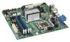
Intel Desktop Board DQ35MP Product Guide Desktop Board Components Figure 1 shows the approximate location of the major components on Desktop Board DQ35MP. Figure 1. Desktop Board DQ35MP Components 12 - Intel BOXDQ35MPE | Product Guide - Page 13
PCI Express x1 connector 1 PCI Express x16 connector Rear chassis fan header (3-pin) Back panel connectors 12 V processor core voltage connector (2 x 2 pin) Processor socket Processor fan header (4-pin) Serial header Main power connector (2 x 12 pin) DDR2 DIMM 0 sockets DDR2 DIMM 1 sockets Front - Intel BOXDQ35MPE | Product Guide - Page 14
. Related Links: Go to the following page or link for more information about: • Instructions on installing or upgrading the processor, page 35 in Chapter 2 • Supported processors for Desktop Board DQ35MP, http://www.intel.com/go/findCPU Main Memory NOTE To be fully compliant with all applicable - Intel BOXDQ35MPE | Product Guide - Page 15
/mbsearch.asp or http://www.intel.com/products/motherboard/index.htm?iid=HMPAGE+Header_2_P roduct_MB • PC Serial Presence Detect Specification, http://www.intel.com/technology/memory/ddr/specs/dda8c16_32x64ag_a.pdf Intel® Q35 Express Chipset The Intel Q35 Express Chipset consists of the following - Intel BOXDQ35MPE | Product Guide - Page 16
Guide Intel Q35 Graphics Subsystem The Intel Q35 Express Chipset contains two separate, mutually exclusive graphics options. Either the integrated Intel® Graphics Media Accelerator 3100 (Intel 30 fps full screen ⎯ Dynamic Video Memory Technology (DVMT) supports up to 287 MB • Display ⎯ Up to 2048 x - Intel BOXDQ35MPE | Product Guide - Page 17
Audio front panel header Related Links: Go to the following link or pages for more information about: • Audio drivers and utilities http://support.intel.com/support/motherboards/desktop/ • Installing the front panel audio solution, page 52 • The location of audio connectors, Figure 24 on page - Intel BOXDQ35MPE | Product Guide - Page 18
connect interface between ICH9DO and the LAN controller • PCI bus power management Related Links: Go to the following link for information about LAN software and drivers: http://support.intel.com/support/motherboards/desktop 18 - Intel BOXDQ35MPE | Product Guide - Page 19
in addition to offering encrypted and persistent asset management and remote diagnostics and/or recovery capabilities for networked platforms. With Intel AMT, IT organizations can easily get accurate platform information, and can perform remote updating, diagnostics, debugging and repair of a system - Intel BOXDQ35MPE | Product Guide - Page 20
Board DQ35MP Product Guide The Intel AMT subsystem consists of: • ARC4 microcontroller embedded in the Intel Q35 Graphics and Memory Controller Hub (GMCH) • ICH9DO (Intel® Management Engine function) • Intel 82566DM Gigabit (10/100/1000 Mb/s) Ethernet LAN controller • Channel A DIMM(s) • BIOS - Intel BOXDQ35MPE | Product Guide - Page 21
1.1 speeds. USB 2.0 support requires both an operating system and drivers that fully support USB 2.0 transfer rates. between the processor and peripheral devices such as hard disk drives and CD-ROM drives. The interface supports: • Up for RAID using Intel® Matrix Storage Technology see Chapter 4. 21 - Intel BOXDQ35MPE | Product Guide - Page 22
Guide Intel® Rapid Recover Technology Intel (SPI) Flash. The BIOS can be updated by following the instructions on page 67 in Chapter 3. Serial ATA and IDE Auto device. You can override the auto-configuration options by specifying manual configuration in the BIOS Setup program. PCI* and PCI - Intel BOXDQ35MPE | Product Guide - Page 23
hard disk drive password security feature can only be used on ATA hard disks that support the ATA Security Mode feature set. It supports Serial ATA hard disk drives in IDE, AHCI, and RAID modes. For instructions on resetting the password, see Clearing or Changing Hard Disk Drive Passwords on page 61 - Intel BOXDQ35MPE | Product Guide - Page 24
Intel Desktop Board DQ35MP Product Guide Hard Disk Drive Password Feature During BIOS POST During every BIOS activating the TPM, refer to the Trusted Platform Module (TPM) Quick Reference Guide. Hardware Management Features The hardware management features of Desktop Board DQ35MP enable the board - Intel BOXDQ35MPE | Product Guide - Page 25
to enable Intel Quiet System Technology. • Fan speed controllers and sensors integrated into the ICH9DO • Thermal sensors in the processor, GMCH, speed or switch the fans off as needed Chassis Intrusion The board supports a chassis security feature that detects if the chassis cover has been removed - Intel BOXDQ35MPE | Product Guide - Page 26
Intel Desktop Board DQ35MP Product Guide ACPI ACPI gives the operating system direct control over the power management and Plug and Play functions of a computer. The use of ACPI with the Desktop Board requires an operating system that provides full ACPI support. Hardware Support headers support - Intel BOXDQ35MPE | Product Guide - Page 27
LAN designs • By Ping • Magic Packet • The onboard LAN subsystem Desktop Board DQ35MP supports waking the Intel Management Engine over the network. This can be enabled in the BIOS and allows Intel AMT to be remotely turned on through a wake packet generated by a management console application - Intel BOXDQ35MPE | Product Guide - Page 28
Intel Desktop Board DQ35MP Product Guide The Desktop Board supports the PCI Bus Power Management Interface Specification. Add-in cards that support : http://support.intel.com/support/motherboards/desktop/ Wake from USB NOTE Wake from USB requires the use of a USB peripheral that supports Wake from - Intel BOXDQ35MPE | Product Guide - Page 29
, S3, S4, or S5 state. WAKE# Signal Wake-up Support When the WAKE# signal on the PCI Express bus is asserted, new ENERGY STAR requirements: http://www.intel.com/go/EnergyStar Speaker A speaker is computer is turned off. Go to page 61 for instructions on how to replace the battery. Real-Time Clock The - Intel BOXDQ35MPE | Product Guide - Page 30
Intel Desktop Board DQ35MP Product Guide 30 - Intel BOXDQ35MPE | Product Guide - Page 31
Replacing Desktop Board Components This chapter tells you how to: • Install the I/O shield • Install and remove the Desktop Board • Install and remove a processor • Install and remove memory • Install and remove a PCI Express x16 card • Connect the IDE and Serial ATA cables • Connect to the internal - Intel BOXDQ35MPE | Product Guide - Page 32
sharp corners on the chassis • Hot components (such as processors, voltage regulators, and heat sinks) • Damage to wires that could cause a short circuit Observe all warnings and cautions that instruct you to refer computer servicing to qualified technical personnel. Prevent Power Supply Overload Do - Intel BOXDQ35MPE | Product Guide - Page 33
Installing and Replacing Desktop Board Components Installing the I/O Shield The Desktop Board comes with an I/O shield. When installed in the chassis, the shield blocks radio frequency transmissions, protects internal components from dust and foreign objects, and promotes correct airflow within the - Intel BOXDQ35MPE | Product Guide - Page 34
Intel Desktop Board DQ35MP Product Guide Installing and Removing the Desktop Board CAUTION Only open the computer can result in personal injury or equipment damage. Refer to your chassis manual for instructions on installing and removing the Desktop Board. Figure 6 shows the location of the - Intel BOXDQ35MPE | Product Guide - Page 35
; the standby power indicator should not be lit (see Figure 4 on page 28). Failure to do so could damage the processor and the board. To install a processor, follow these instructions: 1. Observe the precautions in "Before You Begin" on page 31. 2. Open the socket lever by pushing the lever down and - Intel BOXDQ35MPE | Product Guide - Page 36
Product Guide 3. Lift the load plate (Figure 8, A). Do not touch the socket contacts (Figure 8, B). Figure 8. Lift the Load Plate 4. Remove the plastic protective socket cover from the load plate (Figure 9). Do not discard the protective socket cover. Always replace the socket cover if the processor - Intel BOXDQ35MPE | Product Guide - Page 37
(see Figure 10). Do not discard the protective processor cover. Always replace the processor cover if the processor is removed from the socket. Figure 10. Remove the Processor from the Protective Processor Cover 6. Hold the processor with your thumb and index fingers oriented as shown in Figure - Intel BOXDQ35MPE | Product Guide - Page 38
Intel Desktop Board DQ35MP Product Guide 7. Pressing down on the load plate (Figure 12, A), close and engage the socket lever (Figure 12, B). Figure 12. Close the Load Plate Installing the Processor Fan Heat Sink Desktop Board DQ35MP has mounting holes for a processor fan heat sink. For instructions - Intel BOXDQ35MPE | Product Guide - Page 39
Installing and Replacing Desktop Board Components Connecting the Processor Fan Heat Sink Cable Connect the processor fan heat sink cable to the 4-pin processor fan header (see Figure 13). A fan with a 4-pin connector as shown in Figure 13, A is recommended; however, a fan with a 3-pin connector ( - Intel BOXDQ35MPE | Product Guide - Page 40
Guide Removing the Processor For instructions on how to remove the processor fan heat sink and processor, refer to the processor installation manual. Installing and Removing Memory NOTE To be fully compliant with all applicable Intel SDRAM memory specifications, the board requires DIMMs that support - Intel BOXDQ35MPE | Product Guide - Page 41
Installing and Replacing Desktop Board Components Guidelines for Dual Channel Memory Configuration Before installing DIMMs, read and follow these guidelines for dual channel configuration. Two or Four DIMMs Install a matched pair of DIMMs equal in speed and size (see Figure 14) in DIMM 0 (blue) of - Intel BOXDQ35MPE | Product Guide - Page 42
Intel Desktop Board DQ35MP Product Guide Three DIMMs If you want to use three DIMMs in a dual-channel configuration, install a matched pair of DIMMs equal in speed and size in DIMM 0 ( - Intel BOXDQ35MPE | Product Guide - Page 43
Installing and Replacing Desktop Board Components Installing DIMMs To make sure you have the correct DIMM, place it on the illustration of the DDR2 DIMM in Figure 17. All the notches should match with the DDR2 DIMM. Figure 17. Use DDR2 DIMMs 43 - Intel BOXDQ35MPE | Product Guide - Page 44
Desktop Board DQ35MP Product Guide NOTE Memory must be installed in the Channel A, DIMM 0 socket to enable Intel Quiet System Technology. To install a DIMM, follow these steps: 1. Observe the precautions in "Before You Begin" on page 31. 2. Turn off all peripheral devices connected - Intel BOXDQ35MPE | Product Guide - Page 45
Installing and Replacing Desktop Board Components 7. Insert the bottom edge of the DIMM into the socket. 8. When the DIMM is inserted, push down on the top edge of the DIMM until the retaining clips snap into place. Make sure the clips are firmly in place. 9. Replace the computer's cover and - Intel BOXDQ35MPE | Product Guide - Page 46
Intel Desktop Board DQ35MP Product Guide Installing and Removing a PCI Express x16 Card CAUTION When installing a PCI Express x16 card on the Desktop Board, ensure that the card is fully seated - Intel BOXDQ35MPE | Product Guide - Page 47
Installing and Replacing Desktop Board Components Removing the PCI Express x16 Card Follow these instructions to remove the PCI Express x16 card from the connector: 1. Observe the precautions in "Before You Begin" on page 31. 2. Remove the screw (Figure 20, A) - Intel BOXDQ35MPE | Product Guide - Page 48
Intel Desktop Board DQ35MP Product Guide Connecting the IDE Cable The IDE cable can be used to connect two IDE drives to the Desktop Board. The cable supports the ATA-66/100 transfer protocol. Figure 21 shows the correct installation of the cable. NOTES ATA-66/100 compatible cables are backward - Intel BOXDQ35MPE | Product Guide - Page 49
Installing and Replacing Desktop Board Components Figure 21. Connecting the IDE Cable 49 - Intel BOXDQ35MPE | Product Guide - Page 50
Intel Desktop Board DQ35MP Product Guide Connecting the Serial ATA (SATA) Cables SATA cables support the Serial ATA protocol. Each cable can be used to connect a single internal SATA drive to the Desktop Board. For correct cable function: 1. Observe the - Intel BOXDQ35MPE | Product Guide - Page 51
Installing and Replacing Desktop Board Components Connecting to the Internal Headers Before connecting cables to the internal headers, observe the precautions in "Before You Begin" on page 31. Figure 23 shows the location of the internal headers. Item Description A HD Audio Link B Front Panel - Intel BOXDQ35MPE | Product Guide - Page 52
Intel Desktop Board DQ35MP Product Guide Connecting to the HD Audio Link Header See Figure No Connection 14 3.3 V STBY 15 No Connection 16 Ground Installing a Front Panel Audio Solution for Intel® High Definition Audio Figure 23, B shows the location of the front panel audio header. Table 6 - Intel BOXDQ35MPE | Product Guide - Page 53
Installing and Replacing Desktop Board Components To install the cable that connects the front panel audio solution to the front panel audio header, follow these steps: 1. Observe the precautions in "Before You Begin" on page 31. 2. Turn off all peripheral devices connected to the computer. Turn - Intel BOXDQ35MPE | Product Guide - Page 54
Intel Desktop Board DQ35MP Product Guide Connecting to the Alternate Front Panel Power LED Header Figure 23, F on page 51 shows the location of the alternate front panel power LED header. - Intel BOXDQ35MPE | Product Guide - Page 55
a shielded cable that meets the requirements for a full-speed USB device. Connecting to the Audio System After installing the RealTek audio driver from the Intel Express Installer DVD-ROM, the multi-channel audio feature can be enabled. Figure 24 shows the back panel audio connectors. The default - Intel BOXDQ35MPE | Product Guide - Page 56
Intel Desktop Board DQ35MP Product Guide NOTE The back panel audio line out connector is designed to power either headphones or amplified speakers only. Poor audio quality may occur if passive ( - Intel BOXDQ35MPE | Product Guide - Page 57
Cables 1. Observe the precautions in "Before You Begin" on page 31. 2. Connect the main power supply cable to the 2 x 12 pin connector. 3. Connect the 12 V processor core voltage power supply cable to the 2 x 2 pin connector. 57 - Intel BOXDQ35MPE | Product Guide - Page 58
Intel Desktop Board DQ35MP Product Guide Setting the BIOS Configuration Jumper NOTE Always turn off the power and unplug the power cord from the computer before moving the jumper. Moving the - Intel BOXDQ35MPE | Product Guide - Page 59
Installing and Replacing Desktop Board Components Table 12. Jumper Settings for the BIOS Setup Program Modes Jumper Setting Mode Normal (default) (1-2) Description The BIOS uses the current configuration and passwords for booting. Configure (2-3) After the Power-On Self-Test (POST) runs, the - Intel BOXDQ35MPE | Product Guide - Page 60
Intel Desktop Board DQ35MP Product Guide Clearing or Changing Passwords This section describes how to clear or change the following passwords: • BIOS security passwords (user and supervisor) • Hard disk drive passwords ( - Intel BOXDQ35MPE | Product Guide - Page 61
Installing and Replacing Desktop Board Components Clearing or Changing Hard Disk Drive Passwords This section describes how to clear or change User and Master hard disk drive passwords. The procedures for clearing the passwords are as follows: • User Hard Disk Drive Passwords: If a valid User hard - Intel BOXDQ35MPE | Product Guide - Page 62
Intel Desktop Board DQ35MP Product Guide OBS! Det kan oppstå eksplosjonsfare hvis batteriet skiftes ut med feil type. Brukte batterier bør kastes i henhold til gjeldende miljølovgivning. VIKTIGT! Risk för explosion om batteriet - Intel BOXDQ35MPE | Product Guide - Page 63
Installing and Replacing Desktop Board Components AŚCIAROŽZNA UPOZORNÌNÍ V případě výměny baterie za nesprávný druh může dojít k výbuchu. Je-li to možné, baterie by měly být recyklovány. Baterie je třeba zlikvidovat v souladu s místními předpisy o životním prostředí. VIGYAZAT Ha a telepet - Intel BOXDQ35MPE | Product Guide - Page 64
Intel Desktop Board DQ35MP Product Guide UPOZORNENIE Ak batériu vymeníte za nesprávny typ, hrozí nebezpečenstvo jej výbuchu. Batérie by sa mali podľa možnosti vždy recyklovať. - Intel BOXDQ35MPE | Product Guide - Page 65
Installing and Replacing Desktop Board Components 65 - Intel BOXDQ35MPE | Product Guide - Page 66
Intel Desktop Board DQ35MP Product Guide To replace the battery, follow these steps: 1. Observe the precautions in "Before You Begin" (see page 31). 2. Turn off all peripheral devices connected to the - Intel BOXDQ35MPE | Product Guide - Page 67
. To update the BIOS with the Intel Express BIOS Update utility: 1. Go to the Intel World Wide Web site: http://support.intel.com/support/motherboards/desktop/ 2. Navigate to the DQ35MP runs the update program. 6. Follow the instructions provided in the dialog boxes to complete the BIOS update. 67 - Intel BOXDQ35MPE | Product Guide - Page 68
Intel Desktop Board DQ35MP Product Guide Updating the BIOS with the ISO Image BIOS Update supplier or by navigating to the Desktop Board DQ35MP page on the Intel World Wide Web site at: http://support.intel.com/support/motherboards/desktop Navigate to the DQ35MP page, click "[view] Latest BIOS - Intel BOXDQ35MPE | Product Guide - Page 69
USB flash drive or other bootable USB media. The Iflash Memory update utility allows you to: • Update the BIOS and Intel Management Engine in flash memory • Update the language section of the BIOS NOTE Review the instructions distributed with the update utility before attempting a BIOS update. 69 - Intel BOXDQ35MPE | Product Guide - Page 70
Intel Desktop Board DQ35MP Product Guide to the USB device. 3. Manually run the IFLASH.EXE file from the USB device and manually update the BIOS. Recovering the BIOS the Intel Desktop Board BIOS or recovering from a BIOS update failure, go to: http://support.intel.com/support/motherboards/desktop/ - Intel BOXDQ35MPE | Product Guide - Page 71
that RAID is selected. 4. Then save your settings by pressing . Creating Your RAID Set 1. Upon re-boot, you will see the following Intel Matrix Storage Manager option ROM status message on the screen: Press to enter the RAID Configuration Utility. Press and enter the RAID - Intel BOXDQ35MPE | Product Guide - Page 72
and install all necessary drivers. 4. Install the Intel Matrix Storage Console software via the Intel Express Installer CD/DVD included with your desktop board or after downloading it from the Internet at http://support.intel.com/support/motherboards/desktop/. The Intel Matrix Storage Console - Intel BOXDQ35MPE | Product Guide - Page 73
the master drive. Enabling Intel Rapid Recover Technology NOTE Intel Rapid Recover Technology does not support RAID 5. Intel Rapid Recover Technology can must reinstall it. Follow the instructions in Chapter 5 to install the Intel Matrix Storage RAID driver during the operating system installation. - Intel BOXDQ35MPE | Product Guide - Page 74
Desktop Board DQ35MP Product Guide Creating a Recovery Volume A recovery volume consists of two disks - a master disk and a recovery disk. A recovery volume can be created with either the RAID Option ROM (OROM) or the Intel® Matrix Storage Console application. Creating a Recovery Volume Using the - Intel BOXDQ35MPE | Product Guide - Page 75
two modes of updating or synchronizing the recovery disk with the master disk - either continuous update or manual update. To change from Continuous Update mode to Update On Request mode using the Intel Matrix Storage Console, select the Advanced mode from the View menu, right-click on the recovery - Intel BOXDQ35MPE | Product Guide - Page 76
DQ35MP Product Guide To un-mount the recovery disk, complete the following steps: 1. In the Advanced mode, right-click on the recovery volume name. 2. Select Access Recovery Drive Files. 3. Select OK on the information dialog box. The recovery disk is now un-mounted and reappears in Intel Matrix - Intel BOXDQ35MPE | Product Guide - Page 77
the BIOS codes. Table 13. Beep Codes Beep 3 Siren Description No memory Processor overheat (on reboot) BIOS Error Messages When a recoverable error occurs during the POST, the BIOS displays an error message describing the problem. Table 14 gives an explanation of the BIOS error messages - Intel BOXDQ35MPE | Product Guide - Page 78
Intel Desktop Board DQ35MP Product Guide 78 - Intel BOXDQ35MPE | Product Guide - Page 79
Technology Equipment - Safety - Part 1: General Requirements (International) Place Battery Marking There is insufficient space on this Desktop Board to provide instructions for replacing and disposing of the Lithium ion coin cell battery. For system safety certification, the statement below or an - Intel BOXDQ35MPE | Product Guide - Page 80
Board DQ35MP Product Guide European Union Declaration of Conformity Statement We, Intel Corporation, declare under our sole responsibility that the product Intel® Desktop Board DQ35MP is in conformity with all applicable essential requirements necessary for CE marking, following the provisions - Intel BOXDQ35MPE | Product Guide - Page 81
consult http://www.intel.com/intel/other/ehs/product_ecology for the details of this program, including the scope of covered products, available locations, shipping instructions, terms and conditions, etc Intel Product Recycling Program http://www.intel.com/intel/other/ehs/product_ecology 81 - Intel BOXDQ35MPE | Product Guide - Page 82
Guide Deutsch Als Teil von Intels Engagement für den Umweltschutz hat das Unternehmen das Intel Produkt-Recyclingprogramm implementiert, das Einzelhandelskunden von Intel les adresses disponibles, les instructions d'expédition, les conditions générales, etc. http://www.intel.com/in tel/other/ehs/ - Intel BOXDQ35MPE | Product Guide - Page 83
(EU RoHS Directive 2002/95/EC) compliant product. EU RoHS restricts the use of six materials. One of the six restricted materials is lead. Intel Desktop Board DQ35MP is lead-free although certain discrete components used on the board contain a small amount of lead which is necessary for component - Intel BOXDQ35MPE | Product Guide - Page 84
Intel Desktop Board DQ35MP Product Guide Table 16 shows the lead-free board markings as they China RoHS/Environmentally Friendly Use Period Logo: This is an example of the symbol used on Intel Desktop Boards and associated collateral. The color of the mark may vary depending upon the application. - Intel BOXDQ35MPE | Product Guide - Page 85
). If this is used near a radio or television receiver in a domestic environment, it may cause radio interference. Install and use the equipment according to the instruction manual. 85 - Intel BOXDQ35MPE | Product Guide - Page 86
Intel Desktop Board DQ35MP Product Guide Korean Class B statement translation: This is household equipment and are marked accordingly. Pay close attention to the following when reading the installation instructions for the host chassis, power supply, and other modules: • Product certifications or - Intel BOXDQ35MPE | Product Guide - Page 87
. Declaring compliance to European Union (EU) EMC directive and Low Voltage directive. Australian Communications Authority (ACA) C-tick mark. Includes adjacent Intel supplier code number, N-232. Japan VCCI (Voluntary Control Council for Interference) mark. S. Korea MIC (Ministry of Information and - Intel BOXDQ35MPE | Product Guide - Page 88
Intel Desktop Board DQ35MP Product Guide Chassis and Component Certifications Ensure that the chassis and certain components; such as the power with safety requirements. The Industry Canada statement at the front of this product guide demonstrates compliance with Canadian EMC regulations. 88
-
 1
1 -
 2
2 -
 3
3 -
 4
4 -
 5
5 -
 6
6 -
 7
7 -
8
-
9
-
10
-
11
-
12
-
13
-
14
-
15
-
16
-
17
-
18
-
19
-
20
-
21
-
22
-
23
-
24
-
25
-
26
-
27
-
28
-
29
-
30
-
31
-
32
-
33
-
34
-
35
-
36
-
37
-
38
-
39
-
40
-
41
-
42
-
43
-
44
-
45
-
46
-
47
-
48
-
49
-
50
-
51
-
52
-
53
-
54
-
55
-
56
-
57
-
58
-
59
-
60
-
61
-
62
-
63
-
64
-
65
-
66
-
67
-
68
-
69
-
70
-
71
-
72
-
73
-
74
-
75
-
76
-
77
-
78
-
79
-
80
-
81
-
82
-
83
-
84
-
85
-
86
-
87
-
88
 |
 |

Intel
®
Desktop Board DQ35MP
Product Guide
Order Number:
D90042-004