Intel BOXDQ67EP Product Specification
Intel BOXDQ67EP Manual
 |
View all Intel BOXDQ67EP manuals
Add to My Manuals
Save this manual to your list of manuals |
Intel BOXDQ67EP manual content summary:
- Intel BOXDQ67EP | Product Specification - Page 1
® Desktop Board DQ67EP Technical Product Specification January 2011 Order Number: G15493-001US The Intel® Desktop Board DQ67EP may contain design defects or errors known as errata that may cause the product to deviate from published specifications. Current characterized errata - Intel BOXDQ67EP | Product Specification - Page 2
Intel® Desktop Board DQ67EP with BIOS identifier SWQ6710H.86A. Changes to this specification will be published in the Intel supported without further evaluation by Intel. Intel Corporation instructions marked "reserved" or "undefined." Intel Intel, Core, and Pentium are trademarks of Intel Corporation - Intel BOXDQ67EP | Product Specification - Page 3
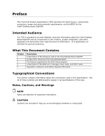
Chapter 1 2 3 4 5 Description A description of the hardware used on the Intel Desktop Board DQ67EP A map of the resources of the Intel Desktop Board The features supported by the BIOS Setup program A description of the BIOS error messages, beep codes, and POST codes Regulatory compliance and - Intel BOXDQ67EP | Product Specification - Page 4
Intel Desktop Board DQ67EP Technical Product Specification Other Common Notation # GB GB/s Gb/s KB Kbit kbits/s MB MB/s Mbit Mbits/s xxh x.x V * TDP Used after a signal name - Intel BOXDQ67EP | Product Specification - Page 5
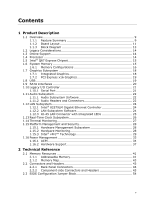
Diagram 13 1.2 Legacy Considerations 14 1.3 Online Support 14 1.4 Processor 14 1.5 Intel® Q67 Express Chipset 15 1.6 System Memory 15 1.6.1 Hardware Monitoring 28 1.15.3 Intel® vPro™ Technology 29 1.16 Power Management 33 1.16.1 ACPI 34 1.16.2 Hardware Support 37 2 Technical Reference 2.1 - Intel BOXDQ67EP | Product Specification - Page 6
DQ67EP Technical Product Specification 2.4 Intel® Management Engine BIOS Extension (Intel® MEBX) Reset Header BIOS Features 3.1 Introduction 63 3.2 System Management BIOS (SMBIOS 65 3.3 Legacy USB Support 65 3.4 BIOS Updates 66 3.4.1 Language Support 66 3.4.2 Custom Splash Screen 67 3.5 BIOS - Intel BOXDQ67EP | Product Specification - Page 7
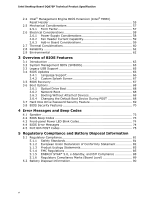
in Figure 1 12 3. Supported Memory Configurations 16 4. LAN Processor Core Power Connector 50 20. Main Power Connector 50 21. Front Panel Header 51 22. States for a One-Color Power LED 52 23. Alternate Front Panel Power LED Header 52 24. BIOS Setup Configuration Jumper Settings 55 25. Intel - Intel BOXDQ67EP | Product Specification - Page 8
Intel Desktop Board DQ67EP Technical Product Specification 28. Thermal Considerations for Components 61 29. Environmental Specifications 62 30. BIOS Setup Program Menu Bar 64 31. BIOS Setup Program Function Keys 64 32. Acceptable Drives/Media Types for BIOS Recovery 67 33. Boot Device Menu - Intel BOXDQ67EP | Product Specification - Page 9
170.18 millimeters by 170.18 millimeters]) • Intel® Core™ i7, Intel® Core™ i5, Intel® Core™ i3, and Intel® Pentium® processors in an LGA1155 socket with up to 95 W TDP: ― Integrated graphics processing (processors with Intel® Graphics Technology) ― External graphics interface controller ― Integrated - Intel BOXDQ67EP | Product Specification - Page 10
pin header for the processor fan • 4-wire and 3-wire (linear) fan speed control support for the system fan • Support for Platform Environmental Control Interface (PECI) • Intel® Advanced Management Technology (Intel® AMT) 7.0 • Intel® Trusted Execution Technology (Intel® TXT) • Intel® Fast Call for - Intel BOXDQ67EP | Product Specification - Page 11
Product Description 1.1.2 Board Layout Figure 1 shows the location of the major components on Intel Desktop Board DQ67EP. Figure 1. Major Board Components Table 2 lists the components identified in Figure 1. 11 - Intel BOXDQ67EP | Product Specification - Page 12
Serial port header D 12 V internal power connector (ATX12V) E Intel Q67 Express Chipset F SATA connectors G Front panel USB 2.0 header H W LGA1155 processor socket X PCI Express x16 add-in card connector Y Processor fan header Z Intel® Management Engine BIOS Extension (Intel® MEBX - Intel BOXDQ67EP | Product Specification - Page 13
Product Description 1.1.3 Block Diagram Figure 2 is a block diagram of the major functional areas of the board. Figure 2. Block Diagram 13 - Intel BOXDQ67EP | Product Specification - Page 14
.intel.com http://www.intel.com/support/motherboards/desktop/sb/CS025414.htm http://www.intel.com/support/go/buildit 1.4 Processor The board is designed to support the Intel Core i7, Intel Core i5, Intel Core i3, and Intel Pentium processors in an LGA1155 socket. Other processors may be supported - Intel BOXDQ67EP | Product Specification - Page 15
board. 1.5 Intel® Q67 Express Chipset The Intel Q67 Express Chipset consisting of the Intel Q67 Platform Controller Hub (PCH) provides interfaces to the processor and the be populated with DIMMs that support the Serial Presence Detect (SPD) data structure. This allows the BIOS to read the SPD data - Intel BOXDQ67EP | Product Specification - Page 16
). For information about... Tested Memory Refer to: http://support.intel.com/support/motherboards/desktop/sb/CS025414.htm 1.6.1 Memory Configurations The Intel Core i7, Intel Core i5, Intel Core i3, and Intel Pentium processors support the following types of memory organization: • Dual channel - Intel BOXDQ67EP | Product Specification - Page 17
Product Description Figure 3 illustrates the memory channel and DIMM configuration. Figure 3. Memory Channel and DIMM Configuration 17 - Intel BOXDQ67EP | Product Specification - Page 18
in graphics card. 1.7.1 Integrated Graphics The board supports integrated graphics through the Intel® Flexible Display Interface (Intel® FDI) for processors with Intel Graphics Technology. NOTE If using a processor with integrated graphics, the board will support only two of the integrated graphics - Intel BOXDQ67EP | Product Specification - Page 19
Intel Core i7, Intel Core i5, Intel Core i3, and Intel Pentium processors in an LGA1155 socket support discrete add in graphics cards through the PCI Express 2.0 x16 graphics connector: • Supports supports up to ten USB 2.0 ports and two USB 3.0 ports. The Intel Q67 USB 3.0 driver support from the - Intel BOXDQ67EP | Product Specification - Page 20
45 1.9.1.1 Serial ATA RAID The board supports the Intel Rapid Storage Technology (Intel RST) which provides the following RAID (Redundant supported RAID features, you must first enable RAID in the BIOS. Also, during Microsoft Windows XP installation, you must press F6 to install the RAID drivers - Intel BOXDQ67EP | Product Specification - Page 21
master drive. For information about Intel Rapid Recovery Technology Refer to http://www.intel.com/support/chipsets/ imsm/sb/CS-026142. pin header on the board. The serial port supports data transfers at speeds up to 115.2 kbits/s with BIOS support. For information about The location of the serial - Intel BOXDQ67EP | Product Specification - Page 22
supports Intel High Definition Audio through the Realtek ALC888S audio codec as well as the DisplayPort interface. The Realtek ALC888S-based audio subsystem supports and drivers are available from Intel's World Wide Web site. For information about Obtaining audio software and drivers Refer to - Intel BOXDQ67EP | Product Specification - Page 23
The back panel audio connectors are configurable through the audio device drivers. For information about The back panel audio connectors Refer to Section 2.2.1, page 44 The front panel headphone output is supported using a separate audio channel pair allowing multi-streaming audio configurations - Intel BOXDQ67EP | Product Specification - Page 24
offload (for IPv4 and IPv6) • Transmit TCP segmentation • Full device driver compatibility • PCI Express power management support • Intel AMT 7.0 1.12.2 LAN Subsystem Software LAN software and drivers are available from Intel's World Wide Web site. For information about Obtaining LAN software and - Intel BOXDQ67EP | Product Specification - Page 25
Product Description 1.12.3 RJ-45 LAN Connector with Integrated LEDs Two LEDs are built into the RJ-45 LAN connector (shown in Figure 5). Item A B Description Link/Activity LED (green) Link Speed LED (green/yellow) Figure 5. LAN Connector LED Locations Table 4 describes the LED states when the - Intel BOXDQ67EP | Product Specification - Page 26
Intel Desktop Board DQ67EP Technical Product Specification 1.13 Real-Time Clock Subsystem A reset and the user will be notified during POST. When the voltage drops below a certain level, the BIOS Setup program settings stored in CMOS RAM (for example, the date and time) might not be accurate. - Intel BOXDQ67EP | Product Specification - Page 27
Description 1.14 Thermal Monitoring Figure 6 shows the locations of the thermal sensors and fan headers. Item A B C D Description Thermal diode, located on Intel Q67 PCH System fan header Thermal diode, located on processor die Processor fan header Figure 6. Thermal Sensors and Fan Headers 27 - Intel BOXDQ67EP | Product Specification - Page 28
supports the following: • Processor and system ambient temperature monitoring • Chassis fan speed monitoring • Power monitoring of +12 V, +5 V, +3.3 V, V_SM, and +VCCP • SMBus interface 1.15.2.1 Fan Monitoring Fan monitoring can be observed through the BIOS setup user interface, Intel - Intel BOXDQ67EP | Product Specification - Page 29
1.15.3 Intel® vPro™ Technology Intel® vPro™ Technology is a set of processor and platform capabilities designed to enable greater proactive security, enhanced maintenance, and improved remote management both inside and outside the corporate firewall. These include: • Intel Active Management - Intel BOXDQ67EP | Product Specification - Page 30
Intel Desktop Board DQ67EP Technical Product Specification • Remote troubleshooting tracking that eliminates time-consuming manual inventory tracking, which also OEM BIOS/Firmware image that provides the Intel Intel AMT-trusted certificate as well as use a remote management application that supports - Intel BOXDQ67EP | Product Specification - Page 31
discontinue the remote access through on-screen pop-up windows. The maximum resolution supported by KVM Remote Control is 1920 x 1200. NOTE KVM Remote Control requires the use of an Intel® processor with integrated graphics. If using simultaneous integrated graphics and add-in PCI Express Graphics - Intel BOXDQ67EP | Product Specification - Page 32
the device. NOTE Requires an Intel processor that supports Intel VT. 1.15.3.5 Intel® Fast Call for Help (Intel® FCFH) Intel Fast Call for Help supplies remote maintenance connectivity for the Enterprise user inside or outside the corporate firewall. Coupled with your enterprise's Management - Intel BOXDQ67EP | Product Specification - Page 33
-usa.com/ 1.16 Power Management Power management is implemented at several levels, including: • Software support through Advanced Configuration and Power Interface (ACPI) • Hardware support: ⎯ Power connector ⎯ Fan headers ⎯ LAN wake capabilities ⎯ Instantly Available PC technology ⎯ Wake from USB - Intel BOXDQ67EP | Product Specification - Page 34
an operating system that provides full ACPI support. ACPI features include: • Plug and Play (including bus and device enumeration) • Power management control of individual devices, add-in boards (some add-in boards may require an ACPI-aware driver), video displays, and hard disk drives • Methods - Intel BOXDQ67EP | Product Specification - Page 35
No power to the system. Service can be performed safely. supported by the BIOS, it is included for reference only. NOTE In order to support processor Deep Sx states, ME Power Package 1 (ME On in S0) must be selected in the BIOS setup. However, this will disable Intel AMT Out-of-Band (OOB) support - Intel BOXDQ67EP | Product Specification - Page 36
Intel Desktop Board DQ67EP Technical Product Specification 1.16.1.2 Wake-up Devices and Events Table 7 lists these wake-up events from an ACPI state requires an operating system that provides full ACPI support. In addition, software, drivers, and peripherals must fully support ACPI wake events. 36 - Intel BOXDQ67EP | Product Specification - Page 37
from an ACPI state requires an operating system that provides full ACPI support. 1.16.2.1 Power Connector ATX12V-compliant power supplies can turn off the 's response can be set using the Last Power State feature in the BIOS Setup program's Boot menu. For information about The location of the main - Intel BOXDQ67EP | Product Specification - Page 38
Intel Desktop Board DQ67EP Technical Product Specification 1.16.2.2 Fan Headers The header is wired to a fan tachometer input of the hardware monitoring and fan control ASIC • All fan headers support closed-loop fan control that can adjust the fan speed or switch the fan on or off as needed • All - Intel BOXDQ67EP | Product Specification - Page 39
is off and the front panel power LED will behave as configured by the BIOS "S3 State Indicator" option). When signaled by a wake-up device or use of Instantly Available PC technology requires operating system support, PCI Express add-in cards, and drivers. 1.16.2.5 Wake from USB USB bus activity - Intel BOXDQ67EP | Product Specification - Page 40
Intel Desktop Board DQ67EP Technical Product Specification 1.16.2.8 +5 V Standby Power LED The green +5 V standby power indicator LED shows that power is still present even when the - Intel BOXDQ67EP | Product Specification - Page 41
16 GB of addressable system memory. Typically the address space that is allocated for PCI Conventional bus add-in cards, PCI Express configuration space, BIOS (SPI Flash device), and chipset overhead resides above the top of DRAM (total system memory). On a system that has 16 GB of system memory - Intel BOXDQ67EP | Product Specification - Page 42
Intel Desktop Board DQ67EP Technical Product Specification Figure 8. Detailed System Memory Address Map 42 - Intel BOXDQ67EP | Product Specification - Page 43
Potential available high DOS memory (open to the Conventional PCI bus). Dependent on video adapter used. Video memory and BIOS Extended BIOS data (movable by memory manager software) Extended conventional memory Conventional memory 2.2 Connectors and Headers CAUTION Only the following connectors - Intel BOXDQ67EP | Product Specification - Page 44
Intel Desktop Board DQ67EP Technical Product Specification 2.2.1 Back Panel Connectors Figure 9 shows the location of the back panel connectors for the board. Item A B C D E F G H I J K Description LAN USB 3.0 - Intel BOXDQ67EP | Product Specification - Page 45
Technical Reference 2.2.2 Component-side Connectors and Headers Figure 10 shows the locations of the component-side connectors and headers. Figure 10. Component-side Connectors and Headers Table 9 lists the component-side connectors and headers identified in Figure 10. 45 - Intel BOXDQ67EP | Product Specification - Page 46
USB 2.0 header Front panel header Alternate front panel power LED header Intel FCFH header LPC Debug connector Chassis intrusion header PCI Express x16 add-in card connector Processor fan header Q S/PDIF header R Intel MEBX reset header S Internal mono speaker header T Front panel audio - Intel BOXDQ67EP | Product Specification - Page 47
3 Key (no pin) 3 +5V_DC Table 12. Internal Mono Speaker Header Pin Signal Name 1 − 2 + Table 13. Front Panel Audio Header for Intel HD Audio Pin Signal Name Pin Signal Name 1 [Port 1] Left channel 3 [Port 1] Right channel 5 [Port 2] Right channel 7 SENSE_SEND (Jack detection - Intel BOXDQ67EP | Product Specification - Page 48
Intel Desktop Board DQ67EP Technical Product Specification Table 14. Front Panel Audio KEY (no pin) 9 FP_OUT_L 10 FP_RETURN_L NOTE Not all AC '97 signals are supported; specifically, pins 4, 6, 7, and 10 are not supported. Table 15. Front Panel USB Header Pin Signal Name Pin 1 +5 VDC 2 - Intel BOXDQ67EP | Product Specification - Page 49
Table 17. Chassis Intrusion Header Pin Signal Name 1 Intruder# 2 Ground Table 18. Processor and System Fan Headers Pin 4-Wire Support Pin 3-Wire Support 1 Ground 3 Ground 2 +12 V 2 FAN_POWER 3 FAN_TACH 1 FAN_TACH 4 FAN_CONTROL N/A N/A 2.2.2.2 Add-in Card Connectors The - Intel BOXDQ67EP | Product Specification - Page 50
previously used on Intel Desktop boards. The board supports the use of ATX12V power supplies with either 2 x 10 or 2 x 12 main power cables. When using a power supply with a 2 x 10 main power cable, pins 11, 12, 23, and 24 must remain unconnected. • Processor core power - a 2 x 2 connector. This - Intel BOXDQ67EP | Product Specification - Page 51
Technical Reference 2.2.2.4 Front Panel Header This section describes the functions of the front panel header. Table 21 lists the signal names of the front panel header. Figure 11 is a connection diagram for the front panel header. Table 21. Front Panel Header Pin Signal In/ Out Description - Intel BOXDQ67EP | Product Specification - Page 52
Intel Desktop Board DQ67EP Technical Product Specification 2.2.2.4.2 Reset Switch Header Pins 5 and two-color LED. Table 22 shows the default states for this LED. More options are available through BIOS setup. Table 22. States for a One-Color Power LED LED State Description Off Power off/ - Intel BOXDQ67EP | Product Specification - Page 53
high-speed USB devices. Figure 12. Connection Diagram for Front Panel USB Headers 2.2.2.7 Low Pin Count (LPC) Debug Connector During the POST, the BIOS generates diagnostic progress codes (POST codes) to I/O port 80h. If the POST fails, execution stops and the last POST code generated is left at - Intel BOXDQ67EP | Product Specification - Page 54
Intel Desktop Board DQ67EP Technical Product Specification 2.3 BIOS Configuration Jumper Block CAUTION Do not Figure 13 shows the location of the jumper block. The 3-pin jumper block determines the BIOS Setup program's mode. Table 25 describes the jumper settings for the three modes: normal, - Intel BOXDQ67EP | Product Specification - Page 55
configuration. A recovery CD or USB flash drive is required. 2.4 Intel® Management Engine BIOS Extension (Intel® MEBX) Reset Header The Intel® MEBX reset header (see Figure 14) allows you to reset the Intel AMT configuration to the factory defaults. Momentarily shorting pins 1 and 2 with a jumper - Intel BOXDQ67EP | Product Specification - Page 56
Intel Desktop Board DQ67EP Technical Product Specification Figure 14. Intel MEBX Reset Header Table 26. Intel MEBX Reset Header Signals Pin Function 1 PCH.AK24 (PCH_RTCRST_PULLUP) 2 Ground 3 No connection 56 - Intel BOXDQ67EP | Product Specification - Page 57
Technical Reference 2.5 Mechanical Considerations 2.5.1 Form Factor The board is designed to fit into a Mini-ITX form-factor chassis. Figure 15 illustrates the mechanical form factor for the board. Dimensions are given in inches [millimeters]. The outer dimensions are 6.7 inches by 6.7 inches [170. - Intel BOXDQ67EP | Product Specification - Page 58
example, for a system consisting of a supported 95 W processor (see Section 1.4 on page 14 for information on supported processors), 2 GB DDR3 RAM, one high For information about Selecting an appropriate power supply Refer to http://www.intel.com/support/motherboards/desktop/sb/C S-026472.htm 58 - Intel BOXDQ67EP | Product Specification - Page 59
. Table 28 lists the current capability of the fan headers. Table 28. Fan Header Current Capability Fan Header Maximum Available Current Processor fan System fan 2.0 A 1.5 A 2.6.3 Add-in Board Considerations The board is designed to provide 2 A (average) of current for each add-in board - Intel BOXDQ67EP | Product Specification - Page 60
remains solely with the reader. Intel makes no warranties or representations that merely following the instructions presented in this document will result Section 2.9. CAUTION Ensure that proper airflow is maintained in the processor voltage regulator circuit. Failure to do so may result in damage - Intel BOXDQ67EP | Product Specification - Page 61
Technical Reference Figure 16 shows the locations of the localized high temperature zones. Item A B C Description Processor voltage regulator area Processor Intel Q67 Express Chipset Figure 16. Localized High Temperature Zones Table 29 provides maximum case temperatures for the components that - Intel BOXDQ67EP | Product Specification - Page 62
Intel Desktop Board DQ67EP Technical Product Specification 2.8 Reliability The Mean Time Between Failures (MTBF) prediction is calculated using component and subassembly random failure rates. The calculation - Intel BOXDQ67EP | Product Specification - Page 63
The board uses an Intel BIOS that is stored in a 64 Mbit (8,192 KB) Serial Peripheral Interface Flash Memory (SPI Flash) device which can be updated using a set of utilities. The SPI Flash contains the BIOS Setup program, POST, LAN EEPROM information, Plug and Play support, and other firmware. The - Intel BOXDQ67EP | Product Specification - Page 64
Table 31 lists the BIOS Setup program menu features. Table 31. BIOS Setup Program Menu Bar Maintenance Main Configura- tion Performance Security Power Boot Intel ME Exit Clears passwords and displays processor information Displays processor and memory configuration Configures - Intel BOXDQ67EP | Product Specification - Page 65
and processor speed • Dynamic data, such as event detection and error logging Non-Plug and Play operating systems require an additional interface for obtaining the SMBIOS information. The BIOS supports an SMBIOS table interface for such operating systems. Using this support, an SMBIOS service-level - Intel BOXDQ67EP | Product Specification - Page 66
an incompatible BIOS. NOTE Review the instructions distributed with the upgrade utility before attempting a BIOS update. For information about BIOS update utilities Refer to http://www.intel.com/support/motherboards/desktop/sb/CS022312.htm. 3.4.1 Language Support The BIOS Setup program - Intel BOXDQ67EP | Product Specification - Page 67
diskette) No USB hard disk drive No Legacy diskette drive (with a 1.44 MB diskette) connected to the No legacy diskette drive interface For information about BIOS recovery Refer to http://www.intel.com/support/motherboards/desktop/sb/ cs-023360.htm 67 - Intel BOXDQ67EP | Product Specification - Page 68
Intel Desktop Board DQ67EP Technical Product Specification 3.6 Boot Options In the BIOS Setup program, the user can Booting from the optical drive is supported in compliance to the El Torito bootable CD-ROM format specification. Under the Boot menu in the BIOS Setup program, the optical drive - Intel BOXDQ67EP | Product Specification - Page 69
are set in BIOS SETUP and are prompted for during BIOS POST. For convenient support of S3 resume, the system BIOS will automatically unlock drives A manual power cycle will be required to resume system operation. NOTE As implemented on DQ67EP, Hard Disk Drive Password Security is only supported on - Intel BOXDQ67EP | Product Specification - Page 70
Intel Desktop Board DQ67EP Technical Product Specification NOTE Hard Disk Drive Password Security is not supported in PCH RAID mode. Secured hard disk drives attached to the system when the system is in PCH RAID mode will not be accessible due to the disabling of BIOS Hard Disk Drive Password - Intel BOXDQ67EP | Product Specification - Page 71
Overview of BIOS Features Table 36 shows the effects of setting the supervisor password and user password. This table is for reference only and is not displayed on - Intel BOXDQ67EP | Product Specification - Page 72
Intel Desktop Board DQ67EP Technical Product Specification 72 - Intel BOXDQ67EP | Product Specification - Page 73
problem (see Table 37). Table 37. BIOS Beep Codes Type Pattern F2 Setup/F10 Boot Menu One 0.5 second beep when BIOS is ready to Prompt accept keyboard input BIOS Frequency/Comments 932 Hz 932 Hz For processors requiring an add-in graphics card 932 Hz High beep 2000 Hz Low beep 1500 Hz - Intel BOXDQ67EP | Product Specification - Page 74
Intel Desktop Board DQ67EP Technical Product Specification 4.3 Front-panel Power LED Blink Codes Whenever a recoverable error occurs during POST, the BIOS causes the board's front panel power LED to blink an error message describing the problem processors requiring an add-in graphics card 4.4 BIOS - Intel BOXDQ67EP | Product Specification - Page 75
provide information about the POST codes generated by the BIOS: • Table 40 lists the Port 80h POST code post MRC execution Recovery Platform DXE driver CPU Initialization (PEI, DXE, SMM) I/O Buses: PCI, an unrecoverable error. Start with PCI. BDS Output devices: All output consoles. For future - Intel BOXDQ67EP | Product Specification - Page 76
Intel Desktop Resuming from S2, S3, S4, S5 Security Phase (SEC) 0x08 Starting BIOS execution after CPU BIST 0x09 SPI prefetching and caching 0x0A Load BSP microcode 0x0B 0x0F Pass entry point of the PEI core PEI before MRC PEI Platform driver 0x11 Set bootmode, GPIO init 0x12 Early - Intel BOXDQ67EP | Product Specification - Page 77
CPU Initialization CPU PEI Phase 0x41 Begin CPU PEI Init 0x42 XMM instruction enabling 0x43 End CPU PEI Init CPU PEI SMM Phase 0x44 Begin microcode if needed 0x4A Initialize strings to HII database 0x4B Initialize MP support 0x4C CPU DXE Phase End CPU DXE SMM Phase 0x4D CPU DXE - Intel BOXDQ67EP | Product Specification - Page 78
Intel Desktop Board DQ67EP Technical Product Specification Table 41. Port 80h POST Codes (continued) Port 80 Code Progress Code Enumeration BDS 0x60 BDS driver entry point initialize 0x61 BDS service routine entry point (can be called multiple times) 0x62 BDS Step2 0x63 BDS Step3 0x64 - Intel BOXDQ67EP | Product Specification - Page 79
0xBB Enabling/configuring a removable media DXE Core 0xE4 Entered DXE phase BDS 0xE7 Waiting for user input 0xE8 Checking password 0xE9 Entering BIOS setup 0xEB Calling Legacy Option ROMs Runtime Phase/EFI OS Boot 0xF8 EFI boot service ExitBootServices ( ) has been called 0xF9 EFI - Intel BOXDQ67EP | Product Specification - Page 80
Intel Desktop Board capsule E4 Entered DXE phase 12 Starting application processor initialization 13 SMM initialization 50 Enumerating PCI buses Clearing keyboard input buffer 95 Keyboard Self Test EB Calling Video BIOS 58 Resetting USB bus 5A Resetting PATA/SATA bus and all - Intel BOXDQ67EP | Product Specification - Page 81
Declaration of Conformity statement • Product Ecology statements • Electromagnetic Compatibility (EMC) standards • Product certification markings 5.1.1 Safety Standards The Intel Desktop Board DQ67EP complies with the safety standards stated in Table 43 when correctly installed in a compatible host - Intel BOXDQ67EP | Product Specification - Page 82
Desktop Board DQ67EP Technical Product Specification 5.1.2 European Union Declaration of Conformity Statement We, Intel Corporation, declare under our sole responsibility that the product Intel® Desktop Board DQ67EP is in conformity with all applicable essential requirements necessary for CE - Intel BOXDQ67EP | Product Specification - Page 83
of this program, including the scope of covered products, available locations, shipping instructions, terms and conditions, etc Intel Product Recycling Program http://www.intel.com/intel/other/ehs/product_ecology Deutsch Als Teil von Intels Engagement für den Umweltschutz hat das Unternehmen das - Intel BOXDQ67EP | Product Specification - Page 84
pour en savoir plus sur ce programme, à savoir les produits concernés, les adresses disponibles, les instructions d'expédition, les conditions générales, etc http://www.intel.com/in tel/other/ehs/product_ecology Malay Sebagai sebahagian daripada komitmennya terhadap tanggungjawab persekitaran - Intel BOXDQ67EP | Product Specification - Page 85
nakliye talimatları, kayıtlar ve şartlar v.s dahil bütün ayrıntılarını ögrenmek için lütfen http://www.intel.com/intel/other/ehs/product_ecology Web sayfasına gidin. 5.1.4 EMC Regulations The Intel Desktop Board DQ67EP complies with the EMC regulations stated in Table 44 when correctly installed in - Intel BOXDQ67EP | Product Specification - Page 86
and, if not installed and used in accordance with the instructions, may cause harmful interference to radio communications. However, there . Any changes or modifications to the equipment not expressly approved by Intel Corporation could void the user's authority to operate the equipment. Tested to - Intel BOXDQ67EP | Product Specification - Page 87
or television receiver in a domestic environment, it may cause radio interference. Install and use the equipment according to the instruction manual. Korea Class B Statement Korea Class B Statement translation: This equipment is for home use, and has acquired electromagnetic conformity registration - Intel BOXDQ67EP | Product Specification - Page 88
Electronic Product Environmental Assessment Tool (EPEAT) Korea e-Standby Program European Union Energy-related Products Directive 2009 (ErP) Refer to http://www.intel.com/go/energystar http://www.epeat.net/ http://www.kemco.or.kr/new_eng/pg02/ pg02100300.asp http://ec.europa.eu/enterprise/policies - Intel BOXDQ67EP | Product Specification - Page 89
along with a flammability rating (solder side). China RoHS/Environmentally Friendly Use Period Logo: This is an example of the symbol used on Intel Desktop Boards and associated collateral. The color of the mark may vary depending upon the application. The Environmental Friendly Usage Period (EFUP - Intel BOXDQ67EP | Product Specification - Page 90
Intel Desktop Board DQ67EP Technical Product Specification 5.2 Battery Disposal Information CAUTION Risk of explosion if the battery is replaced with an incorrect type. Batteries should be - Intel BOXDQ67EP | Product Specification - Page 91
Regulatory Compliance and Battery Disposal Information PRECAUCIÓN Existe peligro de explosión si la pila no se cambia de forma adecuada. Utilice solamente pilas iguales o del mismo tipo que las recomendadas por el fabricante del equipo. Para deshacerse de las pilas usadas, siga igualmente las - Intel BOXDQ67EP | Product Specification - Page 92
Intel Desktop Board DQ67EP Technical Product Specification AWAS Risiko letupan wujud jika bateri digantikan dengan jenis yang tidak betul. Bateri sepatutnya dikitar semula jika boleh. Pelupusan - Intel BOXDQ67EP | Product Specification - Page 93
Regulatory Compliance and Battery Disposal Information 93 - Intel BOXDQ67EP | Product Specification - Page 94
Intel Desktop Board DQ67EP Technical Product Specification 94
-
 1
1 -
 2
2 -
 3
3 -
 4
4 -
 5
5 -
 6
6 -
 7
7 -
8
-
9
-
10
-
11
-
12
-
13
-
14
-
15
-
16
-
17
-
18
-
19
-
20
-
21
-
22
-
23
-
24
-
25
-
26
-
27
-
28
-
29
-
30
-
31
-
32
-
33
-
34
-
35
-
36
-
37
-
38
-
39
-
40
-
41
-
42
-
43
-
44
-
45
-
46
-
47
-
48
-
49
-
50
-
51
-
52
-
53
-
54
-
55
-
56
-
57
-
58
-
59
-
60
-
61
-
62
-
63
-
64
-
65
-
66
-
67
-
68
-
69
-
70
-
71
-
72
-
73
-
74
-
75
-
76
-
77
-
78
-
79
-
80
-
81
-
82
-
83
-
84
-
85
-
86
-
87
-
88
-
89
-
90
-
91
-
92
-
93
-
94
 |
 |

Intel® Desktop Board
DQ67EP
Technical Product Specification
January 2011
Order Number:
G15493-001US
The Intel
®
Desktop Board DQ67EP may contain design defects or errors known as errata that may cause the product to deviate from published
specifications.
Current characterized errata are documented in the Intel Desktop Board DQ67EP Specification Update.