Intel DBS1200KP Product Guide
Intel DBS1200KP Manual
 |
View all Intel DBS1200KP manuals
Add to My Manuals
Save this manual to your list of manuals |
Intel DBS1200KP manual content summary:
- Intel DBS1200KP | Product Guide - Page 1
Intel® Server Board S1200KP Product Guide Order Number: G39481-003 - Intel DBS1200KP | Product Guide - Page 2
1-800-548-4725. Intel, Intel Core, and Pentium are trademarks of Intel Corporation in the United States and other countries. * Other names and brands may be claimed as the property of others. Copyright © 2012, Intel Corporation. All rights reserved. ii Intel® Server Board S1200KP Product Guide - Intel DBS1200KP | Product Guide - Page 3
by Intel®. Document Organization The chapters in this Product Guide are arranged as follows: 1 Server Board Features: a summary of product features 2 Installing and Replacing Server Board Components: instructions on how to install the Server Board and other hardware components 3 Updating the BIOS - Intel DBS1200KP | Product Guide - Page 4
Preface Term MB Mb MHz Description Megabyte (1,048,576 bytes) Megabit (1,048,576 bits) Megahertz (one million hertz) iv Intel® Server Board S1200KP Product Guide - Intel DBS1200KP | Product Guide - Page 5
iii Conventions...iii Terminology ...iii 1 Server Board Features...1 Supported Operating Systems 3 Server Board Components ...4 Processor ...6 Intel® C206 Express Chipset 7 Main Memory ...7 Graphics Subsystem ...8 Integrated Graphics ...8 Intel® HD Graphics 8 Digital Visual Interface - Intel DBS1200KP | Product Guide - Page 6
BIOS Update File 43 Updating the BIOS with the Intel® Flash Memory Update Utility 43 Updating the BIOS Using the F7 Function Key 45 Recovering the BIOS 45 Appendix A: Error Messages and Indicators 46 BIOS Error Codes ...46 BIOS Error Messages ...47 vi Intel® Server Board S1200KP Product Guide - Intel DBS1200KP | Product Guide - Page 7
25 Figure 11. Connecting the Processor Fan Heat Sink Power Cable to the Processor Fan Header ...26 Figure 12. Dual Channel Memory Configuration Example 27 Figure 13. of the BIOS Configuration Jumper Block 39 Figure 22. Removing the Battery 42 Intel® Server Board S1200KP Product Guide vii - Intel DBS1200KP | Product Guide - Page 8
Front Panel Power LED Header Signal Names 35 Table 8. LPC Debug Header 36 Table 9. Jumper Settings for the BIOS Setup Program Modes 40 Table 10. BIOS Beep Codes 46 Table 11. Front-panel Power LED Blink Codes 46 Table 12. BIOS Error Messages 47 viii Intel® Server Board S1200KP Product Guide - Intel DBS1200KP | Product Guide - Page 9
Tables Intel® Server Board S1200KP Product Guide ix - Intel DBS1200KP | Product Guide - Page 10
describes the features of Intel® Server Board S1200KP. Table 1 summarizes the major features of the Server Board. Feature Form Factor Processor Memory Chipset Graphics Peripheral Interfaces Expansion Capabilities BIOS Table 1. Feature Summary Description Mini-ITX (6.7 inches by 6.7 inches [170 - Intel DBS1200KP | Product Guide - Page 11
DBS1200KPR and BBS1200KPR can support Intel® Xeon® E3-1200 Processors, the 2nd Generation Intel® Core™ i3 Processors, Intel® Xeon® E3-1200 V2 Processors or the 3rd Generation Intel® Core™ i3 Processors. ECC DIMMS are recommended to use for server system. 2 Intel® Server Board S1200KP Product Guide - Intel DBS1200KP | Product Guide - Page 12
Server Board Features Supported Operating Systems The Server Board provides full support for the Server 2008 R2 SP1* with Hyper-v Microsoft Windows Small Business Server 2011 Essentials* Redhat* Enterprise Linux 6.0 SUSE* Linux Enterprise Server 11 Intel® Server Board S1200KP Product Guide - Intel DBS1200KP | Product Guide - Page 13
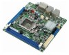
Server Board Features Server Board Components Figure 1 shows the approximate location of the major components on Intel® Server Board S1200KP. Figure 1. Intel® Server Board S1200KP Components 4 Intel® Server Board S1200KP Product Guide - Intel DBS1200KP | Product Guide - Page 14
Server Board Features Table 2. Intel® Server Board S1200KP Components Item/callout A B C D E F G H I J K L M N O P Q R S T U Description Back panel connectors Processor core power connector (2 x 2) Front panel USB 2.0 header BIOS Setup configuration jumper block SATA connectors Intel® C206 - Intel DBS1200KP | Product Guide - Page 15
on Intel® Server Board S1200KP consult the following online resources: Intel® Server Board S1200KP http://www.intel.com/products/server Supported processors and tested memory http://serverconfigurator.intel.com BIOS and driver updates http://downloadcenter.intel.com Processor CAUTION - Intel DBS1200KP | Product Guide - Page 16
Detect Support for DDR3 1066/1333 MHz (with Intel® Xeon® E3-1200 Processors or the 2nd Generation Intel® Core™ i3 Processors) or DDR3 1333/1600 MHz (with Intel® Xeon® E3-1200 V2 Processors or the 3rd Generation Intel® Core™ i3 Processors) DIMMs Intel® Server Board S1200KP Product Guide 7 - Intel DBS1200KP | Product Guide - Page 17
1200 Processors or the 2nd Generation Intel® Core™ i3 Processors in an LGA1155 socket support discrete add in graphics cards via the PCI Express* 2.0 x16 graphics connector. And the Intel® Xeon® E3-1200 V2 Processors or the 3rd Generation Intel® Core™ i3 8 Intel® Server Board S1200KP Product Guide - Intel DBS1200KP | Product Guide - Page 18
Supports PCI Express* GEN1 frequency of 2.5 GHz resulting in 2.5 Gb/s each direction (250 MB/s) per lane. The maximum theoretical bandwidth on the interface is 4 GB/s in each direction, simultaneously, for an aggregate of 8 GB/s when operating in x16 GEN1 mode. Intel® Server Board S1200KP Product - Intel DBS1200KP | Product Guide - Page 19
capable. USB 2.0 support requires both an operating system and drivers that fully support USB 2.0 transfer rates. SATA Support Intel® Server Board S1200KP provides two onboard 6.0 Gb/s Serial ATA (SATA) channels and two onboard 3.0 Gb/s SATA channels. 10 Intel® Server Board S1200KP Product Guide - Intel DBS1200KP | Product Guide - Page 20
Server Board Features Expandability Intel® Server Board S1200KP provides one PCI Express* 2.0 x16 (with Intel® Xeon® E3-1200 Processors or the 2nd Generation Intel® Core™ i3 Processors) or PCI Express* 3.0 x 16 (with Intel® Xeon® E3-1200 V2 Processors or the 3rd Generation Intel® Core™ i3 Processors - Intel DBS1200KP | Product Guide - Page 21
you can enter either password to boot the computer. For instructions on resetting the password, go to Clearing Passwords on page 40. Hardware Management The hardware management features of Intel® Server Board S1200KP enable the board to be compatible with the Wired for Management (WfM) specification - Intel DBS1200KP | Product Guide - Page 22
signal support Software Support ACPI ACPI gives the operating system direct control over the power management and Plug and Play functions of a computer. The use of ACPI with the Server Board requires an operating system that provides full ACPI support. Intel® Server Board S1200KP Product Guide 13 - Intel DBS1200KP | Product Guide - Page 23
using the Last Power State feature in the BIOS Setup program's Boot menu. The Server Board has two power connectors. See Figure 20 The chassis fan header supports linear fan control on 3-wire fans. The Server Board has a 4-pin processor fan header and two 4- Intel® Server Board S1200KP Product Guide - Intel DBS1200KP | Product Guide - Page 24
in Figure 3, is lit when there is standby power still present on the board even when the computer appears to be off. For example, when this green LED is lit, standby power is still present at the memory module sockets and the PCI Express* connector. Intel® Server Board S1200KP Product Guide 15 - Intel DBS1200KP | Product Guide - Page 25
Server Board Features Figure 3. Location of the Standby Power Indicator For more information on standby current requirements for the Server Board, refer to the Technical Product Specification at http://www.intel.com/products/server. 16 Intel® Server Board S1200KP Product Guide - Intel DBS1200KP | Product Guide - Page 26
voltage drops below a certain level, the BIOS Setup program settings stored in CMOS RAM (for example, the date and time) might not be accurate. Replace the battery with an equivalent one. Go to page 41 for instructions on how to replace the battery. Intel® Server Board S1200KP Product Guide 17 - Intel DBS1200KP | Product Guide - Page 27
Board Install and remove a processor Install and remove memory Install and remove a PCI Express* x16 card Connect SATA drives Connect to the internal headers Connect chassis fan and power supply cables Set the BIOS of the computer chassis. 18 Intel® Server Board S1200KP Product Guide - Intel DBS1200KP | Product Guide - Page 28
and regulations. If the instructions for the chassis are inconsistent with these instructions or the instructions for associated modules, contact the supplier to find out how you can ensure that your computer meets safety and regulatory requirements. Intel® Server Board S1200KP Product Guide 19 - Intel DBS1200KP | Product Guide - Page 29
that it fits tightly and securely. If the shield does not fit, obtain a properly sized shield from the chassis supplier. Figure 4. Installing the I/O Shield 20 Intel® Server Board S1200KP Product Guide - Intel DBS1200KP | Product Guide - Page 30
. Refer to your Chassis Manual for instructions on installing and removing the Server Board. Figure 5 shows the location of the mounting screw holes for Intel® Server Board S1200KP. Figure 5. Intel® Server Board S1200KP Mounting Screw Hole Locations Intel® Server Board S1200KP Product Guide 21 - Intel DBS1200KP | Product Guide - Page 31
board. To install a processor, follow these instructions: 1. Observe the precautions in "Before You Begin" in page 18. 2. Unlatch the processor socket lever by pushing it down and away from the socket (Figure 6, A, B). Figure 6. Unlatch the Socket Lever 22 Intel® Server Board S1200KP Product Guide - Intel DBS1200KP | Product Guide - Page 32
Installing and Replacing Server Board Components 3. Rotate the socket lever to lift the load plate away from the socket (Figure 7, A). Make being careful not to damage adjacent components. Do not touch the socket contacts. Figure 7. Lift the Load Plate Intel® Server Board S1200KP Product Guide 23 - Intel DBS1200KP | Product Guide - Page 33
in the socket (Figure 9, A). Figure 9. Install the Processor 6. Carefully lower the socket lever (Figure 10, A) while making sure that the front edge of the load plate slides under the shoulder screw cap as the lever is lowered. Latch the socket lever 24 Intel® Server Board S1200KP Product Guide - Intel DBS1200KP | Product Guide - Page 34
10. Secure the Load Plate in Place 7. Pick up the socket cover and remove it from the server board. NOTE Do not discard the socket cover; save it for possible future use. Always replace the socket cover if you remove the processor from the socket. Intel® Server Board S1200KP Product Guide 25 - Intel DBS1200KP | Product Guide - Page 35
11 is recommended. Figure 11. Connecting the Processor Fan Heat Sink Power Cable to the Processor Fan Header Removing the Processor For instructions on how to remove the processor fan heat sink and processor, refer to the processor installation manual. 26 Intel® Server Board S1200KP Product Guide - Intel DBS1200KP | Product Guide - Page 36
NOTE The Intel® Xeon® E3-1200 Processors, the 2nd Generation Intel® Core™ i3 Processors, Intel® Xeon® E3-1200 V2 Processors or the 3rd Generation Intel® Core™ i3 Processors require memory to be installed in the DIMM_A1 (or Channel A, DIMM 1) socket. Intel® Server Board S1200KP Product Guide 27 - Intel DBS1200KP | Product Guide - Page 37
Installing and Replacing Server Board Components Installing DIMMs To make sure you have the correct DIMM, place it on the illustration of the DDR3 DIMM in Figure 13. All the notches should match with the DDR3 DIMM. Figure 13. Use DDR3 DIMMs 28 Intel® Server Board S1200KP Product Guide - Intel DBS1200KP | Product Guide - Page 38
Installing and Replacing Server Board Components To install a DIMM, follow these steps: 1. Observe the precautions in "Before You Begin" on page 18. 2. Turn in the socket (see inset in Figure 14). 8. Insert the bottom edge of the DIMM into the socket. Intel® Server Board S1200KP Product Guide 29 - Intel DBS1200KP | Product Guide - Page 39
Installing and Replacing Server Board Components 9. When the DIMM is inserted, push down on the top edge of the connector pins. Depending on the over-current protection of the power supply, certain Server Board components and/or traces may be damaged. 30 Intel® Server Board S1200KP Product Guide - Intel DBS1200KP | Product Guide - Page 40
connector. 3. Secure the card's metal bracket to the chassis back panel with a screw (Figure 15, B). 4. Connect a monitor to the graphics card according to the manufacturer's instructions. Figure 15. Installing a PCI Express* x16 Graphics Card Intel® Server Board S1200KP Product Guide 31 - Intel DBS1200KP | Product Guide - Page 41
Installing and Replacing Server Board Components Removing a PCI Express* x16 Graphics Card Follow these instructions to remove a PCI Express* x16 graphics card from a connector: 1. Observe remove it. Figure 16. Removing a PCI Express* x16 Graphics Card 32 Intel® Server Board S1200KP Product Guide - Intel DBS1200KP | Product Guide - Page 42
in "Before You Begin" on page 18. 2. Attach one end of the SATA cable to one of the SATA connectors on the board (Figure 17, A) and attach the other end of the cable to the SATA drive data connector (Figure 17, B). Figure 17. Connecting a SATA Drive Intel® Server Board S1200KP Product Guide 33 - Intel DBS1200KP | Product Guide - Page 43
page 18. Figure 18 shows the location of the internal headers and connectors on Intel® Server Board S1200KP. Figure 18. Internal Headers Chassis Intrusion Header Figure 18, A shows the Header Signal Names Pin 1 2 Description Ground Intruder# 34 Intel® Server Board S1200KP Product Guide - Intel DBS1200KP | Product Guide - Page 44
Installing and Replacing Server Board Components Front Panel USB 2.0 Headers Figure 18, B shows the location of the front panel USB 2.0 headers and Header Signal Names Pin 1 2 3 Signal Name Front panel LED+ No pin Front panel LED- In/Out Out Out Intel® Server Board S1200KP Product Guide 35 - Intel DBS1200KP | Product Guide - Page 45
Installing and Replacing Server Board Components Low Pin Count (LPC) Debug header Figure 18, E shows the location of the low Connected Table 8. LPC Debug Header Pin Signal Name 2 GND 4 LFRAME# 6 LAD1 8 LAD3 10 GND 12 +3.3 V 14 +3.3 V 36 Intel® Server Board S1200KP Product Guide - Intel DBS1200KP | Product Guide - Page 46
Connecting Chassis Fan and Power Supply Cables Connecting a Chassis Fan Connect the chassis fan cable to the chassis fan header on the Server Board. Figure 19 shows the location of the chassis fan header. Figure 19. Location of the Chassis Fan Header Intel® Server Board S1200KP Product Guide 37 - Intel DBS1200KP | Product Guide - Page 47
1. Observe the precautions in "Before You Begin" on page 18. 2. Connect the 12 V processor core voltage power supply cable to the 2 x 2 pin connector (Figure 20, A). 3. Connect the main power supply cable to the 2 x 12 pin connector (Figure 20, B). 38 Intel® Server Board S1200KP Product Guide - Intel DBS1200KP | Product Guide - Page 48
before moving the jumper. Moving the jumper with the power on may result in unreliable computer operation. Figure 21 shows the location of the Server Board's BIOS configuration jumper block. Figure 21. Location of the BIOS Configuration Jumper Block Intel® Server Board S1200KP Product Guide 39 - Intel DBS1200KP | Product Guide - Page 49
the BIOS displays the Maintenance Menu. Use this menu to clear passwords. The BIOS recovers data in the event of a failed BIOS update. Clearing Passwords This procedure assumes that the board is operation, place the jumper on pins 1-2 as shown below. 40 Intel® Server Board S1200KP Product Guide - Intel DBS1200KP | Product Guide - Page 50
3.3 VSB applied. When the voltage drops below a certain level, the BIOS Setup program settings stored in CMOS RAM (for example, the date and time) might not be accurate. Replace wires (Figure 22, E) to the server board. 7. Replace the computer cover. Intel® Server Board S1200KP Product Guide 41 - Intel DBS1200KP | Product Guide - Page 51
Installing and Replacing Server Board Components Figure 22. Removing the Battery 42 Intel® Server Board S1200KP Product Guide - Intel DBS1200KP | Product Guide - Page 52
Intel® Flash Memory Update Utility allows you to: Update the BIOS and Intel® Management Engine in flash memory Update the language section of the BIOS NOTE Review the instructions distributed with the update utility before attempting a BIOS update. Intel® Server Board S1200KP Product Guide - Intel DBS1200KP | Product Guide - Page 53
and .ITK file (optional) to a bootable USB flash drive or other bootable USB media. 2. Configure the BIOS or use the F10 option during POST to boot to the USB device. 3. Manually run the IFLASH.EXE file from the USB device and manually update the BIOS. 44 Intel® Server Board S1200KP Product Guide - Intel DBS1200KP | Product Guide - Page 54
supplier or by navigating to the Intel® Server Board S1200KP page on the Intel® World Wide Web site Download Center at http://downloadcenter.intel.com. On the S1200KP page, click on the "BIOS Update" link and then select the Recovery BIOS Update file. Intel® Server Board S1200KP Product Guide 45 - Intel DBS1200KP | Product Guide - Page 55
and Indicators Appendix A: Error Messages and Indicators Intel® Server Board S1200KP reports POST errors in two ways: By sounding a beep code and blinking the front panel power LED By displaying an error message on the monitor BIOS Error Codes Whenever a recoverable error occurs during - Intel DBS1200KP | Product Guide - Page 56
the battery soon. The CMOS checksum is incorrect. CMOS memory may have been corrupted. Run Setup to reset values. Memory size has decreased since the last boot. If no memory was removed, then memory may be bad. System did not find a device to boot. Intel® Server Board S1200KP Product Guide 47
-
 1
1 -
 2
2 -
 3
3 -
 4
4 -
 5
5 -
 6
6 -
 7
7 -
8
-
9
-
10
-
11
-
12
-
13
-
14
-
15
-
16
-
17
-
18
-
19
-
20
-
21
-
22
-
23
-
24
-
25
-
26
-
27
-
28
-
29
-
30
-
31
-
32
-
33
-
34
-
35
-
36
-
37
-
38
-
39
-
40
-
41
-
42
-
43
-
44
-
45
-
46
-
47
-
48
-
49
-
50
-
51
-
52
-
53
-
54
-
55
-
56
 |
 |

Intel
®
Server Board S1200KP
Product Guide
Order Number: G39481-003