Intel KD945GCZKRPAK10 Product Specification
Intel KD945GCZKRPAK10 - 10PK MICRO BTX 1066/800/533 FSB Manual
 |
UPC - 735858174800
View all Intel KD945GCZKRPAK10 manuals
Add to My Manuals
Save this manual to your list of manuals |
Intel KD945GCZKRPAK10 manual content summary:
- Intel KD945GCZKRPAK10 | Product Specification - Page 1
January 2007 Order Number: D80699-001US The Intel® Desktop Board D945GCCR may contain design defects or errors known as errata that may cause the product to deviate from published specifications. Current characterized errata are documented in the Intel Desktop Board D945GCCR Specification Update. - Intel KD945GCZKRPAK10 | Product Specification - Page 2
or characteristics of any features or instructions marked "reserved" or "undefined." Intel reserves these for future definition other Countries 708-296-9333. Intel, the Intel logo, Pentium, Intel Core 2 Duo, and Celeron are registered trademarks of Intel Corporation or its subsidiaries in the United - Intel KD945GCZKRPAK10 | Product Specification - Page 3
and environmental requirements, and the BIOS for the Intel® Desktop Board D945GCCR. It describes the standard product and available of the hardware used on the Desktop Board D945GCCR A map of the resources of the Desktop Board The features supported by the BIOS Setup program A description of - Intel KD945GCZKRPAK10 | Product Specification - Page 4
Intel Desktop Board D945GCCR Technical Product Specification WARNING Warnings indicate conditions , N indicates component type, xn are the relative coordinates of its location on the Desktop Board D945GCCR, and X is the instance of the particular part at that general location. For example, J5J1 - Intel KD945GCZKRPAK10 | Product Specification - Page 5
10 1.1.2 Board Layout 12 1.1.3 Block Diagram 14 1.2 Online Support 15 1.3 Processor 15 1.4 System Memory 16 1.4.1 Memory Configurations 18 1.5 Intel® 945GC Chipset 21 1.5.1 Intel 945GC Graphics Subsystem 21 1.5.2 USB 23 1.5.3 IDE Support 24 1.5.4 Real-Time Clock, CMOS SRAM, and Battery 25 - Intel KD945GCZKRPAK10 | Product Specification - Page 6
Intel Desktop Board D945GCCR Technical Product Specification 2.5 Interrupts 46 2.6 PCI Conventional Interrupt Routing Map 47 PCI IDE Support 71 3.4 System Management BIOS (SMBIOS 71 3.5 BIOS Updates 72 3.5.1 Language Support 72 3.5.2 Custom Splash Screen 72 3.6 Legacy USB Support 73 3.7 Boot - Intel KD945GCZKRPAK10 | Product Specification - Page 7
Block Diagram 14 3. Memory Channel and DIMM Configuration 18 4. Dual Channel (Interleaved) Mode Configuration with Two DIMMs 19 5. Single Feature Summary 10 2. Board Components Shown in Figure 1 13 3. Supported Memory Configurations 16 4. Memory Operating Frequencies 17 5. LAN Connector LED - Intel KD945GCZKRPAK10 | Product Specification - Page 8
Intel Desktop Board D945GCCR Technical Product Specification 15. Component-side Connectors and Headers Shown in Figure 13 51 16. Front Panel Audio Header 52 17. Chassis Intrusion Header 52 18. Serial ATA Connectors 52 19. Processor Fan Header 52 20. Front and Rear Chassis Fan Headers 52 21. - Intel KD945GCZKRPAK10 | Product Specification - Page 9
1 Product Description What This Chapter Contains 1.1 Overview 10 1.2 Online Support 15 1.3 Processor 15 1.4 System Memory 16 1.5 Intel® 945GC Chipset 21 1.6 PCI Express* Connectors 25 1.7 Legacy I/O Controller 26 1.8 Audio Subsystem 27 1.9 LAN Subsystem 29 1.10 Hardware Management Subsystem - Intel KD945GCZKRPAK10 | Product Specification - Page 10
[243.84 millimeters by 243.84 millimeters]) Support for the following: • Intel® Core™2 Duo processor in an LGA775 socket with a 800 MHz system bus • Intel® Pentium® D processor in an LGA775 socket with an 800 or 533 MHz system bus • Intel® Pentium® 4 processor in an LGA775 socket with an 800 or - Intel KD945GCZKRPAK10 | Product Specification - Page 11
Description Table 1. Feature Summary (continued) Instantly Available PC Technology Hardware Monitor Subsystem • Support for PCI Local Bus Specification Revision 2.3 • Support for PCI Express Revision 1.0a • Suspend to RAM support • Wake on PCI, RS-232, front panel, PS/2 devices, and USB ports - Intel KD945GCZKRPAK10 | Product Specification - Page 12
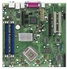
Intel Desktop Board D945GCCR Technical Product Specification 1.1.2 Board Layout Figure 1 shows the location of the major components. Figure 1. Board Components Table 2 lists the components identified in Figure 1. 12 - Intel KD945GCZKRPAK10 | Product Specification - Page 13
connector E PCI Express x16 bus add-in card connector F Back panel connectors G Processor core power connector H Processor fan header I Rear chassis fan header J LGA775 processor socket K Intel 82945GC GMCH L DIMM socket M DIMM socket N Chassis intrusion header O Main Power - Intel KD945GCZKRPAK10 | Product Specification - Page 14
Intel Desktop Board D945GCCR Technical Product Specification 1.1.3 Block Diagram Figure 2 is a block diagram of the major functional areas. Figure 2. Block Diagram 14 - Intel KD945GCZKRPAK10 | Product Specification - Page 15
The board is designed to support the following processors: • Intel Core 2 Duo processor in an LGA775 socket with a 800 MHz system bus • Intel Pentium D processor in an LGA775 processor socket with an 800 or 533 MHz system bus • Intel Pentium 4 processor in an LGA775 processor socket with an 800 or - Intel KD945GCZKRPAK10 | Product Specification - Page 16
Intel Desktop Board D945GCCR Technical Product Specification 1.4 System Memory The board has two DIMM sockets and supports the following memory features: • 1.8 V (only) DDR2 SDRAM DIMMs with gold-plated contacts • Unbuffered, single-sided or double-sided DIMMs with the following restriction: Double - Intel KD945GCZKRPAK10 | Product Specification - Page 17
the DIMM type used, the memory frequency will either be equal to or less than the processor system bus frequency. For example, if DDR2 400 memory is used with a 533 MHz system bus frequency processor, the memory will operate at 400 MHz. Table 4 lists the resulting operating memory frequencies based - Intel KD945GCZKRPAK10 | Product Specification - Page 18
Desktop Board D945GCCR Technical Product Specification 1.4.1 Memory Configurations The Intel 82945GC GMCH supports two types of memory organization: • Dual channel (Interleaved) mode. This mode offers the highest throughput for real world applications. Dual channel mode is enabled when the installed - Intel KD945GCZKRPAK10 | Product Specification - Page 19
this example, the DIMM sockets are populated with identical DIMMs. Figure 4. Dual Channel (Interleaved) Mode Configuration with Two DIMMs 1.4.1.2 Single Channel (Asymmetric) Mode Configurations NOTE Dual channel (Interleaved) mode configurations provide the highest memory throughput. Figure 5 shows - Intel KD945GCZKRPAK10 | Product Specification - Page 20
Intel Desktop Board D945GCCR Technical Product Specification Figure 6 shows a single channel configuration using two DIMMs. In this example, the capacity of the DIMM in Channel A does not equal the - Intel KD945GCZKRPAK10 | Product Specification - Page 21
Media Interface (DMI) interconnect • Intel 82801GB I/O Controller Hub (ICH7) with DMI interconnect The GMCH component provides interfaces to the CPU, memory, PCI Express, and the DMI interconnect. The component also provides integrated graphics capabilities supporting 3D, 2D and display capabilities - Intel KD945GCZKRPAK10 | Product Specification - Page 22
Intel Desktop Board D945GCCR Technical Product Specification • Dynamic Video Memory Technology (DVMT) support up to 224 MB • Intel® Zoom Utility For information about Obtaining DOS. Once loaded, the operating system and graphics drivers allocate additional system memory to the graphics buffer as - Intel KD945GCZKRPAK10 | Product Specification - Page 23
200 MHz pixel clock to the PCI Express x16 connector. The DVO ports can be paired for a dual channel configuration to support up to a 400 MHz pixel clock. When an ADD2/ADD2+ card is detected, the Intel GMA950 graphics controller is enabled and the PCI Express x16 connector is configured for DVO mode - Intel KD945GCZKRPAK10 | Product Specification - Page 24
Intel Desktop Board D945GCCR Technical Product Specification 1.5.3 IDE Support The board provides five IDE interface connectors: • One parallel ATA IDE connector that supports two devices • Four serial ATA IDE connectors that support one device per connector 1.5.3.1 Parallel ATE IDE Interface The - Intel KD945GCZKRPAK10 | Product Specification - Page 25
up to 4 GBytes/sec of peak bandwidth per direction and up to 8 GBytes/sec concurrent bandwidth • One PCI Express x1 connector. The x1 interface supports simultaneous transfer speeds up to 250 Mbytes/sec of peak bandwidth per direction and up to 500 MBytes/sec concurrent bandwidth The PCI Express - Intel KD945GCZKRPAK10 | Product Specification - Page 26
Intel Desktop Board D945GCCR Technical Product Specification 1.7 Legacy I/O Controller The legacy I/O controller provides the following features: • One serial port • One parallel port with Extended Capabilities Port (ECP) and Enhanced Parallel Port (EPP) support • Serial IRQ interface compatible - Intel KD945GCZKRPAK10 | Product Specification - Page 27
The board supports the Intel High Definition audio subsystem based on the Realtek ALC883 audio codec. The audio subsystem supports the following Audio software and drivers are available from Intel's World Wide Web site. For information about Obtaining audio software and drivers Refer to Section - Intel KD945GCZKRPAK10 | Product Specification - Page 28
Desktop Board D945GCCR Technical Product Specification 1.8.3 6-Channel (5.1) Audio Subsystem The 6-channel (5.1) audio subsystem includes the following: • Intel 82801GB I/O Controller Hub (ICH7) • Realtek ALC883 audio codec • Microphone input that supports a single dynamic, condenser, or electret - Intel KD945GCZKRPAK10 | Product Specification - Page 29
• CSMA/CD protocol engine • LAN connect interface that supports the 82562G • PCI Conventional bus power management ⎯ Supports ACPI technology ⎯ Supports LAN wake capabilities 1.9.1 LAN Subsystem Software LAN software and drivers are available from Intel's World Wide Web site. For information about - Intel KD945GCZKRPAK10 | Product Specification - Page 30
Intel Desktop Board D945GCCR Technical Product Specification 1.9.2.1 RJ-45 LAN Connector with Integrated LEDs Two LEDs are built into the RJ-45 LAN connector (shown in Figure 8). Figure 8. LAN - Intel KD945GCZKRPAK10 | Product Specification - Page 31
diode sensors for direct monitoring of processor temperature and ambient temperature sensing • Power .2 Chassis Intrusion and Detection The board supports a chassis security feature that detects if Monitoring Fan monitoring can be implemented using Intel® Desktop Utilities or third-party software. - Intel KD945GCZKRPAK10 | Product Specification - Page 32
Intel Desktop Board D945GCCR Technical Product Specification 1.10.4 Thermal Monitoring Figure 9 shows the location of the sensors and fan headers. Item A B C D E Description Processor fan Rear chassis fan Thermal diode, located on processor die Remote ambient temperature sensor Front chassis fan - Intel KD945GCZKRPAK10 | Product Specification - Page 33
Wake from PS/2 devices ⎯ Power Management Event signal (PME#) wake-up support 1.11.1 ACPI ACPI gives the operating system direct control over the power add-in boards (some add-in boards may require an ACPI-aware driver), video displays, and hard disk drives • Methods for achieving less than - Intel KD945GCZKRPAK10 | Product Specification - Page 34
Intel Desktop Board D945GCCR 7 lists the power states supported by the board along with the state G1 - sleeping state G1 - sleeping state G2/S5 S1 - Processor stopped C1 - stop grant S3 - Suspend to RAM. Context saved source. No power to the system. Service can be performed safely. Notes: 1. - Intel KD945GCZKRPAK10 | Product Specification - Page 35
these wake-up events from an ACPI state requires an operating system that provides full ACPI support. In addition, software, drivers, and peripherals must fully support ACPI wake events. 1.11.2 Hardware Support CAUTION Ensure that the power supply provides adequate +5 V standby current if LAN wake - Intel KD945GCZKRPAK10 | Product Specification - Page 36
Intel Desktop Board D945GCCR input of the hardware monitoring and fan control ASIC. • All fan headers support closed-loop fan control that can adjust the fan speed or switch the and sensors for thermal monitoring The signal names of the processor fan header The signal names of the chassis fan headers - Intel KD945GCZKRPAK10 | Product Specification - Page 37
(the power supply is off, and the front panel LED is amber if dual colored, or off if single colored.) When signaled by a wake-up device Available PC technology requires operating system support and PCI 2.3 compliant add-in cards, PCI Express add-in cards, and drivers. 1.11.2.5 Resume on Ring The - Intel KD945GCZKRPAK10 | Product Specification - Page 38
Intel Desktop Board D945GCCR Technical Product Specification 1.11.2.6 Wake from USB USB bus activity wakes the computer from ACPI S1 or S3 states. NOTE Wake from USB requires the use of a USB peripheral that supports Wake from USB. 1.11.2.7 Wake from PS/2 Devices PS/2 device activity wakes the - Intel KD945GCZKRPAK10 | Product Specification - Page 39
Product Description 1.11.2.10 +5 V Standby Power Indicator LED The +5 V standby power indicator LED shows that power is still present even when the computer appears to be off. Figure 10 shows the location of the standby power indicator LED. CAUTION If AC power has been switched off and the standby - Intel KD945GCZKRPAK10 | Product Specification - Page 40
Intel Desktop Board D945GCCR Technical Product Specification 40 - Intel KD945GCZKRPAK10 | Product Specification - Page 41
2 Technical Reference What This Chapter Contains 2.1 Memory Resources 41 2.2 DMA Channels 43 2.3 Fixed I/O Map 44 2.4 PCI Configuration Space Map 45 2.5 Interrupts 46 2.6 PCI Conventional Interrupt Routing Map 47 2.7 Connectors and Headers 48 2.8 Jumper Block 58 2.9 Mechanical Considerations - Intel KD945GCZKRPAK10 | Product Specification - Page 42
Intel Desktop Board D945GCCR Technical Product Specification The amount of installed memory that can be used will vary based on add-in cards and BIOS settings. Figure 11 shows a - Intel KD945GCZKRPAK10 | Product Specification - Page 43
Technical Reference 2.1.2 Memory Map Table 9 lists the system memory map. Table 9. System Memory Map Address Range (decimal) Address Range (hex) 1024 K - 2097152 K 100000 - FFFFFFFF 960 K - 1024 K F0000 - FFFFF 896 K - 960 K E0000 - EFFFF 800 K - 896 K C8000 - DFFFF 640 K - 800 K 639 K - - Intel KD945GCZKRPAK10 | Product Specification - Page 44
Intel Desktop Board D945GCCR Technical Product Specification 2.3 Fixed I/O Map Table 11. I/O Map Address (hex) Size Description 0000 - 00FF 256 bytes Used by the Desktop Board D945GCCR. Refer to the ICH7 data sheet for dynamic addressing information. 01F0 - 01F7 8 bytes Primary Parallel - Intel KD945GCZKRPAK10 | Product Specification - Page 45
Map Table 12. PCI Configuration Space Map Bus Device Function Number (hex) Number (hex) Number (hex) Description 00 00 00 Memory controller of Intel 82945GC component 00 01 00 PCI Express x16 graphics port (Note 1) 00 02 00 Integrated graphics controller 00 1B 00 High Definition - Intel KD945GCZKRPAK10 | Product Specification - Page 46
Intel Desktop Board D945GCCR Technical Product Specification 2.5 Interrupts The interrupts can be routed through either the Programmable Interrupt Controller (PIC) or the Advanced Programmable Interrupt Controller (APIC) portion of the ICH7 component. The PIC is supported in Windows 98 SE and - Intel KD945GCZKRPAK10 | Product Specification - Page 47
Technical Reference 2.6 PCI Conventional Interrupt Routing Map This section describes interrupt sharing and how the interrupt signals are connected between the PCI Conventional bus connectors and onboard PCI Conventional devices. The PCI Conventional specification describes how interrupts can be - Intel KD945GCZKRPAK10 | Product Specification - Page 48
Intel Desktop Board D945GCCR Technical Product Specification 2.7 Connectors and Headers CAUTION Only the following connectors have overcurrent protection: back panel USB, front panel USB, and PS/2. The other internal - Intel KD945GCZKRPAK10 | Product Specification - Page 49
Technical Reference 2.7.1 Back Panel Connectors Figure 12 shows the location of the back panel connectors. Item A B C D E F G H I J Description PS/2 mouse port PS/2 keyboard port Parallel port Serial port VGA port LAN USB ports [4] Audio line in Mic in Audio line out Figure 12. Back Panel - Intel KD945GCZKRPAK10 | Product Specification - Page 50
Intel Desktop Board D945GCCR Technical Product Specification 2.7.2 Component-side Connectors and Headers Figure 13 shows the locations of the component-side connectors and headers. Figure 13. Component-side Connectors and Headers 50 - Intel KD945GCZKRPAK10 | Product Specification - Page 51
card connector 1 D PCI Express x1 bus add-in card connector E PCI Express x16 bus add-in card connector F Processor core power connector G Processor fan header H Rear chassis fan header I Chassis intrusion header J Main power connector K Diskette drive connector L Parallel ATA IDE - Intel KD945GCZKRPAK10 | Product Specification - Page 52
Intel Desktop Board D945GCCR Technical Product Specification Table 16. Front Panel Audio Header Pin Signal Name 1 Port E [Port Ground 2 TXP 3 TXN 4 Ground 5 RXN 6 RXP 7 Ground Table 19. Processor Fan Header Pin Signal Name 1 Ground 2 +12 V 3 FAN_TACH 4 FAN_CONTROL Table - Intel KD945GCZKRPAK10 | Product Specification - Page 53
. The board supports the use of ATX12V power supplies with either 2 x 10 or 2 x 12 main power cables. When using a power supply with a 2 x 10 main power cable, attach that cable on the rightmost pins of the main power connector, leaving pins 11, 12, 23, and 24 unconnected. • Processor core power - Intel KD945GCZKRPAK10 | Product Specification - Page 54
Intel Desktop Board D945GCCR Technical Product Specification 2.7.2.2 Add-in Card Connectors The board has the following add-in card connectors: • One PCI Express x16 connector supporting simultaneous transfer speeds up to 4 GBytes/sec of peak bandwidth per direction and up to 8 GBytes/sec - Intel KD945GCZKRPAK10 | Product Specification - Page 55
Technical Reference 2.7.2.4 Front Panel Header This section describes the functions of the front panel header. Table 24 lists the signal names of the front panel header. Figure 14 is a connection diagram for the front panel header. Table 24. Front Panel Header Pin Signal In/ Out Description - Intel KD945GCZKRPAK10 | Product Specification - Page 56
Intel Desktop Board D945GCCR Technical Product Specification 2.7.2.4.1 Hard Drive Activity LED Header [Yellow] Pins 1 and 3 [Yellow] can be connected to an LED to provide a visual indicator that data is - Intel KD945GCZKRPAK10 | Product Specification - Page 57
Technical Reference 2.7.2.5 Front Panel USB Headers Figure 15 is a connection diagram for the front panel USB headers. # INTEGRATOR'S NOTES • The +5 V DC power on the USB headers is fused. • Pins 1, 3, 5, and 7 comprise one USB port. • Pins 2, 4, 6, and 8 comprise one USB port. • Use only a front - Intel KD945GCZKRPAK10 | Product Specification - Page 58
Intel Desktop Board D945GCCR Technical Product Specification 2.8 Jumper Block CAUTION Do not move the jumper is set to configure mode and the computer is powered-up, the BIOS compares the processor version and the microcode version in the BIOS and reports if the two match. Figure 16. Location of - Intel KD945GCZKRPAK10 | Product Specification - Page 59
Technical Reference Table 27. BIOS Setup Configuration Jumper Settings Function/Mode Normal Jumper Setting 1-2 Configuration The BIOS uses current configuration information and passwords for booting. Configure 2-3 321 After the POST runs, Setup runs automatically. The maintenance menu is - Intel KD945GCZKRPAK10 | Product Specification - Page 60
Intel Desktop Board D945GCCR Technical Product Specification 2.9 Mechanical Considerations 2.9.1 Form Factor The board is designed to fit into an ATX- or microATX-form-factor chassis. Figure 17 illustrates the - Intel KD945GCZKRPAK10 | Product Specification - Page 61
requirements are described in the ATX specification. NOTE The I/O shield drawing is for reference only. I/O shields compliant with the ATX chassis specification are available from Intel. Figure 18. I/O Shield Dimensions 61 - Intel KD945GCZKRPAK10 | Product Specification - Page 62
Intel Desktop Board D945GCCR Technical Product Specification 2.10 Electrical Considerations 2.10.1 DC with a 500 mA current draw per USB port. These calculations are not based on specific processor values or memory configurations but are based on the minimum and maximum current draw possible from - Intel KD945GCZKRPAK10 | Product Specification - Page 63
fan headers. Table 29. Fan Header Current Capability Fan Header Processor fan Front chassis fan Rear chassis fan Maximum Available Current 2.0 total amount of standby current required depends on the wake devices supported and manufacturing options. System integrators should refer to the power - Intel KD945GCZKRPAK10 | Product Specification - Page 64
Intel Desktop Board D945GCCR Technical Product Specification 2.11 Thermal Considerations CAUTION A chassis with a maximum internal ambient temperature of 38 oC at the processor fan inlet is a requirement. Use a processor heatsink that provides omni-directional airflow to maintain required airflow - Intel KD945GCZKRPAK10 | Product Specification - Page 65
Technical Reference Figure 19 shows the locations of the localized high temperature zones. Item A B C D Description Processor voltage regulator area Processor Intel 82945GC GMCH Intel 82801GB ICH7 Figure 19. Localized High Temperature Zones 65 - Intel KD945GCZKRPAK10 | Product Specification - Page 66
Considerations for Components Component Processor Intel 82945GC GMCH Intel 82801GB ICH7 Maximum Case Temperature For processor case temperature, see processor datasheets and processor specification updates 99 oC from predicted data at 55 ºC. The MTBF for the D945GCCR board is 152,352 hours. 66 - Intel KD945GCZKRPAK10 | Product Specification - Page 67
Technical Reference 2.13 Environmental Table 31 lists the environmental specifications for the board. Table 31. Environmental Specifications Parameter Temperature Non-Operating Operating Shock Unpackaged Packaged Vibration Unpackaged Packaged Specification -40 °C to +70 °C 0 °C to +55 °C 50 g - Intel KD945GCZKRPAK10 | Product Specification - Page 68
Intel Desktop Board D945GCCR Technical Product Specification 68 - Intel KD945GCZKRPAK10 | Product Specification - Page 69
70 3.4 System Management BIOS (SMBIOS 71 3.5 BIOS Updates 72 3.6 Legacy USB Support 73 3.7 Boot Options 73 3.8 Adjusting Boot Speed 75 3.9 BIOS Security Features 76 3.1 Introduction The boards use an Intel BIOS that is stored in the Serial Peripheral Interface Flash Memory (SPI Flash) and - Intel KD945GCZKRPAK10 | Product Specification - Page 70
Intel Desktop Board D945GCCR Technical Product Specification Table 32 lists the BIOS Setup program menu features. Table 32. BIOS Setup Program Menu Bar Maintenance Clears passwords and displays processor information Main Advanced Displays processor and memory configuration Configures advanced - Intel KD945GCZKRPAK10 | Product Specification - Page 71
auto-configuration options by specifying manual configuration in the BIOS Setup -66/100 operating system device drivers NOTE Do not connect an ATA size, cache size, and processor speed • Dynamic data, supports an SMBIOS table interface for such operating systems. Using this support, an SMBIOS service - Intel KD945GCZKRPAK10 | Product Specification - Page 72
Web. • Intel® Flash Memory Update Utility, which requires creation of a boot diskette and manual rebooting of instructions distributed with the upgrade utility before attempting a BIOS update. For information about The Intel World Wide Web site Refer to Section 1.2, page 15 3.5.1 Language Support - Intel KD945GCZKRPAK10 | Product Specification - Page 73
system loads the USB drivers, all legacy and non-legacy USB devices are recognized by the operating system, and Legacy USB support from the BIOS is no longer used. To install an operating system that supports USB, follow the operating system's installation instructions. 3.7 Boot Options In the - Intel KD945GCZKRPAK10 | Product Specification - Page 74
Intel Desktop Board D945GCCR Technical Product Specification 3.7.3 Booting Without Attached Devices For use in embedded applications, the BIOS has been designed so that after passing the POST, the operating - Intel KD945GCZKRPAK10 | Product Specification - Page 75
of option ROM boot time. NOTE It is possible to optimize the boot process to the point where the system boots so quickly that the Intel logo screen (or a custom logo splash screen) will not be seen. Monitors and hard disk drives with minimum initialization times can also contribute to a boot - Intel KD945GCZKRPAK10 | Product Specification - Page 76
Intel Desktop Board D945GCCR Technical Product Specification 3.9 BIOS Security Features The BIOS includes security features that restrict access to the BIOS Setup program and who can boot the computer. A - Intel KD945GCZKRPAK10 | Product Specification - Page 77
Refer to Figure 1, page 12 4.2 BIOS Beep Codes Whenever a recoverable error occurs during POST, the BIOS displays an error message describing the problem (see Table 36). Table 36. Beep Codes Type Memory error Thermal warning Pattern Three long beeps Four alternating beeps: High tone, low tone - Intel KD945GCZKRPAK10 | Product Specification - Page 78
Intel Desktop Board D945GCCR Technical Product Specification 4.4 Port 80h POST Codes During DF E0 - FF Category/Subsystem Debug codes: Can be used by any PEIM/driver for debug. Host Processors: 1F is an unrecoverable CPU error. Memory/Chipset: 2F is no memory detected or no useful memory detected. - Intel KD945GCZKRPAK10 | Product Specification - Page 79
72 78 79 7A Description of POST Operation Host Processor Power-on initialization of the host processor (Boot Strap Processor) Host processor Cache initialization (including APs) Starting Application processor initialization SMM initialization Chipset Initializing a chipset component Memory Reading - Intel KD945GCZKRPAK10 | Product Specification - Page 80
Intel Desktop Board D945GCCR Technical presence of keyboard Enabling keyboard Clearing keyboard input buffer Instructing keyboard controller to run Self Test (PS2 only) BDS Trying boot selection y (y=0 to 15) PEI Core Started dispatching PEIMs (emitted on first report of EFI_SW_PC_INIT_BEGIN - Intel KD945GCZKRPAK10 | Product Specification - Page 81
F8 F9 FA 30 31 34 35 3F Description of POST Operation DXE Drivers Waiting for user input Checking password Entering BIOS setup Calling Legacy Option ROMs boot service ExitBootServices ( ) has been called EFI runtime service SetVirtualAddressMap ( ) has been called EFI runtime service ResetSystem - Intel KD945GCZKRPAK10 | Product Specification - Page 82
Intel Desktop Board D945GCCR Technical Product Specification Table 40. Typical Port 80h POST Sequence POST memory Testing memory Loading recovery capsule Entered DXE phase Starting Application processor initialization SMM initialization Enumerating PCI busses Allocating resourced to PCI bus - Intel KD945GCZKRPAK10 | Product Specification - Page 83
Conformity statement • Product Ecology statements • Electromagnetic Compatibility (EMC) regulations • Product certification markings 5.1.1 Safety Regulations Desktop Board D945GCCR complies with the safety regulations stated in Table 41 when correctly installed in a compatible host system. Table - Intel KD945GCZKRPAK10 | Product Specification - Page 84
Technical Product Specification 5.1.2 European Union Declaration of Conformity Statement We, Intel Corporation, declare under our sole responsibility that the product Intel® Desktop Board D945GCCR is in conformity with all applicable essential requirements necessary for CE marking, following - Intel KD945GCZKRPAK10 | Product Specification - Page 85
the http://www.intel.com/intel/other/ehs/product_ecology/Recycling_Program.htm for the details of this program, including the scope of covered products, available locations, shipping instructions, terms and conditions, etc. Intel Product Recycling Program http://www.intel.com/intel/other/ehs - Intel KD945GCZKRPAK10 | Product Specification - Page 86
en savoir plus sur ce programme, à savoir les produits concernés, les adresses disponibles, les instructions d'expédition, les conditions générales, etc http://www.intel.com/intel /other/ehs/product_ecology/Recycling_Program.htm Malay Sebagai sebahagian daripada komitmennya terhadap tanggungjawab - Intel KD945GCZKRPAK10 | Product Specification - Page 87
os locais disponíveis, as instruções de envio, os termos e condições, etc. Russian Intel Intel (Product Recycling Program Intel http://www.intel.com/intel/other/ehs/product_ecology/Recycling_Program.htm Türkçe Intel, çevre sorumluluğuna bağımlılığının bir parçası olarak, perakende tüketicilerin - Intel KD945GCZKRPAK10 | Product Specification - Page 88
Intel Desktop Board D945GCCR Technical Product Specification 5.1.3.3 Lead Free Desktop Board This desktop board is lead free although certain discrete components used on the board contain a small amount of - Intel KD945GCZKRPAK10 | Product Specification - Page 89
Regulatory Compliance and Battery Disposal Information 5.1.4 EMC Regulations Desktop Board D945GCCR complies with the EMC regulations stated in Table 43 when correctly installed in a environment, it may cause radio interference. Install and use the equipment according to the instruction manual. 89 - Intel KD945GCZKRPAK10 | Product Specification - Page 90
MIC (Ministry of Information and Communication) mark. Includes adjacent MIC certification number: CPU-D945GCCR For information about MIC certification, go to http://support.intel.com/support/motherboards/desktop/ Taiwan BSMI (Bureau of Standards, Metrology and Inspections) mark. Includes adjacent - Intel KD945GCZKRPAK10 | Product Specification - Page 91
Regulatory Compliance and Battery Disposal Information 5.2 Battery Disposal Information CAUTION Risk of explosion if the battery is replaced with an incorrect type. Batteries should be recycled where possible. Disposal of used batteries must be in accordance with local environmental regulations. - Intel KD945GCZKRPAK10 | Product Specification - Page 92
Intel Desktop Board D945GCCR Technical Product Specification WAARSCHUWING Er bestaat ontploffingsgevaar als de batterij wordt vervangen door een onjuist type batterij. Batterijen moeten zoveel mogelijk worden gerecycled. Houd u bij - Intel KD945GCZKRPAK10 | Product Specification - Page 93
Regulatory Compliance and Battery Disposal Information PRECAUŢIE Risc de explozie, dacă bateria este înlocuită cu un tip de baterie necorespunzător. Bateriile trebuie reciclate, dacă este posibil. Depozitarea bateriilor uzate trebuie să respecte reglementările locale privind protecţia mediului. - Intel KD945GCZKRPAK10 | Product Specification - Page 94
Intel Desktop Board D945GCCR Technical Product Specification 94
-
 1
1 -
 2
2 -
 3
3 -
 4
4 -
 5
5 -
 6
6 -
 7
7 -
8
-
9
-
10
-
11
-
12
-
13
-
14
-
15
-
16
-
17
-
18
-
19
-
20
-
21
-
22
-
23
-
24
-
25
-
26
-
27
-
28
-
29
-
30
-
31
-
32
-
33
-
34
-
35
-
36
-
37
-
38
-
39
-
40
-
41
-
42
-
43
-
44
-
45
-
46
-
47
-
48
-
49
-
50
-
51
-
52
-
53
-
54
-
55
-
56
-
57
-
58
-
59
-
60
-
61
-
62
-
63
-
64
-
65
-
66
-
67
-
68
-
69
-
70
-
71
-
72
-
73
-
74
-
75
-
76
-
77
-
78
-
79
-
80
-
81
-
82
-
83
-
84
-
85
-
86
-
87
-
88
-
89
-
90
-
91
-
92
-
93
-
94
 |
 |

January 2007
Order Number:
D80699-001US
The Intel
®
Desktop Board D945GCCR may contain design defects or errors known as errata that may cause the product to deviate from published specifications.
Current
characterized errata are documented in the Intel Desktop Board D945GCCR Specification Update.
Intel® Desktop Board
D945GCCR
Technical Product Specification