Intel S3420GPRX User Guide
Intel S3420GPRX Manual
 |
View all Intel S3420GPRX manuals
Add to My Manuals
Save this manual to your list of manuals |
Intel S3420GPRX manual content summary:
- Intel S3420GPRX | User Guide - Page 1
Intel®Server Board S3420GPRX User Guide A Guide for Technically Qualified Assemblers of Intel® Identified Subassemblies/Products Intel Order Number E90566-002 - Intel S3420GPRX | User Guide - Page 2
Xeon are trademarks or registered trademarks of Intel Corporation or its subsidiaries in the United States and other countries. * Other names and brands may be claimed as the property of others. Copyright © 2010, Intel Corporation. All Rights Reserved ii Intel® Server Board S3420GPRX User Guide - Intel S3420GPRX | User Guide - Page 3
statements in this document before performing any of the instructions. See also Intel Server Boards and Server Chassis Safety Information on the Intel® Server Deployment Toolkit CD and/or at http://www.intel.com/support/ motherboards/server/sb/cs-010770.htm. Wichtige Sicherheitshinweise Lesen Sie - Intel S3420GPRX | User Guide - Page 4
iv Intel® Server Board S3420GPRX User Guide - Intel S3420GPRX | User Guide - Page 5
damage the contacts inside the jumper, causing intermittent problems with the function controlled by that jumper. Take care to grip with, but not squeeze, the pliers or other tool you use to remove a jumper, or you may bend or break the pins on the board. Intel® Server Board S3420GPRX User Guide v - Intel S3420GPRX | User Guide - Page 6
you may need, troubleshooting information, and instructions on how to add and replace components on the Intel® Server Board S3420GPRX User Guide. For the latest version of this manual, see http://support.intel.com/support/motherboards/server/S3420GP/. Manual Organization Chapter 1 provides - Intel S3420GPRX | User Guide - Page 7
. For information about which accessories, memory, processors, and third-party hardware were tested and can be used with your board, and for ordering information for Intel products, see http://www.intel.com/support/motherboards/server/S3420GP/ compat.htm. Additional Information and Software If - Intel S3420GPRX | User Guide - Page 8
www.intel.com/support/motherboards/server/S3420GP under the Software and Drivers section for the most current BIOS, FRU/SDR, firmware, drivers, and utilities. Diagnostics See also the Intel® Server Deployment Toolkit CD that came with your server board. Intel® Server Board S3420GPRX User Guide ix - Intel S3420GPRX | User Guide - Page 9
and Software viii Chapter 1: Server Board Features 1 Connector and Header Locations 3 Configuration Jumpers ...5 Server Board Rear I/O Layout 7 RAID Support ...8 Hardware Requirements ...8 Processor ...9 Memory ...9 Power Supply ...10 Optional Hardware ...10 Intel® SAS Entry RAID Module - Intel S3420GPRX | User Guide - Page 10
System 57 Specific Problems and Corrective Actions 58 Power Light Does Not Light 58 No Characters Display on Screen 59 Characters Are Distorted or Incorrect 59 System Cooling Fans Do Not Rotate Properly 60 Drive Activity Light Does Not Light 60 xii Intel® Server Board S3420GPRX User Guide - Intel S3420GPRX | User Guide - Page 11
Cannot Connect to a Server 61 Problems with Network 61 System Boots when Installing PCI Card 62 Problems with Newly Installed Application Software 62 Problems with Application Software that Detected 64 LED Information ...64 BIOS POST Beep Codes 65 Intel® Server Board S3420GPRX User Guide xiii - Intel S3420GPRX | User Guide - Page 12
. Installing the Heatsink Assembly 27 Figure 18. Removing the PCI Riser Assembly from the Server System 29 Figure 19. Installing a PCI Card in a Riser Card 29 Figure 20. Replacing the Backup Battery 31 Figure 21. POST Code Diagnostic LED Location 33 Intel® Server Board S3420GPRX User Guide xv - Intel S3420GPRX | User Guide - Page 13
List of Tables Table 1. Additional Information and Software viii Table 2. Server Board Features 2 Table 3. NIC LED Decriptions 8 Table 4. Channel Slot Configuration 9 Table 5. Setup Menu 11. LED Information ...64 Table 12. POST Error Beep Codes 65 Intel® Server Board S3420GPRX User Guide xvii - Intel S3420GPRX | User Guide - Page 14
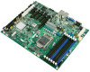
the Intel® Server Board S3420GPRX. This chapter provides a photograph of the product, list of the server board features, and diagrams showing the location of important components and connections on the server board. Figure 1. Intel® Server Board S3420GPRX Intel® Server Board S3420GPRX User Guide - Intel S3420GPRX | User Guide - Page 15
Management Module 3 Lite One PCI Express* Gen2 x16 (x8 throughput) connector. Five 4-pin fan head (four system fans and one processor fan). On-board ServerEngines* LLC Pilot II BMC Controller • Integrated 2D Video Controller • 64 MB DDR2 667 MHz Memory 2 Intel® Server Board S3420GPRX User Guide - Intel S3420GPRX | User Guide - Page 16
and beyond ATX, 12" x 9.6", 1U thermal optimized Connector and Header Locations The following figure shows the board layout of the server board. Each connector and major component is identified by a number or letter. The table provides the description. Intel® Server Board S3420GPRX User Guide 3 - Intel S3420GPRX | User Guide - Page 17
A. Dual Intel® I/O Expansion Module Connectors B. PCI Express x16 Gen2 C. CMOS Battery D. RJ-45 Serial port Connector E. RJ-45 U. PCH Chipset V. SAS Module Connector W. System FAN 1 X. IPMB Connector Y. SATA SGPIO Connector Z. HSBP Connector AA. USB Floppy 4 Intel® Server Board S3420GPRX User Guide - Intel S3420GPRX | User Guide - Page 18
Panel Connector KK. Internal Serial Port Figure 2. Server Board Connector and Component Locations Configuration Jumpers The server board has several jumper blocks that can be used to configure, protect, or recover specific features of the server board. Intel® Server Board S3420GPRX User Guide 5 - Intel S3420GPRX | User Guide - Page 19
place for normal system operation. (Default) To clear administrator and user passwords, power on server with pins 2-3 connected. The password are cleared within 5-10 seconds. These pins should (Default) Integrated BMC Firmware Force Update Mode - Enabled 6 Intel® Server Board S3420GPRX User Guide - Intel S3420GPRX | User Guide - Page 20
-45 GbE LAN Connector (NIC3 and NIC4) G. RJ-45 GbE(NIC5) and Dual USB combo connector H. RJ-45 Serial Port Figure 4. Server Board Rear I/O Layout The NIC LEDs on the NIC connector are marked as A and B. The following table provides the LED information. Intel® Server Board S3420GPRX User Guide 7 - Intel S3420GPRX | User Guide - Page 21
the BIOS Setup utility, see the Intel® Server Board S3420GPRX Technical Product Specification. For information on how to configure RAID, refer to the RAID software user's guide at: http://www.intel.com/support/motherboards/server/S3420GPRX/howto.htm Hardware Requirements To avoid integration - Intel S3420GPRX | User Guide - Page 22
supported processors, see the links under "Additional Information and Software". Memory The Intel®Server Board S3420GPRX supports a DDR3-based memory subsystem. The server board supports XX XX XX XX XXX XX XXX X X X X X X X X X X X X X Intel® Server Board S3420GPRX User Guide 9 - Intel S3420GPRX | User Guide - Page 23
to eight hard drives with an expander backplane. The optional Intel® SAS Entry RAID Module AXX4SASMOD also provides a SGPIO (Serial General Purpose Input / Output) connector and a SCSI Enclosure Services (SES) connector for backplane drive LED control. 10 Intel® Server Board S3420GPRX User Guide - Intel S3420GPRX | User Guide - Page 24
accessory. This activation key is placed on the SAS Software RAID 5 connector located on the Intel® SAS Entry RAID Module AXX4SASMOD. For installation instructions, see the documentation included with the SAS Module AXX4SASMOD and the activation key. Intel® Server Board S3420GPRX User Guide 11 - Intel S3420GPRX | User Guide - Page 25
RAID software user's guide at: http://www.intel.com/support/motherboards/server/S3420GPRX/howto.htm Intel® Remote Management Module 3 Lite The Intel® Remote Management Module 3 Lite plugs into connectors on the Intel® Server Board S3420GPRX, acting as components of the server board-not as separate - Intel S3420GPRX | User Guide - Page 26
Access Setup If you cannot access the BIOS Setup, you might need to clear the CMOS memory. For instructions on clearing the CMOS, see "Clearing the CMOS". Setup Menus Each BIOS Setup menu page for any reason, the feature's value field is inaccessible. Intel® Server Board S3420GPRX User Guide 13 - Intel S3420GPRX | User Guide - Page 27
if the key is pressed, the user is returned to where they were before was pressed without affecting any existing field values. 14 Intel® Server Board S3420GPRX User Guide - Intel S3420GPRX | User Guide - Page 28
follow a recovery process to return the system to service. Refer to "Additional Information and Software" for a link to necessary software and instructions. Recording the Current BIOS Settings 1. Boot the your computer at the end of the procedure. Intel® Server Board S3420GPRX User Guide 15 - Intel S3420GPRX | User Guide - Page 29
. Note: Before attempting a BIOS upgrade, review the instructions and release notes provided in the readme file distributed with . Note: You may encounter a CMOS Checksum error or other problem after reboot. If this happens, shut down the system and 16 Intel® Server Board S3420GPRX User Guide - Intel S3420GPRX | User Guide - Page 30
can be accomplished from SATA CD and USB Mass Storage device. Please note this platform does not support recovery from a USB floppy. The recovery media must contain the following files under the root directory: the BIOS POST during the first boot. Intel® Server Board S3420GPRX User Guide 17 - Intel S3420GPRX | User Guide - Page 31
jumper to reset the configuration RAM. The CMOS Clear jumper is located on jumper block J1F5 on the server board. 1. Power down the system and disconnect the AC power. 2. Open the server chassis. For instructions, see your server chassis documentation. 18 Intel® Server Board S3420GPRX User Guide - Intel S3420GPRX | User Guide - Page 32
five seconds. 5. Move the jumper back to default position, covering pins 1 and 2. 6. Close the server chassis. 7. Reconnect the AC power and power up the system. The CMOS is cleared and can be In the unlikely event the Integrated BMC firmware update Intel® Server Board S3420GPRX User Guide 19 - Intel S3420GPRX | User Guide - Page 33
and remove the AC power cord. 8. Open the server chassis. 9. Move jumper from the enabled position (covering pins 2 and 3) to the disabled position (covering pins 1 and 2). 10. Close the server chassis. 11. Reconnect the AC cord and power up the server. 20 Intel® Server Board S3420GPRX User Guide - Intel S3420GPRX | User Guide - Page 34
in "Safety Information". 2. Turn off all peripheral devices connected to the server. 3. Turn off the server. 4. Disconnect the AC power cord from the server. 5. Remove the server's cover and locate the DIMM sockets (see letters "A" to "E" Figure 10). Intel® Server Board S3420GPRX User Guide 21 - Intel S3420GPRX | User Guide - Page 35
Memory instructions on removing the server's cover. 6. Gently spread the retaining clips at each end of the socket. The DIMM will lift from the socket. 7. Holding the DIMM by the edges, lift it from the socket, and store it in an anti-static package. 22 Intel® Server Board S3420GPRX User Guide - Intel S3420GPRX | User Guide - Page 36
all peripheral devices connected to the server. Turn off the server. 3. Disconnect the AC power cord from the server. 4. Remove the server's cover. See the documentation that came with your server chassis for instructions on removing the server's cover. Intel® Server Board S3420GPRX User Guide 23 - Intel S3420GPRX | User Guide - Page 37
5. Locate the processor socket and open the socket lever (see Figure 11). REMOVE A B AF003186 Figure 11. Lifting the Load Lever 6. Open the load plate (see letter "A" and "B" in Figure 12). A REMOVE B REMOVE AF003187 Figure 12. Open the Load Plate 24 Intel® Server Board S3420GPRX User Guide - Intel S3420GPRX | User Guide - Page 38
out of the box and remove the protective shipping cover (Figure 14). A AF003189 Figure 14. Remove the Processor Protective Cover 9. Align the processor cutouts to match the two socket pins, and insert the processor into the socket as shown in Figure 15. Intel® Server Board S3420GPRX User Guide 25 - Intel S3420GPRX | User Guide - Page 39
engages under the socket lever when fully closed (see letter "B" and "C" in Figure 16). A B C D Figure 16. Close the Load Plate and Socket Lever AF003191 26 Intel® Server Board S3420GPRX User Guide - Intel S3420GPRX | User Guide - Page 40
the Heatsink(s) Before installing the heat sink, you must install your processor. For instructions, see "Installing the Processor" on page -23. Caution: The heat sink has Thermal Interface firmly tightened. Figure 17. Installing the Heatsink Assembly Intel® Server Board S3420GPRX User Guide 27 - Intel S3420GPRX | User Guide - Page 41
The riser card at PCI slot 6 of the board supports a low-profile, half-length PCI Express* add-in card. Refer to the SR1630GPRX/SR1630HGPRX System Service Guide for more detailed information on how to install a to remove the shield. Retain the screw. 28 Intel® Server Board S3420GPRX User Guide - Intel S3420GPRX | User Guide - Page 42
the riser card straight down into the slot. Tipping it in the slot while installing it may damage the riser card or slot on the server board. 4. Use the screw removed in Step 1 to secure the riser card assembly to the chassis. Intel® Server Board S3420GPRX User Guide 29 - Intel S3420GPRX | User Guide - Page 43
server board powers the RTC for up to 10 years in the absence of power. When the battery starts to weaken, it loses voltage, and the server settings stored in CMOS RAM in the RTC (for example, the date and time) may be wrong. Contact your customer service 30 Intel® Server Board S3420GPRX User Guide - Intel S3420GPRX | User Guide - Page 44
server. Turn off the server. 3. Disconnect the AC power cord from the server. 4. Remove the server's cover and locate the battery. See the documentation that came with your server chassis for instructions on removing the server settings to the RTC. Intel® Server Board S3420GPRX User Guide 31 - Intel S3420GPRX | User Guide - Page 45
32 Intel® Server Board S3420GPRX User Guide - Intel S3420GPRX | User Guide - Page 46
the POST code to the POST Code Diagnostic LEDs on the back edge of the server board. To assist in troubleshooting a system hang during the POST process, you can use the Diagnostic LEDs to to the diagnostic LED decoder. The LEDs are decoded as follows: Intel® Server Board S3420GPRX User Guide 33 - Intel S3420GPRX | User Guide - Page 47
cache initialization (including AP) 0x12h X X X O X X O X Starting application processor initialization 0x13h X X X O X X O O SMM initialization Chipset 0x21h X X O X X X X O Initializing a chipset component Memory 34 Intel® Server Board S3420GPRX User Guide - Intel S3420GPRX | User Guide - Page 48
X X O X X O X O Configuring memory parameters in the memory controller X X O X X O O X Optimizing memory controller settings X X O X X O O O Initializing memory, such as ECC init X X O X X X X X Testing memory Intel® Server Board S3420GPRX User Guide 35 - Intel S3420GPRX | User Guide - Page 49
bus and all devices O X O O Reserved for ATA O O X X Enable Smart if supported by ATA device O O X O Reserved for ATA O X O O X O O O O X X X Resetting the console controller O X X O Disabling the console controller 36 Intel® Server Board S3420GPRX User Guide - Intel S3420GPRX | User Guide - Page 50
O X X Clearing keyboard input buffer 0x95 O X X O X O X O Instructing keyboard to run Self Test (PS/2 only) Mouse (only USB) / Mouse (PS/2 detection, etc.) 0xBC O X O O O O X X Enabling / configuring a removable media device Intel® Server Board S3420GPRX User Guide 37 - Intel S3420GPRX | User Guide - Page 51
by a beep code) 0xE4 O O O X O X X X Entered EFI driver execution phase (DXE) 0xE5 O O O X O X X O Started dispatching drivers 0xE6 O O O X O X O X Started connecting drivers DXE Drivers (not accompanied by a beep code) 38 Intel® Server Board S3420GPRX User Guide - Intel S3420GPRX | User Guide - Page 52
memory mode. 0xF4 O O O O X O X X Entering Sleep state 0xF5 O O O O X O X O Exiting Sleep state 0xF8 O O O O O X X X Operating system has requested EFI to close boot services O O O O Unable to complete crisis recovery Intel® Server Board S3420GPRX User Guide 39 - Intel S3420GPRX | User Guide - Page 53
O O X O X O O Memory Test Error: Memory failed Hardware BIST. O O O X O O X O Population Error: RDIMMs and UDIMMs cannot be mixed in the system. O O O X O O O X Mismatch Error: More than two Quad-Ranked DIMMS in a channel. 40 Intel® Server Board S3420GPRX User Guide - Intel S3420GPRX | User Guide - Page 54
out this form completely is required for any escalation Customer Contact Information: Customer Support Case Intel® Server Board or System: (Example: S3420GPRX or SR1630GPRX/SR1630HGPRX Server Chassis: (Example: SR1630GPRX/SR1630HGPRX. If third-party chassis used, indicate make and model - Intel S3420GPRX | User Guide - Page 55
: Processor 1 Processor 2 Processor 3 Processor 4 Type Speed sSpec Thermal Solution Thermal solution (Heatsink) examples: (1U, Passive w/air ducting, Active w/fan, etc Memory: Manufacturer Part Number DRAM Part Number On Intel tested list? 42 Intel® Server Board S3420GPRX User Guide - Intel S3420GPRX | User Guide - Page 56
Information (Example: RedHat* Enterprise Linux, Microsoft* Windows* Server 2003, Service pack 1, OEM CD): Manufacturer: Version: Language version (English, Arabic, Chinese (Simplified)): Service Pack Level or Kernel Revision: Distribution (OEM/Retail Intel® Server Board S3420GPRX User Guide 43 - Intel S3420GPRX | User Guide - Page 57
latest RAID driver been tried? (Yes/No): RAID volumes configuration (disks & RAID level): RAID volume use (Boot device/Data Volume): Is BBU (Battery Backup Unit) installed? (Yes/No): BBU part number Detailed description of issue: Troubleshooting tried: 44 Intel® Server Board S3420GPRX User Guide - Intel S3420GPRX | User Guide - Page 58
Steps to replicate the issue: Issue impact statements: Do you have any potential Intel system, or component purchases that this issue is holding up? If yes, description below. *All other brands and names are property of their respective owners. Intel® Server Board S3420GPRX User Guide 45 - Intel S3420GPRX | User Guide - Page 59
46 Intel® Server Board S3420GPRX User Guide - Intel S3420GPRX | User Guide - Page 60
www.intel.com/reseller/. Note: You will need to log in to the Reseller site to obtain the 24x7 number. Warranty Information To obtain warranty information, visit the following Intel web site: http://www.intel.com/support/motherboards/server/sb/CS-010807.htm Intel® Server Board S3420GPRX User Guide - Intel S3420GPRX | User Guide - Page 61
48 Intel® Server Board S3420GPRX User Guide - Intel S3420GPRX | User Guide - Page 62
Intel® Server Board S3420GPRX been has been tested and verified to comply with the following electromagnetic compatibility (EMC) regulations when installed a compatible Intel® host system. For information on compatible host system(s) see Intel's Server ) Intel® Server Board S3420GPRX User Guide 49 - Intel S3420GPRX | User Guide - Page 63
Regulatory Compliance UL Mark Region USA/Canada Marking CE Mark Europe EMC Marking (Class A) Canada BSMI Marking (Class A) Taiwan CANADA ICES-003 CLASS A D33025 50 Intel® Server Board S3420GPRX User Guide - Intel S3420GPRX | User Guide - Page 64
for additional information. Recycling Package Mark Other than China RoHS China Electromagnetic Compatibility Notices FCC (USA) This device complies with Part 15 of the interference received, including interference that may cause undesired operation. Intel® Server Board S3420GPRX User Guide 51 - Intel S3420GPRX | User Guide - Page 65
the EMC performance of this product, contact: Intel Corporation 5200 N.E. Elam Young Parkway Hillsboro, OR , if not installed and used in accordance with the instructions, may cause harmful interference to radio communications. However, Communications. 52 Intel® Server Board S3420GPRX User Guide - Intel S3420GPRX | User Guide - Page 66
. Obtain certificate from local Intel representative 3. Name of Certification Recipient: Intel Corporation 4. Date of Manufacturer: Refer to date code on product 5. Manufacturer/Nation: Intel Corporation/Refer to country of origin marked on product Intel® Server Board S3420GPRX User Guide 53 - Intel S3420GPRX | User Guide - Page 67
-back systems and requirements vary by country. Contact the retailer or distributor of this product for information about product recycling and / or take-back. 54 Intel® Server Board S3420GPRX User Guide - Intel S3420GPRX | User Guide - Page 68
, and reload the operating system Cold boot reset. Turn the system power off and then on. This clears system memory, restarts POST, reloads the operating system, and halts power to all peripherals Press Reset button Power off/on button Intel® Server Board S3420GPRX User Guide 55 - Intel S3420GPRX | User Guide - Page 69
• Are all integrated components from the tested components lists? Check the tested memory, and chassis lists, as well as the supported hardware and operating system list. See "Additional Information and Software" for links to the tested component lists. 56 Intel® Server Board S3420GPRX User Guide - Intel S3420GPRX | User Guide - Page 70
Diagnostic Testing This section provides a more detailed approach to identifying a hardware problem and locating its source. Caution: Turn off devices before disconnecting cables: system prompt does not display, see "No Characters Display on Screen". Intel® Server Board S3420GPRX User Guide 57 - Intel S3420GPRX | User Guide - Page 71
according to the system requirements. • Remove the processor(s) and re-seat them. • Make sure the chassis standoffs are installed only below mounting holes. Misplaced standoffs can contact the pins on the bottom of the server board and cause a short. 58 Intel® Server Board S3420GPRX User Guide - Intel S3420GPRX | User Guide - Page 72
memory DIMMs comply with the system requirements. • Make sure the memory DIMMs were populated according to the system requirements. • Remove the memory DIMMs and re-seat them. • Make sure the processor . Contact your service representative or authorized Intel® Server Board S3420GPRX User Guide 59 - Intel S3420GPRX | User Guide - Page 73
-ROM drive's power and signal cables properly installed? • Are all relevant switches and jumpers on the drive set correctly? • Is the drive properly configured? 60 Intel® Server Board S3420GPRX User Guide - Intel S3420GPRX | User Guide - Page 74
working when an add-in adapter was installed • Make sure the cable is connected to the port from the on-board network controller. • Make sure your BIOS is current. Refer to the "Additional Information and Software" for a link to the current version. Intel® Server Board S3420GPRX User Guide 61 - Intel S3420GPRX | User Guide - Page 75
do not work. • If you are running the software from a floppy disk, CD-ROM or DVD-ROM, try a different disk. • Make sure the correct device drivers installed. If the problems persist, contact the software vendor's customer service representative. 62 Intel® Server Board S3420GPRX User Guide - Intel S3420GPRX | User Guide - Page 76
each SCSI ID number is unique on the SCSI bus. Refer to your drive documentation for details on setting the SCSI ID for your drives. Intel® Server Board S3420GPRX User Guide 63 - Intel S3420GPRX | User Guide - Page 77
-ROM to be the first bootable device. LED Information The Intel® Server Board S3420GP includes LEDs that can aid in troubleshooting your system. The following table lists these LEDs and provides = Power on or S0) • Slow Blink = Low power state (S1 - S3) 64 Intel® Server Board S3420GPRX User Guide - Intel S3420GPRX | User Guide - Page 78
Beeps 3 Reason for Beeps and Action to Take System halted because a fatal error related to the memory was detected. In the case of POST error(s) that are listed as Major, the BIOS enters the system without user intervention. The default is disabled. Intel® Server Board S3420GPRX User Guide 65
-
 1
1 -
 2
2 -
 3
3 -
 4
4 -
 5
5 -
 6
6 -
 7
7 -
8
-
9
-
10
-
11
-
12
-
13
-
14
-
15
-
16
-
17
-
18
-
19
-
20
-
21
-
22
-
23
-
24
-
25
-
26
-
27
-
28
-
29
-
30
-
31
-
32
-
33
-
34
-
35
-
36
-
37
-
38
-
39
-
40
-
41
-
42
-
43
-
44
-
45
-
46
-
47
-
48
-
49
-
50
-
51
-
52
-
53
-
54
-
55
-
56
-
57
-
58
-
59
-
60
-
61
-
62
-
63
-
64
-
65
-
66
-
67
-
68
-
69
-
70
-
71
-
72
-
73
-
74
-
75
-
76
-
77
-
78
 |
 |

Intel
®
Server Board S3420GPRX User
Guide
A Guide for Technically Qualified Assemblers of Intel® Identified Subassemblies/Products
Intel Order Number E90566-002