Intel S5000PSLSATAR Product Specification
Intel S5000PSLSATAR - Inte Dual LGA771 Manual
 |
UPC - 735858196062
View all Intel S5000PSLSATAR manuals
Add to My Manuals
Save this manual to your list of manuals |
Intel S5000PSLSATAR manual content summary:
- Intel S5000PSLSATAR | Product Specification - Page 1
Intel® Server Board S5000PAL / S5000XAL Technical Product Specification Intel order number: D31979-010 Revision 1.9 March 2009 Enterprise Platforms and Services Division - Marketing ii Revision 1.9 Intel order number: D31979-010 - Intel S5000PSLSATAR | Product Specification - Page 2
First external release. Updated theoretical memory bandwidth performance numbers. Added Platform Control sections. Memory RAS is now available. Updated the Intel® S5000 Server Board Family Datasheet. Updated processor support section. Updated Table 44 BMC sensor. Updated Processor support - Intel S5000PSLSATAR | Product Specification - Page 3
Intel® Server Board S5000PAL and the Intel® Server Board S5000XAL may contain design defects or errors known as errata which may cause the product to deviate from published specifications. Current characterized errata are available on request. Intel Corporation server baseboards support peripheral - Intel S5000PSLSATAR | Product Specification - Page 4
Light Guided Diagnostic LED Locations 17 2.2.3 External I/O Connector Locations 18 2.2.4 Server Board Mechanical Drawings 19 3. Functional Architecture ...24 3.1 Intel® 5000P and 5000X Memory Controller Hubs (MCH 25 3.1.1 System Bus Interface 25 3.1.2 Processor Support 25 3.1.3 Memory - Intel S5000PSLSATAR | Product Specification - Page 5
Fault LEDs 67 7.4 Processor Fault LED 67 7.5 Post Code Diagnostic LEDs 68 8. Power and Environmental Specifications 69 8.1 Intel® Server Board S5000PAL / S5000XAL Design Specifications 69 8.2 Server Board Power Requirements 70 8.2.1 Processor Power Support 70 8.2.2 Power Supply - Intel S5000PSLSATAR | Product Specification - Page 6
Intel® Server Board S5000PAL / S5000XAL TPS 9.2 Electromagnetic Compatibility Notices 79 9.2.1 FCC Verification Statement (USA 79 9.2.2 ICES-003 (Canada 79 9.2.3 POST Code Diagnostic LED Decoder 100 Appendix D: POST Error Messages and Handling 104 Appendix E: Supported Intel® Server Chassis - Intel S5000PSLSATAR | Product Specification - Page 7
21 Figure 7. Intel® Server Board S5000PAL / S5000XAL - Restricted Areas on Side 2 22 Figure 8. Intel® Server Board S5000PAL / S5000XAL - Primary Side Duct and VR Restrictions23 Figure 9. Server Board Functional Block Diagram 24 Figure 10. CEK Processor Mounting 26 Figure 11. Memory Layout ...27 - Intel S5000PSLSATAR | Product Specification - Page 8
Connector Pin-out (J9K1,J5K1,J3K1,J3K2,J7A2,J7A1 59 Table 32. Recovery Jumpers (J1D1, J1D2, J1D3 60 Table 33: Server Board Design Specifications 69 Table 34. Dual-Core Intel® Xeon® Processor 5000 Sequence TDP Guidelines per processor .. 70 Table 35. 600W Load Ratings ...71 Revision 1.9 ix - Intel S5000PSLSATAR | Product Specification - Page 9
List of Tables Intel® Server Board S5000PAL / S5000XAL TPS Table 36: No load operating range 71 ...76 Table 43. BMC Sensors...86 Table 44: POST Progress Code LED Example 100 Table 45. Diagnostic LED POST Code Decoder 101 Table 46. POST Error Messages and Handling 104 Table 47. POST - Intel S5000PSLSATAR | Product Specification - Page 10
Intel® Server Board S5000PAL / S5000XAL TPS < This page intentionally left blank. > List of Tables Revision 1.9 xi Intel order number: D31979-010 - Intel S5000PSLSATAR | Product Specification - Page 11
Specifications • Chapter 9 - Regulatory and Certification Information • Appendix A - Integration and Usage Tips • Appendix B - BMC Sensor Tables • Appendix C - POST Code Diagnostic LED Decoder • Appendix D - Post Code Errors • Appendix E - Supported Intel® Server Chassis 1.2 Server Board - Intel S5000PSLSATAR | Product Specification - Page 12
On-board Hard Drive Controller LAN System Fans System Management Description 771-pin LGA sockets supporting 1 or 2 Dual-Core Intel® Xeon® processors 5000 sequence, with system bus speeds of 667 MHz, 1066 MHz, or 1333 MHz 8 Keyed DIMM slots supporting fully buffered DIMM technology (FBDIMM) memory - Intel S5000PSLSATAR | Product Specification - Page 13
Product Overview 2.2 Server Board Layout Intel® Server Board S5000PAL / S5000XAL TPS 14 Revision 1.9 Intel order number: D31979-010 - Intel S5000PSLSATAR | Product Specification - Page 14
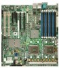
Intel® Server Board S5000PAL / S5000XAL TPS Product Overview 2.2.1 Connector and Component Locations The following figure shows the board layout of the server board. Each connector and major component is identified by a number or letter, and a description is given below the figure. A B C D EF - Intel S5000PSLSATAR | Product Specification - Page 15
W CPU Power Connector X Main Power Connector Y Battery Z Power Supply Management Connector AA Dual Port USB 2.0 Header BB System Fan #1 Header CC SSI 24-pin Control Panel Header DD SATA 0 EE SATA 1 FF SATA 2 GG SATA 3 HH SATA 4 II SATA 5 JJ SATA SW RAID 5 Activation Key Connector KK Intel® Remote - Intel S5000PSLSATAR | Product Specification - Page 16
Intel® Server Board S5000PAL / S5000XAL TPS Product Overview 2.2.2 Light Guided Diagnostic LED Locations A B C I J K LDM N O P GS QE RF TP02317 Description A Post Code Diagnostic LEDs Description E CPU Fault LED B System Identification LED - Blue F CPU Fault LED C System Status LED - - Intel S5000PSLSATAR | Product Specification - Page 17
I/O components for the server board. A B C D A PS/2 Mouse B PS/2 Keyboard C Serial Port B D NIC port 1 (1 Gb) E F GH TP02296 E NIC port 2 (1 Gb) F Video G USB port 1 H USB port 2 Figure 3. Intel® Server Board S5000PAL / S5000XAL ATX I/O Layout 18 Revision 1.9 Intel order number: D31979 - Intel S5000PSLSATAR | Product Specification - Page 18
] AMP 794108-1 6012A0022801 2 x 59.69 [2.350] Molex 3930-0080 6012A0022801 124.46 [4.900] 2 x 141.25 [5.561] 2 x 223.80 [8.811] 2 x 281.94 [11.100] TP02316 Figure 4. Intel® Server Board S5000PAL / S5000XAL - Hole and Component Positions (1 of 2) Revision 1.9 19 - Intel S5000PSLSATAR | Product Specification - Page 19
Product Overview Intel® Server Board S5000PAL / S5000XAL TPS 16.51 [0.650] 3 x 13.59 [0.535] 2 x 12.33 [0.485] 12.27 [0.483] 9.07 .31 [3.280] 96.25 [3.789] 104.39 [4.110] 280.21 [11.032] TP02292 Figure 5. Intel® Server Board S5000PAL / S5000XAL - Hole and Component Positions (2 of 2) 20 Revision - Intel S5000PSLSATAR | Product Specification - Page 20
.84 [4.403] 120.93 [4.761] 199.67 [7.861] 203.48 [8.011] 282.22 [11.111] REF ONLY H < 11 mm [0.433"] Under Heat Sink TP02293 Figure 6. Intel® Server Board S5000PAL / S5000XAL - Restricted Areas on Side 1 Revision 1.9 21 Intel order number: D31979-010 - Intel S5000PSLSATAR | Product Specification - Page 21
"] on Side 2 320.04 [12.600] Ø 29.46 [1.160] Typ. Backside Spring Area. No Motherboard Component Placement Allowed. 180.34 [7.100] 200.03 [7.875] 0.200" [5.08 mm Max] Figure 7. Intel® Server Board S5000PAL / S5000XAL - Restricted Areas on Side 2 22 Revision 1.9 Intel order number: D31979-010 - Intel S5000PSLSATAR | Product Specification - Page 22
Intel® Server Board S5000PAL / S5000XAL TPS Product Overview 16.51 [0.650] 0.00 [0.000] 113.13 [4.454 "] Under VR 256.54 [10.100] NO Components Allowed H < 27 mm [1.063"] Under Duct TP02295 Figure 8. Intel® Server Board S5000PAL / S5000XAL - Primary Side Duct and VR Restrictions Revision 1.9 23 - Intel S5000PSLSATAR | Product Specification - Page 23
the Intel® Server Board S5000PAL / S5000XAL is based on the Intel® 5000 Chipset Family. The chipset is designed for systems based on the Dual-Core Intel® Xeon® processor 5000 sequence with system bus speeds of 667 MHz, 1066 MHz, and 1333 MHz. The chipset is made up of two main components: the Memory - Intel S5000PSLSATAR | Product Specification - Page 24
.intel.com/support/motherboards/server/sb/CS-022346.htm/ is sub-directory of above S5000PAL URL that reflects supported processor list) Note: Only Dual-Core Intel® Xeon® processors 5000 sequence, that support system bus speeds of 667 MHz, 1066 MHz, and1333 MHz are supported on this server board - Intel S5000PSLSATAR | Product Specification - Page 25
material (TIM) Server board CEK spring Chassis Figure 10. CEK Processor Mounting 3.1.3 Memory Sub-system On the Intel® Server Board S5000PAL / S5000XAL, the MCH provides four channels of Fully Buffered DIMM (FB-DIMM) memory. Each channel can support up to 2 Dual Ranked FB-DIMM DDR2 DIMMs. FBDIMM - Intel S5000PSLSATAR | Product Specification - Page 26
and 21.0 GB/s for 667. On the Intel® Server Board S5000PAL / S5000XAL, a pair of channels becomes a branch where Branch 0 consists of channels A and B, and Branch 1 consists of channels C and D. FBD memory channels are organized into two branches for support of RAID 1(mirroring). Channel B Channel - Intel S5000PSLSATAR | Product Specification - Page 27
Dual Rank 256 Mb 512 Mb 1024 Mb 2048 Mb Maximum Capacity Mirrored Mode 4 GB 8 GB 16 GB 16 GB Maximum Capacity Non-Mirrored Mode 8 GB 16 GB 32 GB 32 GB Note: DDR2 DIMMs that are not fully buffered are NOT supported on this server board. See the Intel® Server Board S5000PAL / S5000XAL Tested Memory - Intel S5000PSLSATAR | Product Specification - Page 28
Intel® Server Board S5000PAL / S5000XAL TPS Functional Architecture Y (0) Y Y (0) Y Y (0, 1) Notes: - Single channel mode is only tested and supported with a 512MB x8 FBDIMM installed in DIMM Slot A1. - The supported memory configurations must meet population rules defined above. - For best - Intel S5000PSLSATAR | Product Specification - Page 29
Architecture Intel® Server Board S5000PAL / S5000XAL TPS 3.1.3.4 Non-mirrored mode memory upgrades The minimum memory upgrade a replicate copy of the data in branch 0. The minimum DIMM configuration to support memory mirroring is four DIMMs, populated as shown in Figure 13 above. All four - Intel S5000PSLSATAR | Product Specification - Page 30
Intel® Server Board S5000PAL / S5000XAL TPS Functional Architecture 3.1.3.4.2 DIMM Sparing Mode Memory Configuration The MCH sparing occurs within a given bank of memory and is not supported across branches. There are two supported Memory Sparing configurations. 3.1.3.4.2.1 Single Branch Mode - Intel S5000PSLSATAR | Product Specification - Page 31
, size and speed. • Sparing should be enabled in BIOS setup. • BIOS will configure Rank Sparing Mode. • The larger of the compatible I/O devices and features. The server board uses the following ESB-2 features: • PCI-X* bus interface • Six Channel SATA interface w/SATA Busy LED Control • Dual - Intel S5000PSLSATAR | Product Specification - Page 32
most of the listed features as they pertain to this server board. For more detail information, see the Intel® S5000 Series Chipsets Server Board Family Datasheet or the Intel® Enterprise South Bridge-2 External Design Specification (Yellow Cover) 3.2.1 PCI Sub-system The primary I/O buses for the - Intel S5000PSLSATAR | Product Specification - Page 33
Functional Architecture Intel® Server Board S5000PAL / S5000XAL TPS 3.2.1.5 PE4, PE5: Two x4 PCI Express* Bus Segments Two x4 PCI Express* bus segments are directed through the MCH. These PCI Express segments, PE4 and PE5, support one x8 or two x4 PCI Express segments to the low profile riser - Intel S5000PSLSATAR | Product Specification - Page 34
SATA ports on the server board are numbered SATA-0 thru SATA-5. The SATA ports can be enabled/disabled and/or configured by accessing the BIOS Setup Utility during POST. 3.2.2.1 Intel® Embedded Server RAID Technology II Support The onboard storage capability of this server board includes support - Intel S5000PSLSATAR | Product Specification - Page 35
Functional Architecture Intel® Server Board S5000PAL / S5000XAL TPS 3.2.2.2 Intel® Embedded Server RAID Technology Option ROM The Intel® Embedded Server RAID Technology for SATA Option ROM provides a pre-OS user interface for the Intel® Embedded Server RAID Technology implementation and provides - Intel S5000PSLSATAR | Product Specification - Page 36
. Requests are serviced in a manner that ensures display integrity and maximum CPU/co-processor drawing performance. The server board supports a 16MB (4Meg x 16-bit x 4 banks) DDR SDRAM device for video memory. 3.3.1.3 Dual Video The BIOS supports single and dual video modes. The dual video mode - Intel S5000PSLSATAR | Product Specification - Page 37
Intel® Server Board S5000PAL / S5000XAL TPS 3.4 Network Interface Controller (NIC) Network interface support is provided from the built in Dual GbE MAC features of the ESB-2 in conjunction with the Intel® 82563EB compact Physical Layer Transceiver (PHY). Together, they provide the server board - Intel S5000PSLSATAR | Product Specification - Page 38
Intel® Server Board S5000PAL / S5000XAL TPS Functional Architecture 3.5 Super I/O Legacy I/O support is provided by using a National Semiconductor* PC87427 Super I/O device. This chip contains all of the necessary circuitry to support the following functions: • GPIOs • Two serial ports • Keyboard - Intel S5000PSLSATAR | Product Specification - Page 39
floppy devices. 3.5.1.3 Keyboard and Mouse Support Dual stacked PS/2 ports, located on the back edge of the server board, are provided for keyboard and mouse support. Either port can support a mouse or keyboard. Neither port supports hot plugging. 40 Revision 1.9 Intel order number: D31979-010 - Intel S5000PSLSATAR | Product Specification - Page 40
Intel® Server Board S5000PAL / S5000XAL TPS Functional Architecture 3.5.1.4 Wake-up Control The super I/O contains functionality that allows various events to power-on and power-off the system. 3.5.1.5 System Health Support The super I/O provides an interface via GPIOs for BIOS and Server - Intel S5000PSLSATAR | Product Specification - Page 41
Platform Management Intel® Server Board S5000PAL / S5000XAL TPS 4. Platform Management The platform management sub-system on the server board is based on the integrated Baseboard Management Controller (BMC) features of the ESB-2. The on board platform management subsystem consists of - Intel S5000PSLSATAR | Product Specification - Page 42
designators printed on the silkscreen. Table 9. Board Connector Matrix Connector Quantity Reference Designators Power supply CPU Main Memory Full Height Riser Low Profile Riser Bridge Board Connector RMM RMM NIC Intel® I/O Expansion Module SATA RAID Key IDE (I/O + Power) 3 J3K4 J3K3 J1K1 - Intel S5000PSLSATAR | Product Specification - Page 43
Connector / Header Locations and Pin-outs Intel® Server Board S5000PAL / S5000XAL TPS Connector System Recovery Setting Jumpers power related connectors; one SSI compliant 2x4 pin power connector (J3K4) providing support for additional 12V, and one SSI compliant 1x5 pin connector (J1K1) providing - Intel S5000PSLSATAR | Product Specification - Page 44
server board for sole support of the optional Intel® Remote Management Module. There is no support for third party ASMI cards on this server board. Note: This connector is NOT compatible for use with Intel® Server Management Module Professional Edition (Product Code AXXIMMPRO) or the Intel® Server - Intel S5000PSLSATAR | Product Specification - Page 45
Connector / Header Locations and Pin-outs Intel® Server Board S5000PAL / S5000XAL TPS Pin Signal Name Pin Signal Name 117 MII_RXCLK 118 MII_RXER_RMIIA_TXER 119 MII_RXDV_RMIIA_CRS 120 GND 5.3.2 Intel® RMM NIC Connector The server board provides an internal 30-pin mezzanine style connector - Intel S5000PSLSATAR | Product Specification - Page 46
server board has two riser card slots. The full height riser slot (J4F1) utilizes Intel® Adaptive Slot Technology. It is capable of supporting riser cards that support GND 17 18 GND 19 PE4_MCH_TXP_C Pin Side A 1 PCI Spec Signal 2 P12V 3 P12V 4 GND 5 PD_LP_TCK 6 PU_LP_TDI - Intel S5000PSLSATAR | Product Specification - Page 47
Connector / Header Locations and Pin-outs Intel® Server Board S5000PAL / S5000XAL TPS Pin Side B PCI Spec Signal 20 PE4_MCH_TXN_C 21 GND 22 GND 23 PE4_MCH_TXP_C 24 PE4_MCH_TXN_C 25 GND 26 GND 27 PE4_MCH_TXP_C 28 PE4_MCH_TXN_C 29 GND 30 P3V3 31 - Intel S5000PSLSATAR | Product Specification - Page 48
Intel® Server Board S5000PAL / S5000XAL TPS Connector / Header Locations and Pin-outs Pin-Side B PCI Spec Signal Pin-Side A PCI Spec Signal 128 GND 128 HSIp(0) 127 GND 127 HSIn(0) 126 HSOp(1) 126 GND 125 HSOn(1) 125 GND 124 GND 124 HSIp(1) 123 GND 123 HSIn(1) - Intel S5000PSLSATAR | Product Specification - Page 49
Connector / Header Locations and Pin-outs Intel® Server Board S5000PAL / S5000XAL TPS Pin-Side B PCI Spec Signal Pin-Side A PCI Spec Signal KEY KEY 82 Reserved 82 +5V 81 GND 81 Reserved 80 CLK1 80 GND 79 Ground 79 GNT2# 78 REQ1# 78 +3.3V 77 +3.3V - Intel S5000PSLSATAR | Product Specification - Page 50
Intel® Server Board S5000PAL / S5000XAL TPS Connector / Header Locations and Pin-outs Pin-Side B PCI Spec Signal Pin-Side A PCI Spec Signal 36 35 34 33 32 31 30 29 28 27 26 25 ] AD[38] Ground AD[36] AD[34] Ground AD[32] PXH_RST_N Ground PXH_PWROK Revision 1.9 51 Intel order number: D31979-010 - Intel S5000PSLSATAR | Product Specification - Page 51
FP_STATUS_LED2_R LAN_ACT_A_L LAN_LINKA_L PS_I2C_3VSB_SDA PS_I2C_3VSB_SCL FP_CHASSIS_INTRU LAN_ACT_B_L LAN_LINKB_L 5.6 Bridge Board Connector For use in supported Intel® Server Chassis, the server board provides a 120-pin high-density bridge board connector (J4G1) to route control panel, mid-plane - Intel S5000PSLSATAR | Product Specification - Page 52
Intel® Server Board S5000PAL / S5000XAL TPS Connector / Header Locations and Pin-outs Pin A19 A20 A21 A22 A23 A24 A25 A26 GND LED_FAN10_FAULT LED_FAN5_FAULT LED_FAN4_FAULT FAN_IO_PWM GND PCI_FAN_TACH10 FAN_TACH8 FAN_TACH6 FAN_TACH4_H7 FAN_TACH2_H7 Revision 1.9 53 Intel order number: D31979-010 - Intel S5000PSLSATAR | Product Specification - Page 53
Connector / Header Locations and Pin-outs Intel® Server Board S5000PAL / S5000XAL TPS 5.7 I/O Connector Pin-out Definition 5.7.1 VGA Connector The following table details the pin-out definition of the VGA connector (J6A1). Pin 1 2 3 4 5 6 7 8 9 10 11 - Intel S5000PSLSATAR | Product Specification - Page 54
are three planned IO modules for use on this server board: external 4 port SAS, dual Gb NIC, and Infiniband*. For more detail on the supported IO modules, please refer to the Intel® Server Board S5000PAL / S5000XAL IO Module Hardware Specification. The following table details the pin-out of the - Intel S5000PSLSATAR | Product Specification - Page 55
and Pin-outs Intel® Server Board S5000PAL / S5000XAL TPS Table 24. 50-pin Intel® I/O Expansion SATA Connectors The server board provides six SATA (Serial ATA) connectors: SATA-0 (J1H1), SATA-1 (J1G2), SATA-2 (J1G1), SATA-3 (J1F2), SATA-4 (J1F1), and SATA-5 (J1E3), for use with an internal SATA - Intel S5000PSLSATAR | Product Specification - Page 56
Intel® Server Board S5000PAL / S5000XAL TPS Connector / Header Locations and Pin-outs 5.7.6 Serial Port Connectors The server board provides one external PS/2 ports (J9A1) are provided to support both a keyboard and a mouse. Either PS/2 port can support a mouse or keyboard. The following table - Intel S5000PSLSATAR | Product Specification - Page 57
16 17 Signal Name P5V_KB_F MS_CLK_F TP_PS2_12 GND GND GND GND GND Intel® Server Board S5000PAL / S5000XAL TPS Description Keyboard / mouse power Mouse Clock Test with DATAL0) Ground One 2x5 header on the server board (J1J1) provides an option to support an additional two USB 2.0 ports. The pin- - Intel S5000PSLSATAR | Product Specification - Page 58
Intel® Server Board S5000PAL / S5000XAL TPS Connector / Header Locations and Pin-outs 5.8 Fan Headers The server board incorporates three system fan circuits which support a total of six SSI compliant 4-pin fan connectors. Two fan connectors are designated as processor cooling fans, CPU1 Fan (J9K1 - Intel S5000PSLSATAR | Product Specification - Page 59
Jumper Block Settings Intel® Server Board S5000PAL / S5000XAL TPS 6. Jumper Block Settings The server board has several 2-pin and 3-pin jumper blocks that can be used to configure, protect, or recover specific features of the server board. Pin 1 on each jumper block is denoted by an "*" or "▼". - Intel S5000PSLSATAR | Product Specification - Page 60
Intel® Server Board S5000PAL / S5000XAL TPS Jumper Block Settings 6.1.1 CMOS Clear and Password Reset The usage procedure for these two features has changed from previous generation Intel® Server Boards. The following procedure outlines the new usage model. CMOS Clear Procedure: 1. Power - Intel S5000PSLSATAR | Product Specification - Page 61
Jumper Block Settings Intel® Server Board S5000PAL / S5000XAL TPS Note: Normal BMC functionality is disabled with the force BMC update jumper set to the "enabled" position. The server should never be run with the BMC force update jumper set in this position and should only be used when the - Intel S5000PSLSATAR | Product Specification - Page 62
Intel® Server Board S5000PAL / S5000XAL TPS Jumper Block Settings 6.3 External RJ45 Serial Port Jumper Block The jumper block J8A3 1-2: DCD to DTR 3-4: DSR to DTR (factory default) TP02303 Figure 19. External RJ45 Serial Port Configuration Jumper Revision 1.9 63 Intel order number: D31979-010 - Intel S5000PSLSATAR | Product Specification - Page 63
Light Guided Diagnostics Intel® Server Board S5000PAL / S5000XAL TPS 7. Light Guided Diagnostics The server board has several on-board diagnostic LEDs to assist in troubleshooting board level issues. This section shows where each LED is located and provides a high level usage description. For a - Intel S5000PSLSATAR | Product Specification - Page 64
Intel® Server Board S5000PAL / S5000XAL TPS Light Guided Diagnostics 7.2 System ID LED and System Status LED The server board provides LEDs for both System ID and System Status. ID LED Status LED TP02309 Figure 21. System ID LED and System Status LED Locations. The - Intel S5000PSLSATAR | Product Specification - Page 65
Light Guided Diagnostics Intel® Server Board S5000PAL / S5000XAL TPS The bi-color System Status present, no good memory present • Run-time memory uncorrectable error in non-redundant mode • IERR signal asserted • Processor 1 missing • Temperature (CPU ThermTrip, memory TempHi, critical threshold - Intel S5000PSLSATAR | Product Specification - Page 66
Server Board S5000PAL / S5000XAL TPS Light Guided Diagnostics 7.3 DIMM Fault LEDs The server board provides a memory fault LED for each DIMM slot. The DIMM fault LED is illuminated when the system BIOS disables the specified DIMM after it reaches a specified number of given failures or if specific - Intel S5000PSLSATAR | Product Specification - Page 67
Light Guided Diagnostics Intel® Server Board S5000PAL / S5000XAL TPS 7.5 Post Code Diagnostic LEDs During the system boot process, BIOS executes a number of platform configuration processes, each of which is assigned a specific hex POST code number. As each configuration routine is started, BIOS - Intel S5000PSLSATAR | Product Specification - Page 68
Specifications 8. Power and Environmental Specifications 8.1 Intel® Server Board S5000PAL / S5000XAL Design Specifications Operation of the server board the Dual-Core Intel® Xeon® processor 5000 sequence maximum case temperature. Disclaimer Note: Intel Corporation server boards support add-in - Intel S5000PSLSATAR | Product Specification - Page 69
distribution implemented on this server board. Figure 25. Power Distribution Block Diagram 8.2.1 Processor Power Support The server board supports the Thermal Design Point (TDP) guideline for Dual-Core Intel® Xeon® processors 5000 sequence. The Flexible Motherboard Guidelines (FMB) has also - Intel S5000PSLSATAR | Product Specification - Page 70
Intel® Server Board S5000PAL / S5000XAL TPS Power and Environmental Specifications 8.2.2 Power Supply Output Requirements This section is for reference purposes only. Its intent is to provide guidance to system designers for determining a proper power supply for use with this server board supported - Intel S5000PSLSATAR | Product Specification - Page 71
Power and Environmental Specifications Intel® Server Board S5000PAL / S5000XAL TPS 8.2.4 Grounding The grounds less than 5 mA to prevent voltage sensing errors. The power supply must operate within specification over the full range of voltage drops from the power supply's output connector to the - Intel S5000PSLSATAR | Product Specification - Page 72
Intel® Server Board S5000PAL / S5000XAL TPS Power and Environmental Specifications 8.2.8 Dynamic Loading The output at duty cycles ranging from 10%-90%. The load transient repetition rate is only a test specification. The Δ step load may occur anywhere within the MIN load to the MAX load - Intel S5000PSLSATAR | Product Specification - Page 73
Power and Environmental Specifications Intel® Server Board S5000PAL / S5000XAL TPS 8.2.12 Ripple / Noise The maximum allowed ripple/noise output of the power supply is AC input with PSON held low, and the PSON signal with the AC input applied. 74 Revision 1.9 Intel order number: D31979-010 - Intel S5000PSLSATAR | Product Specification - Page 74
Intel® Server Board S5000PAL / S5000XAL TPS Power and Environmental Specifications Table 41. Output Voltage Timing Item Description MIN Tvout_rise Tvout_on V3 V4 Tvout_rise Tvout_on Tvout_off Figure 26. Output Voltage Timing TP02313 Revision 1.9 75 Intel order number: D31979-010 - Intel S5000PSLSATAR | Product Specification - Page 75
Power and Environmental Specifications Intel® Server Board S5000PAL / S5000XAL TPS Item Tsb_on_delay Tac_on_delay Tvout_holdup Tpwok_holdup Tpson_on_delay Tpson_pwok Tpwok_on Tpwok_off Tpwok_low Tsb_vout T5VSB_holdup Table 42. Turn On/Off Timing Description Delay from AC - Intel S5000PSLSATAR | Product Specification - Page 76
Intel® Server Board S5000PAL / S5000XAL TPS Power and Environmental Specifications 8.2.15 Residual Voltage Immunity in Standby Mode The power supply shall be immune to any residual mV when AC voltage is applied and the PSON# signal is de-asserted. Revision 1.9 77 Intel order number: D31979-010 - Intel S5000PSLSATAR | Product Specification - Page 77
Regulatory and Certification Information Intel® Server Board S5000PAL / S5000XAL TPS 9. Regulatory and Certification EMC) & 1997-42 (EMI) BSMI CNS13438 CANADA ICES-003 CLASS A CANADA NMB-003 CLASSE A None Required CPU-Model Name (A) D33025 78 Revision 1.9 Intel order number: D31979-010 - Intel S5000PSLSATAR | Product Specification - Page 78
Intel® Server Board S5000PAL / S5000XAL TPS Regulatory and Certification Information 9.2 Electromagnetic Compatibility Notices 9.2.1 FCC Verification Statement , if not installed and used in accordance with the instructions, may cause harmful interference to radio communications. However, there - Intel S5000PSLSATAR | Product Specification - Page 79
Regulatory and Certification Information Intel® Server Board S5000PAL / S5000XAL TPS 9.2.4 BSMI (Taiwan) The BSMI Certification Marking and EMC warning is located on the outside rear area of the product. 9.2.5 RRL (Korea) Following is the RRL certification information for Korea. English - Intel S5000PSLSATAR | Product Specification - Page 80
Intel® Server Board S5000PAL / S5000XAL TPS Regulatory and Certification Information 9.3 Product Ecology Compliance Intel has a system in place to restrict the use of banned substances in accordance with world wide product ecology regulatory requirements. The following is Intel California Code of - Intel S5000PSLSATAR | Product Specification - Page 81
Information Intel® Server Board S5000PAL / S5000XAL TPS Compliance Regional Description Compliance Reference Intel Internal All materials, parts and subassemblies must not Specification contain restricted materials as defined in Intel's Environmental Product Content Specification of - Intel S5000PSLSATAR | Product Specification - Page 82
Tested Memory List. ƒ For a list of Intel supported operating systems, add-in cards, and peripherals for this server board, see the Intel® Server Board S5000PAL / S5000XAL Tested Hardware and OS List. ƒ Only Dual-Core Intel® Xeon® processors 5000 sequence, with system bus speeds of 667/1066/1333 MHz - Intel S5000PSLSATAR | Product Specification - Page 83
Intel® Server Board S5000PAL / S5000XAL TPS Appendix B: BMC Sensor Tables This appendix lists the sensor identification numbers and information regarding the sensor type, name, supported the values enumerated in the Sensor Type Codes table in the IPMI specification. It provides the context in which - Intel S5000PSLSATAR | Product Specification - Page 84
Intel® Server Board S5000PAL / S5000XAL TPS Appendix B: Sensor Tables ƒ Rearm Sensors - The rearm is a request for the event status for a sensor to be rechecked and updated upon a transition between good and bad states. Rearming the sensors can be done manually or automatically. This column - Intel S5000PSLSATAR | Product Specification - Page 85
Appendix B: Sensor Tables Intel® Server Board S5000PAL / S5000XAL TPS Table 43. BMC Sensors Sensor Sensor Name Number Power Unit 01h Status Power Unit 02h Redundancy System Applica- bility All Chassisspecific Sensor Type Power Unit 09h Event / Reading Type Sensor Specific 6Fh Power Unit 09h - Intel S5000PSLSATAR | Product Specification - Page 86
Server Board S5000PAL / S5000XAL TPS Appendix B: Sensor Tables Sensor Name Watchdog Platform Security Violation Physical Security FP Diag Interrupt (NMI) System Event Log Session Audit Sensor Number 03h System Applica- bility All Sensor Type Watchdog 2 23h Event / Reading Type Sensor Specific - Intel S5000PSLSATAR | Product Specification - Page 87
Appendix B: Sensor Tables Intel® Server Board S5000PAL / S5000XAL TPS Sensor Name System Event Number 0Bh System Applica- bility All Sensor Type System Event 12h Event / Reading Type Sensor Specific 6Fh Event Offset Triggers Criticality 00 - System OK reconfigured 04 - PEF action 10h All - Intel S5000PSLSATAR | Product Specification - Page 88
Intel® Server Board S5000PAL / S5000XAL TPS Appendix B: Sensor Tables Sensor Name BB Temp Front Panel Temp Fan 1A Fan 2A Fan 3A Fan 4A Fan 5A Tach Fan (not used on this server) Fan 1B Fan 2B Fan 3B Fan 4B Fan 5B Fan 1 Present Sensor Number 30h 32h System Applica- bility All All Sensor - Intel S5000PSLSATAR | Product Specification - Page 89
Appendix B: Sensor Tables Intel® Server Board S5000PAL / S5000XAL TPS Sensor Name Fan 2 Present Fan 3 Present Rearm A Standby - - T A - - T A - - T A - - T A - - T A - - T A - - T A - - T A - - Trig Offset A X 90 Revision 1.9 Intel order number: D31979-010 - Intel S5000PSLSATAR | Product Specification - Page 90
Intel® Server Board S5000PAL / S5000XAL TPS Appendix B: Sensor Tables Sensor Name Power Supply Status 1 Power Supply Status Type Event / Reading Type Power Supply Sensor 08h Specific 6Fh Power Supply Sensor 08h Specific 6Fh Current 03h Threshold 01h Event Offset Triggers Redun degrade - Intel S5000PSLSATAR | Product Specification - Page 91
Appendix B: Sensor Tables Intel® Server Board S5000PAL / S5000XAL TPS Sensor Name Power Gauge V1 rail (+12v) Other Units 0Bh Threshold [u] [c,nc] 01h System ACPI Sensor Power State Specific 22h 6Fh Button 14h SMI Timeout F3h Sensor Specific 6Fh Digital Discrete 03h S0 / G0 S1 S3 S4 S5 / G2 - Intel S5000PSLSATAR | Product Specification - Page 92
Intel® Server Board S5000PAL / S5000XAL TPS Appendix B: Sensor Tables Sensor Sensor Name Number Sensor 86h Failure NMI Signal 87h State SMI Signal 88h State Proc 1 90h Status System Applica- bility All All All All Sensor Type Sensor Failure F6h Event / Reading Type OEM Sensor Specific - Intel S5000PSLSATAR | Product Specification - Page 93
Appendix B: Sensor Tables Intel® Server Board S5000PAL / S5000XAL TPS Sensor Sensor Name Number PCIe Link1 A1h Sensor Specific 6Fh PCIe Link2 Sensor Specific 6Fh PCIe Link3 Sensor Specific 6Fh PCIe Link4 Sensor Specific 6Fh PCIe Link5 Sensor Specific 6Fh PCIe Link6 Sensor Specific PCIe - Intel S5000PSLSATAR | Product Specification - Page 94
Intel® Server Board S5000PAL / S5000XAL TPS Appendix B: Sensor Tables Sensor Sensor Name Number PCIe Type Sensor Specific 6Fh PCIe Link8 Sensor Specific 6Fh PCIe Link9 Sensor Specific 6Fh PCIe Link10 Sensor Specific 6Fh PCIe Link11 Sensor Specific 6Fh PCIe Link12 Sensor Specific 6Fh - Intel S5000PSLSATAR | Product Specification - Page 95
Tables Intel® Server Board S5000PAL / S5000XAL TPS Sensor Sensor Name Number Proc 1 C0h Thermal Control Proc 2 C1h Thermal Control Proc 1 C8h VRD Over Temp Proc 2 C9h VRD Over Temp Proc 1 Vcc D0h Proc 2 Vcc D1h Proc 1 Vcc D2h Out-ofRange Proc 2 D3h Vcc Outof-Range CPU D8h - Intel S5000PSLSATAR | Product Specification - Page 96
Intel® Server Board S5000PAL / S5000XAL TPS Appendix B: Sensor Tables Sensor Name DIMM B1 DIMM B2 DIMM C1 DIMM C2 DIMM D1 DIMM D2 Sensor Number E2h E3h E4h E5h E6h E7h System Applica- bility All All All All All All Sensor Type 21h Event / Reading Type 6Fh Slot Connector 21h Sensor Specific - Intel S5000PSLSATAR | Product Specification - Page 97
Appendix B: Sensor Tables Intel® Server Board S5000PAL / S5000XAL TPS Sensor Name Memory A Error Memory B Error Memory C Error Memory D Error B0 DIMM Sparing Enabled B0 DIMM Sparing Redundancy B1 DIMM Sparing Enabled Sensor Number ECh EDh EEh EFh F0h F1h F2h System Applica- bility - Intel S5000PSLSATAR | Product Specification - Page 98
Intel® Server Board S5000PAL / S5000XAL TPS Appendix B: Sensor Tables Sensor Name B1 DIMM Sparing Redundancy Sensor Number F3h System Applica- bility All Sensor Type Memory Sensor Entity present OK Specific 6Fh B01 DIMM F5h All Mirroring Redun- dancy Memory 0Ch Discrete 0Bh Fully - Intel S5000PSLSATAR | Product Specification - Page 99
Appendix C: POST Code Diagnostic LEDs Intel® Server Board S5000PAL / S5000XAL TPS Appendix C: POST Code Diagnostic LED Decoder During the system boot process, BIOS executes a number of platform configuration processes, each of which is assigned a specific hex POST code number. As each - Intel S5000PSLSATAR | Product Specification - Page 100
Intel® Server Board S5000PAL / S5000XAL TPS Appendix C: POST Code Diagnostic LEDs Table 45. Diagnostic LED POST Code Decoder Diagnostic LED Decoder Checkpoint G=Green, R=Red, A=Amber MSB LSB Host Processor 0x10h OFF OFF OFF R 0x11h OFF OFF OFF A 0x12h OFF OFF G R 0x13h OFF OFF G A - Intel S5000PSLSATAR | Product Specification - Page 101
Appendix C: POST Code Diagnostic LEDs Intel® Server Board S5000PAL / S5000XAL TPS Checkpoint 0x92h Diagnostic LED Decoder G=Green, R=Red, A= OFF DXE Drivers Description Detecting the presence of the keyboard Enabling the keyboard Clearing keyboard input buffer Instructing keyboard controller - Intel S5000PSLSATAR | Product Specification - Page 102
Intel® Server Board S5000PAL / S5000XAL TPS Appendix C: POST Code Diagnostic LEDs Checkpoint 0xE7h Diagnostic LED Decoder G=Green, R=Red, A=Amber MSB LSB R A A G Waiting for user input Description 0xE8h A R R OFF Checking password 0xE9h A R R G Entering BIOS boot services ( - Intel S5000PSLSATAR | Product Specification - Page 103
Appendix D: POST Error Messages and Handling Intel® Server Board S5000PAL / S5000XAL TPS Appendix D: POST Error Messages and Handling Whenever possible, the BIOS will output the current boot progress codes on the video screen. Progress codes are 32-bit quantities plus optional data. The 32-bit - Intel S5000PSLSATAR | Product Specification - Page 104
Intel® Server Board S5000PAL / S5000XAL TPS Appendix D: POST Error Messages and Handling Error Code 84FF 8500 8520 8521 8522 8523 DIMM_D3 failed Self Test (BIST). DIMM_D4 failed Self Test (BIST). Memory Component lost redundancy during the last boot. DIMM_A1 Correctable ECC error encountered. - Intel S5000PSLSATAR | Product Specification - Page 105
upon detection of failure conditions. Beep codes are sounded each time the problem is discovered, such as on each power-up attempt, but are not sounded continuously. Codes that are common across all Intel® Server Boards and systems that use the Intel® S5000 chipset are listed in Table 48. Each digit - Intel S5000PSLSATAR | Product Specification - Page 106
profile) - PCIe* B Backplane - Passive SAS/SATA or Active SAS/SAS RAID J Processor air duct C Air baffle K Fan module D Power supply fans L Bridge board E 600 Watt Power supply M Control panel (standard control panel shown) F Intel® Server Board S5000PAL / S5000XAL N Hard drive bays - Intel S5000PSLSATAR | Product Specification - Page 107
Q G Intel® Server Board S5000PAL / S5000XAL R H Bridge Board S I Intel® RMM Module (Optional) T J Intel® RMM NIC(Optional) U K IO Module (Optional) V Riser Card Assembly System Memory Processor and Heat Sink Processor Air Duct System Fan Bank Mid-plane Board (Active - SAS/SAS RAID shown - Intel S5000PSLSATAR | Product Specification - Page 108
Supported Intel® Server Chassis E F N M L K A J G H I A. Rack Handles B. SAS/SATA Backplane C. Air Baffles D. Power Distribution Module E. 1+1 750 Watt Power Supply Modules F. Riser Card Assembly G. System Memory Mid-pane - Passive SAS/SATA or Active SAS/SAS RAID (Not shown) H. CPU - Intel S5000PSLSATAR | Product Specification - Page 109
chassis. Common Enabling Kit Challenge Handshake Authentication Protocol In terms of this specification, this describes the PC-AT compatible region of battery-backed 128 bytes of memory, which normally resides on the server board. Direct Platform Control Electrically Erasable Programmable Read-Only - Intel S5000PSLSATAR | Product Specification - Page 110
Management Interface Pulse-Width Modulation Random Access Memory Reliability, Availability, Serviceability, Usability, and Manageability Reduced Instruction Set Computing Read Only Memory Real-Time Clock (Component of ICH peripheral chip on the server board) Sensor Data Record Single Edge Connector - Intel S5000PSLSATAR | Product Specification - Page 111
VID VRD Word ZIF User Datagram Protocol Universal Host Controller Interface Universal time coordinate Voltage Identification Voltage Regulator Down 16-bit quantity Zero Insertion Force Intel® Server Board S5000PAL / S5000XAL TPS Definition 112 Revision 1.9 Intel order number: D31979-010 - Intel S5000PSLSATAR | Product Specification - Page 112
Server Board Family Datasheet ƒ Intel® S5000 Server Board Family BIOS Core External Product Specification (Yellow Cover) ƒ Intel® S5000 Server Board Family BMC Core External Product Specification (Yellow Cover) ƒ Intel® 5000P Memory Controller Hub External Design Specification (Yellow Cover) ƒ Intel
-
 1
1 -
 2
2 -
 3
3 -
 4
4 -
 5
5 -
 6
6 -
 7
7 -
8
-
9
-
10
-
11
-
12
-
13
-
14
-
15
-
16
-
17
-
18
-
19
-
20
-
21
-
22
-
23
-
24
-
25
-
26
-
27
-
28
-
29
-
30
-
31
-
32
-
33
-
34
-
35
-
36
-
37
-
38
-
39
-
40
-
41
-
42
-
43
-
44
-
45
-
46
-
47
-
48
-
49
-
50
-
51
-
52
-
53
-
54
-
55
-
56
-
57
-
58
-
59
-
60
-
61
-
62
-
63
-
64
-
65
-
66
-
67
-
68
-
69
-
70
-
71
-
72
-
73
-
74
-
75
-
76
-
77
-
78
-
79
-
80
-
81
-
82
-
83
-
84
-
85
-
86
-
87
-
88
-
89
-
90
-
91
-
92
-
93
-
94
-
95
-
96
-
97
-
98
-
99
-
100
-
101
-
102
-
103
-
104
-
105
-
106
-
107
-
108
-
109
-
110
-
111
-
112
 |
 |

Revision 1.9
Intel order number: D31979-010
ii
Intel® Server Board S5000PAL /
S5000XAL
Technical Product Specification
Intel order number: D31979-010
Revision 1.9
March 2009
Enterprise Platforms and Services Division – Marketing