Intel SC5299BRP Product Specification
Intel SC5299BRP Manual
 |
View all Intel SC5299BRP manuals
Add to My Manuals
Save this manual to your list of manuals |
Intel SC5299BRP manual content summary:
- Intel SC5299BRP | Product Specification - Page 1
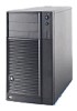
Intel® Entry Server Chassis SC5299-E Technical Product Specification Intel order number D37594-005 Revision 3.1 May 2010 Enterprise Platforms and Services Marketing - Intel SC5299BRP | Product Specification - Page 2
Revision History Intel® Entry Server Chassis SC5299-E TPS Revision History Date April 2006 December 2006 July 2007 November 2007 December information to SC5299-E family. 3.0 Updated section 1.1 and section 8. 3.1 Deleted CCC and CNCA content. ii Revision 3.1 Intel order number D37594-005 - Intel SC5299BRP | Product Specification - Page 3
absence or characteristics of any features or instructions marked "reserved" or "undefined." Intel reserves these for future definition and Intel Corporation server baseboards contain a number of high-density VLSI and power delivery components that need adequate airflow to cool. Intel's own chassis - Intel SC5299BRP | Product Specification - Page 4
® Entry Server Chassis SC5299-E Design Features 1 1.2 Chassis Views ...3 1.3 System Color...6 1.4 Chassis Security ...6 1.5 I/O Panel ...6 1.6 Rack and Cabinet Mounting Option 6 1.7 Front Bezel Features 7 1.8 Peripheral Bays ...7 2. Power Sub-system...8 2.1 420-Watt Power Supply - Intel SC5299BRP | Product Specification - Page 5
(Hard-wired 76 2.4.6 PSMI (Power Supply Monitoring Interface 79 2.5 670-W Power Supply 80 2.5.1 Mechanical Overview 80 2.5.2 3. Chassis Cooling ...105 3.1 Fan Configuration 105 3.2 Server Board Fan Control 105 3.3 Cooling Solution...106 4. Peripheral and Hard Drive Support 107 - Intel SC5299BRP | Product Specification - Page 6
Fan Connector...124 7.2.4 Chassis Intrusion Cable 124 7.3 Server Board Internal Cables 124 7.4 Accessory Cables 124 7.5 I/O Panel Connectors 124 7.6 Spares and Accessories 125 8. Supported Intel® Server 134 9.9 Serviceability and Availability 135 vi Revision 3.1 Intel order - Intel SC5299BRP | Product Specification - Page 7
Intel® Entry Server Chassis SC5299-E TPS Table of Contents 9.10 Calculated MTBF...135 Appendix A: Integration and Usage Tips 137 Glossary ...138 Revision 3.1 vii Intel order number D37594-005 - Intel SC5299BRP | Product Specification - Page 8
84 Figure 19. Output Voltage Timing 99 Figure 20. Turn On/Off Timing (Power Supply Signals 101 Figure 21. Cooling Fan Configuration 106 Figure 22. Drive Bay Locations for Intel® Entry Server Chassis SC5299-E (DP/WS/BRP configuration shown) ...107 Figure 23. 6-HDD Fixed Drive Bay, Rear Isometric - Intel SC5299BRP | Product Specification - Page 9
Intel® Entry Server Chassis SC5299-E TPS List of Figures Figure 29. Local Control Panel Components 122 Revision 3.1 ix Intel order number D37594-005 - Intel SC5299BRP | Product Specification - Page 10
of Tables Intel® Entry Server Chassis SC5299-E TPS List of Tables Table 1. Intel® Entry Server Chassis SC5299-E UP, DP, BRP, and WS Features 2 Table 2. Environmental Requirements 10 Table 3. Cable Lengths...12 Table 4. P1 Baseboard Power Connector 12 Table 5. P2 Processor Power Connector 13 - Intel SC5299BRP | Product Specification - Page 11
Intel® Entry Server Chassis SC5299-E TPS List of Tables Table 33. P3, P4, P6, P7, P8, P9 Peripheral Power Connectors 33 Table 34. P5 Floppy Power Connector 34 Table 35. P10 SATA Power Connectors 34 Table 36. P11 SATA Power Connectors 34 Table 37. Load Ratings...35 Table 38. Power On Load - Intel SC5299BRP | Product Specification - Page 12
of Tables Intel® Entry Server Chassis SC5299-E TPS Table 68. PSKILL Signal Characteristics 60 Table 69. PWOK Signal Characteristics 60 Table 70. LED Indicators ...61 Table 71. SMBus Device Addressing 62 Table 72. Environmental Requirements 63 Table 73. Edge Finger Power Supply Connector Pin - Intel SC5299BRP | Product Specification - Page 13
Intel® Entry Server Chassis SC5299-E TPS List of Tables Table 103. 12V4 Power Connector 87 Table 104. PCI Express Connector 87 Table 105. Peripheral Power Connectors 87 Table 106. P7 Right-angle Peripheral Power Connector 88 Table 107. P5 Floppy Power Connector 88 Table 108. P12 Right-angle - Intel SC5299BRP | Product Specification - Page 14
118 Table 139. Control Panel LED Functions 121 Table 140. IPMI Header...123 Table 141. System Office Environment Summary 134 Table 142. System BTU Information Table 134 Table 143. Mean Time To Repair Estimate 135 Table 144. Intel® Entry Server Chassis SC5299-E Component MTBF 136 xiv - Intel SC5299BRP | Product Specification - Page 15
Intel® Entry Server Chassis SC5299-E TPS List of Tables Revision 3.1 xv Intel order number D37594-005 - Intel SC5299BRP | Product Specification - Page 16
ƒ SC5299BRP - 650-W 1+1 redundant PSU for dual-processor server boards The UP, DP and WS power supply configurations each include an Intel validated PSU with an integrated cooling fan and one AC line input. The BRP power supply configuration includes (1 of 2) redundant Intel validated PSU with - Intel SC5299BRP | Product Specification - Page 17
7 slots and support for 6 full-length with tail card guide Form Factor 5.2U tower, convertible to 6U rack mount Front Panel LEDs for NIC1, NIC2, HDD activity, power status, and system fault status. Switches for power, NMI, and reset. Integrated temperature sensor for fan speed management - Intel SC5299BRP | Product Specification - Page 18
Intel® Entry Server Chassis SC5299-E TPS Product Overview Configuration connectors Color Construction Chassis ABS Dimensions Pedestal Dimensions Rack SC5299UP SC5299DP SC5299BRP SC5299WS Black 1.0-mm, zinc-plated sheet metal, meets Intel Cosmetic Spec # C25432 Fire retardant, non- brominated, - Intel SC5299BRP | Product Specification - Page 19
Product Overview Intel® Entry Server Chassis SC5299-E TPS A B E C F G H D I J TP00866 A. Power supply (fixed power supply shown) B. AC input power connector C. I/O Ports D. Expansion slot covers E. Alternate external SCSI knockout F. 120-mm system fan G. Serial B port knockout H. Location - Intel SC5299BRP | Product Specification - Page 20
Intel® Entry Server Chassis SC5299-E TPS Product Overview AF000447 Figure 3. Front Internal Chassis View of Intel® Entry Server Chassis SC5299-E(DP/WS/BRP configuration shown) TP00868 Figure 4. Rear Internal Chassis View of Intel® Entry Server Chassis SC5299-E with Optional Hotswap Drive Bay - Intel SC5299BRP | Product Specification - Page 21
includes the chassis slide rails, rack handle, rack orientation label, screws, and manual. This rack mount kit is designed to meet the EIA-310-D enclosure specification. General rack compatibility is further described in the Server Rack Cabinet Compatibility Guide found at http://intel.com/support - Intel SC5299BRP | Product Specification - Page 22
Intel® Entry Server Chassis SC5299-E TPS Product Overview 1.7 Front Bezel Features The bezel is constructed of molded plastic and attaches to the front of the chassis with three clips on the right side and two snaps on the left. The snaps at the left attach behind the access cover, thereby - Intel SC5299BRP | Product Specification - Page 23
Sub-system 2. Power Sub-system Intel® Entry Server Chassis SC5299-E TPS 2.1 420-Watt Power Supply The 420-W power supply specification defines a non-redundant power supply that supports DP Intel® Xeon™ entry server systems. The 420-W power supply has 6 outputs: 3.3V, 5V, 12V1, 12V2, -12V and 5VSB - Intel SC5299BRP | Product Specification - Page 24
Intel® Entry Server Chassis SC5299-E TPS 2.1.1 Mechanical Overview Power Sub-system Figure 6. Mechanical Drawing for Power Supply Enclosure Revision 3.1 9 Intel order number D37594-005 - Intel SC5299BRP | Product Specification - Page 25
Sub-system Intel® Entry Server Chassis SC5299-E TPS 2.1.2 Airflow and Temperature The power supply operates within all specified limits over the Top temperature range. The average air temperature difference ( Tps ) from the inlet to the outlet of the power supply does not exceed 20C. All airflow - Intel SC5299BRP | Product Specification - Page 26
Intel® Entry Server Chassis SC5299-E TPS Power Sub-system Figure 7. Output Cable Harness for 420-W Power Supply NOTES: 1. ALL DIMENSIONS ARE IN MM 2. ALL TOLERANCES ARE +10 MM/-0 MM 3. INSTALL 1 TIE WRAP WITHIN 12MM OF THE PSU CAGE 4. MARK REFERENCE DESIGNATOR ON EACH CONNECTOR 5. TIE WRAP EACH - Intel SC5299BRP | Product Specification - Page 27
Sub-system Intel® Entry Server Chassis SC5299-E TPS Table 3. Cable Lengths From To connector # Length (mm) Power Supply cover exit hole P1 425 Power Supply cover exit hole P2 425 Power Supply cover exit hole P3 250 Extension P4 100 Extension from P4 P5 100 Power Supply cover exit - Intel SC5299BRP | Product Specification - Page 28
Intel® Entry Server Chassis SC5299-E TPS Power Sub-system Pin 10 11 12 Signal +12V2 +12V2 +3.3 VDC 18 AWG COM +5 VDC Signal 18 AWG Color Blue/White Black Black Red 2.1.3.4 P10 Right-angle, P11 SATA Power Connectors Connector Housing: Contact: Revision 3.1 13 Intel order number D37594-005 - Intel SC5299BRP | Product Specification - Page 29
Sub-system Intel® Entry Server Chassis SC5299-E TPS Table 7. P10 Right-angle SATA Power Connector Pin 1 2 3 4 5 +3.3V Ground +5V Ground +12V2 Signal 24 AWG Color Orange Black Red Black Blue/White 2.1.4 AC Input Requirements The power supply operates within all specified limits over the - Intel SC5299BRP | Product Specification - Page 30
Entry Server Chassis SC5299-E TPS Power Sub-system less (20ms min) does not cause any tripping of control signals or protection circuits (= 20ms holdup time requirement). If the AC dropout lasts longer than one cycle, the power will recover and meet all turn on requirements. The power supply meets - Intel SC5299BRP | Product Specification - Page 31
Power Sub-system Intel® Entry Server Chassis SC5299-E TPS Table 9. AC Line Sag Transient Performance Duration Continuous 0 do they cause any nuisance trips of any of the power supply protection circuits The power supply meets surge-withstand test conditions under maximum and minimum DC-output - Intel SC5299BRP | Product Specification - Page 32
Intel® Entry Server Chassis SC5299-E TPS Power Sub-system 2.1.5.3 Remote Sense The power supply has remote sense return (ReturnS) to regulate out ground drops for all output voltages; +3.3V, +5V, +12V1, +12V2, -12V, and 5VSB. The power supply uses remote sense (3.3VS) to regulate out drops in - Intel SC5299BRP | Product Specification - Page 33
Sub-system Intel® Entry Server Chassis SC5299-E TPS 2.1.5.5 Voltage Regulation The power supply output voltages are within ReturnS). The 5V, 12V1, 12V2, -12V and 5VSB outputs are measured at the power supply connectors referenced to ReturnS. The +3.3V is measured at the remote sense signal (3. - Intel SC5299BRP | Product Specification - Page 34
Intel® Entry Server Chassis SC5299-E TPS Power Sub-system 2.1.5.7 Capacitive Loading The power supply is stable and meets all requirements other during turn off. The following figure shows the timing requirements for the power supply being turned on and off via the AC input, with PSON held low - Intel SC5299BRP | Product Specification - Page 35
Power Sub-system Intel® Entry Server Chassis SC5299-E TPS Item Tvout_rise Tvout_on T vout_off Table 16. Output Voltage Timing Description Minimum Output voltage rise after loss of AC. Minimum Maximum Units 1000 msec 2500 msec 21 msec 20 Revision 3.1 Intel order number D37594-005 - Intel SC5299BRP | Product Specification - Page 36
Intel® Entry Server Chassis SC5299-E TPS Power Sub-system Item Tpwok_holdup Tpson_on_delay Tpson_pwok Tpwok_on for 15 sec and a PSON# cycle HIGH for 1sec will reset the power supply. 2.1.6.1 Over-Current Protection (OCP) The power supply has a current limit to prevent the +3.3V, +5V, and +12V - Intel SC5299BRP | Product Specification - Page 37
Sub-system Intel® Entry Server Chassis SC5299-E TPS limits. The values are measured at the output of the power supply's connectors. The voltage never exceeds the maximum levels when measured at the power pins of the power supply connector during any single point of fail. The voltage will not trip - Intel SC5299BRP | Product Specification - Page 38
Intel® Entry Server Chassis SC5299-E TPS Power Sub-system Table 19. PSON# Signal Characteristic Signal Type PSON# = Low PSON# = High or Open Logic level low (power supply ON) Logic level high (power supply OFF) Source current, Vpson = low Power up delay: Tpson_on_delay PWOK delay: T pson_pwok - Intel SC5299BRP | Product Specification - Page 39
Server Chassis SC5299-E TPS 2.2 550-Watt Power Supply The 550-W power supply specification defines a non-redundant power supply that supports dual-processor Intel® Xeon® entry server systems. The 550-W power supply has 6 outputs: 3.3V, 5V, 12V1, 12V2, -12V and 5VSB. The form factor is SSI EPS12V - Intel SC5299BRP | Product Specification - Page 40
power supply shall incorporate an 80-mm fan for self cooling and system cooling. The airflow direction shall be from the wire internal face of the power supply to the external face. The power supply shall have adequate airflow with the following system airflow restriction. Revision 3.1 25 Intel - Intel SC5299BRP | Product Specification - Page 41
Sub-system Intel® Entry Server Chassis SC5299-E TPS System Pressure (in H2O) System Flow Impedance 0.6 0.5 0.4 0.3 0.2 0.1 0 0 10 20 30 40 Power Supply Airflow (CFM) Figure 10. System Airflow Impedance 2.2.1.2 Acoustic Requirements The fans speed shall vary linearly based on output - Intel SC5299BRP | Product Specification - Page 42
Entry Server Chassis SC5299-E TPS Power Sub-system Table 22. Environmental Requirements Item Description MIN Top Operating temperature range. 0 Tnon-op Non-operating temperature range. -40 Altitude Maximum operating altitude Specification 45 70 1500 Units C C m The power supply meets - Intel SC5299BRP | Product Specification - Page 43
Power Sub-system Intel® Entry Server Chassis SSI document EPS Power Supply spec limits. Temporary loss of function is allowed provided the function is self-recoverable or can be restored by the operation of the controls. 2.2.2.3.1 Electrostatic Discharge Susceptibility The power supply - Intel SC5299BRP | Product Specification - Page 44
Intel® Entry Server Chassis SC5299-E TPS Power Sub-system 2.2.2.3.2 Fast Transient/Burst The power supply complies with the limits no unsafe operation is allowed under any condition; all power supply output voltage levels must stay within proper spec levels; no change in operating state or loss - Intel SC5299BRP | Product Specification - Page 45
Power Sub-system Intel® Entry Server Chassis SC5299-E TPS Table 27. AC Line Dropout/Holdup Output of its critical components (including input fuse, bulk rectifiers, and surge limiting device). The power supply must meet the inrush requirements for any rated AC voltage, during turn on at any - Intel SC5299BRP | Product Specification - Page 46
Intel® Entry Server Chassis SC5299-E TPS Power Sub-system 2.2.2.8 AC Line Isolation Requirements The power supply meets all safety agency requirements for dielectric strength. Transformers' isolation between primary and secondary windings complies with the 3000Vac (4242Vdc) dielectric strength - Intel SC5299BRP | Product Specification - Page 47
-system Intel® Entry Server Chassis SC5299-E TPS Table 29. Cable Lengths From Power Supply cover exit hole Power Supply cover exit hole Power Supply cover exit hole Power Supply cover exit hole Extension from P3 Extension from P4 Power Supply cover exit hole Extension from P8 Power Supply cover - Intel SC5299BRP | Product Specification - Page 48
Intel® Entry Server Chassis SC5299-E TPS Power Sub-system Pin 12 Signal +3.3 VDC 18 AWG Color Orange Pin 24 Signal COM 18 AWG Color Black Note: 5V Remote sense may be double crimped into pin 4 if required to meet voltage regulation at the output connectors. 2.2.4.3 P2 Processor Power Power - Intel SC5299BRP | Product Specification - Page 49
Sub-system Intel® Entry Server Chassis SC5299-E TPS 2.2.4.6 P5 Floppy Power Connector Connector housing: AMP* 171822-4 or equivalent Contact: Amp 170204-1 contact or equivalent Table 34. P5 Floppy Power Connector Pin 1 2 3 4 +5VDC COM COM +12V2 Signal 22 AWG Color Red Black Black Green - Intel SC5299BRP | Product Specification - Page 50
Intel® Entry Server Chassis SC5299-E TPS Pin 4 5 COM +12V2 Signal Power Sub-system 18 AWG Color Black Green 2.2.4.9 Output Power/Currents The following table defines power and current ratings for the 550-W power supply. The combined output power of all outputs does not exceed the rated output - Intel SC5299BRP | Product Specification - Page 51
Intel® Entry Server Chassis SC5299-E TPS Voltage +3.3 V +5 V +12 V1 +12 V2 -12 V +5 VSB Table 38. Power On Load Ratings Minimum Continuous 0 A 0 A 0 A 0.1 A 0 A 0.1 A Maximum Continuous 9 A 7 A 16 A 5 A 0.5 A 3.0 A Peak 3.5 A Parameter + 3.3V + 5V + 12V1 + 12V2 - 12V + 5VSB Table 39. Power - Intel SC5299BRP | Product Specification - Page 52
Intel® Entry Server Chassis SC5299-E TPS Power Sub-system ground return. The current in any remote sense line is less than 5 mA to prevent voltage sensing errors. The power supply operates within specification over the full range of voltage drops from the power supply's output connector to the - Intel SC5299BRP | Product Specification - Page 53
Power Sub-system Intel® Entry Server Chassis SC5299-E TPS Output +12V1 +12V2 Step Load Size ( 700 11,000 350 350 Units F F F F F 2.2.4.17 Closed Loop Stability The power supply is unconditionally stable under all line/load/transient load conditions, including capacitive load ranges. A minimum - Intel SC5299BRP | Product Specification - Page 54
Intel® Entry Server Chassis SC5299-E TPS +3.3V 50mVp-p Table 43. Ripple and Noise +5V 50mVp-p +12V1/2 120mVp-p -12V 120mVp-p Power Sub-system +5VSB 50mVp-p 2.2.4.20 Soft Starting The power supply contains a control circuit that provides monotonic soft start for its outputs without - Intel SC5299BRP | Product Specification - Page 55
Power Sub-system V out Intel® Entry Server Chassis SC5299-E TPS 10% V out V1 V2 V3 V4 Tvout_rise Tvout_on Tvout_off Figure 11. Output Voltage Timing TP02313 Units 1500 msec 2500 msec msec msec 400 msec 50 msec 500 msec msec msec 40 Revision 3.1 Intel order number D37594-005 - Intel SC5299BRP | Product Specification - Page 56
Intel® Entry Server Chassis SC5299-E TPS Power Sub-system Item Tsb_vout T5VSB_holdup Description Delay from on/off cycle Figure 12. Turn On/Off Timing (Power Supply Signals) 2.2.4.23 Residual Voltage Immunity in Standby Mode The power supply is immune to any residual voltage placed on its - Intel SC5299BRP | Product Specification - Page 57
Sub-system Intel® Entry Server Chassis SC5299-E TPS 2.2.5.1 Over-current Protection (OCP) The power supply has a current limit to prevent the +3.3V, +5V, and +12V outputs from exceeding the values shown in the following table. If the current limits are exceeded, the power supply will shut down - Intel SC5299BRP | Product Specification - Page 58
Intel® Entry Server Chassis SC5299-E TPS Power Sub-system 2.2.5.3 Over-temperature Protection (OTP) The power supply is protected against over-temperature conditions caused by loss of fan cooling or excessive ambient temperature. In an OTP condition the power supply unit will shut down. When the - Intel SC5299BRP | Product Specification - Page 59
Intel® Entry Server Chassis SC5299-E TPS Table 49. PWOK Signal Characteristics Signal Type PWOK = High PWOK = Low Logic level low voltage, Isink=4mA Logic level high voltage, Isource=200 A Sink current, PWOK = low Source current, PWOK = high PWOK delay: Tpwok_on PWOK rise and fall time Power - Intel SC5299BRP | Product Specification - Page 60
Intel® Entry Server Chassis SC5299-E TPS Power Sub-system 2.3 650-W Power Supply Module The 650-W power supply module specification defines a 1+1 redundant power supply that supports a dual-processor Intel® Xeon® server system. The power supply has two outputs to power the system: 12VDC and 5VSB. - Intel SC5299BRP | Product Specification - Page 61
Power Sub-system Intel® Entry Server Chassis SC5299-E TPS Table 50. Acoustic Requirements Operating Conditions Maximum LED Marking and Identification The LED is green or amber when lit. 2.3.2 AC Input Requirements The 650-W power supply incorporates a universal power input with active power - Intel SC5299BRP | Product Specification - Page 62
Intel® Entry Server Chassis SC5299-E TPS Power Sub-system 2.3.2.2 Efficiency The power supply has a minimum efficiency of 75% at maximum load and over an 90-264VAC line voltage range to guarantee proper power supply cooling while mounted in the system. 2.3.2.3 AC Input Voltage Specification - Intel SC5299BRP | Product Specification - Page 63
Power Sub-system Intel® Entry Server Chassis SC5299-E TPS Duration > 1 AC cycle Sag Operating AC Voltage > cage with an external EMI filter that meets the criteria defined in the SSI document EPS Power Supply Specification. Table 55. Performance Criteria Level A B C Description The apparatus - Intel SC5299BRP | Product Specification - Page 64
Intel® Entry Server Chassis SC5299-E TPS Power Sub-system 2.3.2.7.1 Electrostatic Discharge Susceptibility The power supply complies with No unsafe operation allowed under any condition; all power supply output voltage levels remain within proper spec levels; no change in operating state or loss - Intel SC5299BRP | Product Specification - Page 65
Power Sub-system Intel® Entry Server Chassis SC5299-E TPS 2.3.2.8.1 AC Line 5VSB Holdup The 5VSB output voltage stays in regulation under its full load (static or dynamic) during an AC dropout of 70ms min (=5VSB holdup time) whether the power supply is in an ON or OFF state (PSON asserted or de- - Intel SC5299BRP | Product Specification - Page 66
Intel® Entry Server Chassis SC5299-E TPS Power Sub-system primary and secondary circuits, and primary to ground circuits, complies with the IEC 950 spacing requirements. 2.3.2.12 Power Factor Correction The power supply incorporates a power factor correction circuit. The power supply has been - Intel SC5299BRP | Product Specification - Page 67
Power Sub-system Intel® Entry Server Chassis SC5299-E TPS Connector Upper Side + power supply. 2.3.3.4 Output Power/Currents The following table defines power and current ratings for the 650-W continuous (720-W pk) power supply in a 1+0 or 1+1 redundant configuration. The combined output power - Intel SC5299BRP | Product Specification - Page 68
Intel® Entry Server Chassis SC5299-E TPS Table 58. Power Supply Module Load Ratings Voltage +12 V +5 VSB Min 0 A 0.1 A 650-W Max 54 A 3.0 A Peak 58 A 3.5 A Power Sub-system 2.3.3.5 Standby Output The 5VSB output is present when an AC input greater than the power supply turn-on voltage is - Intel SC5299BRP | Product Specification - Page 69
Sub-system Intel® Entry Server Chassis SC5299-E TPS 2.3.3.8 Capacitive Loading The power supply is stable and meets all requirements with the following capacitive loading ranges. Minimum capacitive loading applies to static load only. Table 61. Capacitive Loading Conditions - Intel SC5299BRP | Product Specification - Page 70
Intel® Entry Server Chassis SC5299-E TPS Power Sub-system 2.3.3.13 Timing Requirements The timing requirements for power supply All outputs rise monotonically. The following figure shows the timing requirements for the power supply being turned on and off via the AC input, with PSON held - Intel SC5299BRP | Product Specification - Page 71
Power Sub-system Intel® Entry Server Chassis SC5299-E TPS Table 64. Turn On/Off Timing Item Description Minimum Tsb_on_delay Delay from AC being applied to 5VSB being within regulation. Tac_on_delay Delay from - Intel SC5299BRP | Product Specification - Page 72
Intel® Entry Server Chassis SC5299-E TPS Power Sub-system 2.3.3.15 Residual Voltage Immunity in Standby Mode The power supply is immune to any residual voltage placed on its 12V output (typically a leakage voltage through the system from standby output) up to 1000 mV. This - Intel SC5299BRP | Product Specification - Page 73
Sub-system Intel® Entry Server Chassis SC5299-E TPS 2.3.4.2 Over-voltage Protection (OVP) The power supply's over-voltage protection is locally sensed. The power supply will shut down and latch off after an over-voltage condition occurs. This latch can be cleared by toggling the PSON# signal - Intel SC5299BRP | Product Specification - Page 74
Intel® Entry Server Chassis SC5299-E TPS Power Sub-system Table 67. PSON# Signal Characteristic Signal Type PSON# = Low PSON# = High or Open Logic level low (power supply ON) Logic level high (power supply OFF) Source current, Vpson = low Power up delay: Tpson_on_delay PWOK delay: T pson_pwok - Intel SC5299BRP | Product Specification - Page 75
-system Intel® Entry Server Chassis SC5299-E TPS Table 68. PSKILL Signal Characteristics Signal Type (Input Signal to Supply) PSKILL = Low, PSON# = Low PSKILL = Open, PSON# = Low or Open PSKILL = Low, PSON# = Open Accepts a ground input from the system. Pull-up to VSB located in the power supply - Intel SC5299BRP | Product Specification - Page 76
Intel® Entry Server Chassis SC5299-E TPS Power Sub-system 2.3.5.4 LEDs There is a bi-color LED and a single color LED to indicate power supply status. The LED operation is defined in the following table. Table 70. LED Indicators Power Supply Condition AC Power Off AC power on in Standby AC On - Intel SC5299BRP | Product Specification - Page 77
Sub-system Intel® Entry Server Chassis SC5299-E TPS 2.3.6.1 Device Address Locations The power supply plus power distribution board (PS+PDB) device address locations are shown in the following table. There are two signals to set the address location of the power supply once it is installed - Intel SC5299BRP | Product Specification - Page 78
Intel® Entry Server Chassis SC5299-E TPS 2.4.1 Mechanical Overview Power Sub-system Figure 14. Mechanical Drawing for Dual (1+1 Configuration) Power Supply Enclosure 2.4.1.1 Airflow Requirements There is no fan in the cage; the cage is cooled by the fan in the power supply module(s) when - Intel SC5299BRP | Product Specification - Page 79
Power Sub-system Intel® Entry Server Chassis SC5299-E TPS Item Tnon-op Altitude Description Non- range. 2.4.2 DC Output Specification 2.4.2.1 Input Connector (Power Supply Mating Connector) Table 73. Edge Finger Power Supply Connector Pin-out Connector Gold finger edge connector: 2X24 - Intel SC5299BRP | Product Specification - Page 80
Intel® Entry Server Chassis SC5299-E TPS Power Sub-system Connector Upper Side +12V Return 5VSB Lengths From Length (mm) Power Supply cover exit hole 450 Power Supply cover exit hole 580 Power Supply cover exit hole 450 Power Supply cover exit hole 550 Power Supply cover exit hole 290 - Intel SC5299BRP | Product Specification - Page 81
Sub-system Intel® Entry Server Chassis SC5299-E TPS 2.4.2.3 Baseboard Power Connector (P1) Connector housing: 24-Pin Molex* Mini-Fit Jr. 39-01-2245 or equivalent Contact: Molex Mini-Fit, HCS, Female, Crimp 44476 or equivalent Table 75. P1 Baseboard Power Connector Pin 1* 2 3* 4* 5 6 7 8 9 10 - Intel SC5299BRP | Product Specification - Page 82
Intel® Entry Server Chassis SC5299-E TPS Power Sub-system 2.4.2.4 Processor Power Connector (P2) Connector housing: 8-Pin Molex* 39-01-2080 or equivalent Contact: Molex Mini-Fit, HCS, Female, Molex 44476 or equivalent Table 76. P2 Processor Power Connector Pin 1 2 3 4 Signal COM COM COM COM - Intel SC5299BRP | Product Specification - Page 83
Sub-system Intel® Entry Server Chassis SC5299-E TPS 2.4.2.7 Peripheral Power Connectors (P3, P4, P6, P7, P8, P9) Connector housing: Amp* 1-480424-0 or equivalent Contact: Amp 61314-1 contact or equivalent Table 79. Peripheral Power Connectors Pin Signal 18 AWG Color 1 +12V4 Green 2 COM - Intel SC5299BRP | Product Specification - Page 84
Intel® Entry Server Chassis SC5299-E TPS Power Sub-system Table 82. SATA Power the +3.3V and 5V outputs. Also, the power supply ground return remote sense (ReturnS) passes through A. 2. Peak power and current loading shall be supported for a minimum of 12 seconds. 3. 12V5 is the power source for the - Intel SC5299BRP | Product Specification - Page 85
Power Sub-system Intel® Entry Server Chassis SC5299-E TPS 2.4.2.13 DC/DC Converters Loading The following table defines the power and current ratings for the three DC/DC converters located on the cage; each is powered Vrms See Power Supply Specification; measured at the power distribution board - Intel SC5299BRP | Product Specification - Page 86
Intel® Entry Server Chassis SC5299-E TPS Power Sub-system kHz at duty cycles ranging from 10%-90%. The load 250 6,800 F +5VDC 400 4,700 F -12VDC 1 350 F Note: Refer to the Power Supply specification for the equivalent data on +12V and +5VSB output. 2.4.3.2 DC/DC Converters Closed Loop - Intel SC5299BRP | Product Specification - Page 87
Power Sub-system Intel® Entry Server Chassis SC5299-E TPS 2.4.3.4 DC/DC Converters Ripple/Noise -p Note: Refer to the Power Supply specification for the equivalent data on +12V and +5VSB output. 2.4.3.5 Fan Operation in Standby Mode The fans on the power distribution board continue to operate - Intel SC5299BRP | Product Specification - Page 88
Intel® Entry Server Chassis SC5299-E TPS Power Sub-system V out 10% V out V1 V2 V3 V4 Tvout_rise Tvout_on Tvout_off Figure 15. Output Voltage Timing TP02313 Table 90 Minimum 21 20 5 100 Maximum 1500 2500 400 50 500 Units ms ms ms ms ms ms ms Revision 3.1 73 Intel order number D37594-005 - Intel SC5299BRP | Product Specification - Page 89
Power Sub-system Intel® Entry Server Chassis SC5299-E TPS Item Description Tpwok_off Delay from PWOK de-asserted to output /off cycle PSON turn on/off cycle Figure 16. Turn On/Off Timing (Power Supply Signals) 2.4.3.7 Residual Voltage Immunity in Standby Mode Each DC/DC converter is immune - Intel SC5299BRP | Product Specification - Page 90
Intel® Entry Server Chassis SC5299-E TPS Power Sub-system Residual voltage at the power supply outputs for no load condition do not exceed 100mV when AC voltage is applied and the PSON# signal is de-asserted. 2.4.3.8 Soft Start Requirements The power supply contains a control circuit, which - Intel SC5299BRP | Product Specification - Page 91
Power Sub-system Intel® Entry Server Chassis SC5299-E TPS 2.4.4.2 Over-voltage Protection (OVP) (V) OVP MAX (V) 3.9 4.5 5.7 6.5 -13.3 -14.5 See Power Supply specification See Power Supply specification 2.4.5 Control and Indicator Functions (Hard-wired) The following sections define - Intel SC5299BRP | Product Specification - Page 92
Intel® Entry Server Chassis SC5299-E TPS Power Sub-system Table 93. PSON# Signal Characteristics Signal Type PSON# = Low PSON# = High or Open Logic level low (power supply ON) Logic level high (power supply OFF) Source current, Vpson = low Power up delay: Tpson_on_delay PWOK delay: T pson_pwok - Intel SC5299BRP | Product Specification - Page 93
Power Sub-system Intel® Entry Server Chassis SC5299-E TPS Table 94. PWOK Signal Characteristics Signal Type PWOK = High PWOK = Low Open collector/drain output from power supply. Pull-up to VSB located in system. Power OK Power Not OK Logic level low voltage, Isink=4mA Logic level high voltage, - Intel SC5299BRP | Product Specification - Page 94
Intel® Entry Server Chassis SC5299-E TPS Power Sub-system 2.4.6 PSMI (Power Supply Monitoring Interface) The power supply and cage combination provide a monitoring interface to the system over a server management bus to the system. The device is compatible with both SMBus 2.0 'high power' and - Intel SC5299BRP | Product Specification - Page 95
2.5 670-W Power Supply The 670-W specification defines a non-redundant power supply that supports entry server systems. This 670-W power supply has 8 outputs: 3.3V, 5V, 12V1, 12V2, 12V3, 12V4, -12V and 5VSB. The power supply contains a single 80-mm fan for cooling the power supply and part of the - Intel SC5299BRP | Product Specification - Page 96
Intel® Entry Server Chassis SC5299-E TPS Power Sub-system Figure 17. Mechanical Drawing of the 670-W Power Supply Enclosure Revision 3.1 81 Intel order number D37594-005 - Intel SC5299BRP | Product Specification - Page 97
Power Sub-system Intel® Entry Server Chassis SC5299-E TPS 2.5.2 Acoustic Requirements The declared sound power level of the power supply assembly does not exceed the levels specified in the following table. Operating Conditions Maximum Operating Idle Table 97. Sound Power Requirement Inlet - Intel SC5299BRP | Product Specification - Page 98
Intel® Entry Server Chassis SC5299-E TPS Power Sub-system The power supply meets UL enclosure requirements for temperature rise limits. All sides of the power supply, with exception of the air exhaust side, are classified as "Handle, knobs, grips, etc., held for short periods of time only." 2.5.5 - Intel SC5299BRP | Product Specification - Page 99
Sub-system Intel® Entry Server Chassis SC5299-E TPS Notes: 1. All dimensions are in mm. 2. All tolerances are +15 mm/-0 mm 3. Install 1 tie wrap within 12mm of the power supply cage. 4. Mark reference designator on each connector. 5. Tie wrap each harness at approximately mid point. Figure 18 - Intel SC5299BRP | Product Specification - Page 100
Intel® Entry Server Chassis SC5299-E TPS Power Sub-system 2.5.6 Power Connectors 2.5.6.1 Baseboard Power Connector (P1) Connector housing: 24-Pin Molex* Mini-Fit Jr. 39-01-2245 or equivalent Contact: Molex Mini-Fit, HCS, Female, Crimp 44476 or equivalent Table 100. P1 Baseboard Power - Intel SC5299BRP | Product Specification - Page 101
Sub-system Intel® Entry Server Chassis SC5299-E TPS 2.5.6.2 Processor Power Connector (P2) Connector housing: 8-Pin Molex* 39-01-2080 or equivalent Contact: Molex 44476-1111 or equivalent Table 101. P2 Processor Power Connector Pin 1 2 3 4 Signal COM COM COM COM 18 AWG Color Black Black - Intel SC5299BRP | Product Specification - Page 102
Intel® Entry Server Chassis SC5299-E TPS Power Sub-system 2.5.6.4 12V4 Power Connector (P16) Connector housing: 6-Pin Molex* 39-01-2040 or equivalent Contacts: Molex Mini-Fit, HCS, 44476-1111 or equivalent Table 103. 12V4 Power Connector Pin 1 2 Signal COM COM 18 AWG Color Black Black Pin 4 - Intel SC5299BRP | Product Specification - Page 103
Power Sub-system Intel® Entry Server Chassis SC5299-E TPS Table 106. P7 Right-angle Peripheral Power Connector Pin 1 2 3 4 Signal +12V4 COM COM +5 VDC Green Black Black Red 18 AWG Color 2.5.6.8 Floppy Power Connector (P5) Connector housing: Amp* 171822-4 or equivalent Contact: Amp 170204-1 - Intel SC5299BRP | Product Specification - Page 104
Intel® Entry Server Chassis SC5299-E TPS Table 109. P13 SATA Power Connector Pin Signal 1 +3.3V 2 COM 3 +5VDC 4 COM 5 +12V4 18 AWG Color Orange Black Red Black Green Power Sub-system 2.5.7 AC Input Requirements 2.5.7.1 Power Factor Correction The power supply incorporates a power - Intel SC5299BRP | Product Specification - Page 105
Power Sub-system Intel® Entry Server Chassis SC5299-E TPS Table 110. AC Input Rating Parameter MIN any phase of the AC line for any length of time. During an AC dropout, the power supply meets dynamic voltage regulation requirements. An AC line dropout of any duration does not cause any tripping - Intel SC5299BRP | Product Specification - Page 106
Intel® Entry Server Chassis SC5299-E TPS Power Sub-system 2.5.7.6 AC Line Fuse The power supply has one line fused in the single line fuse on the line (Hot) wire of the AC input. The line fusing is acceptable for all - Intel SC5299BRP | Product Specification - Page 107
Intel® Entry Server Chassis SC5299-E TPS Table 110. The peak in-rush current is less than the ratings of its critical components (including input fuse, bulk rectifiers, and surge limiting device). The power supply ; all power supply output voltage levels must stay within proper spec levels; - Intel SC5299BRP | Product Specification - Page 108
Intel® Entry Server Chassis SC5299-E TPS Power Sub-system The power supply complies with the limits defined in EN55024: 1998 using the IEC 61000-45:1995 test standard and performance criteria B defined in Annex B of CISPR 24. 2.5.7.9 - Intel SC5299BRP | Product Specification - Page 109
Sub-system Intel® Entry Server Chassis SC5299-E TPS 2.5.7.12 Power Recovery The power supply recovers automatically after an AC power failure. AC power failure is defined to be any loss of AC power that exceeds the dropout criteria. 2.5.7.12.1 Voltage Brown Out The power supply complies with - Intel SC5299BRP | Product Specification - Page 110
Intel® Entry Server Chassis SC5299-E TPS Power Sub-system The power supply operates within specification over the full range of voltage drops from the power supply's output connector to the remote sense points. 2.5.8.3 Output Power/Currents The following table defines the power and current - Intel SC5299BRP | Product Specification - Page 111
Power Sub-system Intel® Entry Server Chassis SC5299-E TPS Table 117. Voltage Regulation Limits Parameter + 3.3V + 5V + 12V1 + 12V2 +12V3 +12V4 - 12V + 5VSB Tolerance 1000 F 4700 F 20 F 2.5.8.7 Capactive Loading The power supply is stable and meets all requirements with the following - Intel SC5299BRP | Product Specification - Page 112
Intel® Entry Server Chassis SC5299-E TPS Output +5V +12V(1, 2, 3, 4) -12V +5VSB MIN 400 500 each 1 20 MAX 4700 11,000 350 350 Power Sub-system Units F F F F 2.5.8.8 Closed Loop Stability The power supply is unconditionally stable under all line/load/transient load conditions, including - Intel SC5299BRP | Product Specification - Page 113
Power Sub-system Intel® Entry Server Chassis SC5299-E TPS Voltage +5V +12V1 +12V2 +12V3 +12V4 -12V +5VSB Minimum Continuous Load 0 A 0.0 A 0.0 A 0.1 A 0.0 A 0 A This is measured over a bandwidth of 10Hz to 20MHz at the power supply output connectors. A 10 F tantalum capacitor, in parallel with a - Intel SC5299BRP | Product Specification - Page 114
Intel® Entry Server Chassis SC5299-E TPS Power Sub-system 2.5.8.14 Timing Requirements The timing requirements for power supply operation are as other during turn off. The following table shows the timing requirements for the power supply being turned on and off via the AC input, with PSON held - Intel SC5299BRP | Product Specification - Page 115
Power Sub-system Intel® Entry Server Chassis SC5299-E TPS Table 124. Turn On/Off Timing Item Tsb_on_delay Tac_on_delay Tvout_holdup Tpwok_holdup Tpson_on_delay Tpson_pwok Tpwok_on ms 2500 ms ms ms 400 ms 50 ms 500 ms ms ms 1000 ms ms 100 Revision 3.1 Intel order number D37594-005 - Intel SC5299BRP | Product Specification - Page 116
Intel® Entry Server Chassis SC5299-E TPS Power Sub-system AC Input Vout TAC_on_delay Tsb_on_delay PWOK for 15 sec and a PSON# cycle HIGH for 1 sec will reset the power supply. 2.5.9.1 Over-current Protection (OCP) The power supply has a current limit to prevent the +3.3V, +5V, and +12V outputs - Intel SC5299BRP | Product Specification - Page 117
Power Sub-system Intel® Entry Server Chassis SC5299-E TPS Voltage Over-current Limit MIN MAX Peak Load* The voltage will not trip any lower than the minimum levels when measured at the power pins of the power supply connector. The +5VSB rail will auto-recover after its OVP limit. Table 126. - Intel SC5299BRP | Product Specification - Page 118
Intel® Entry Server Chassis SC5299-E TPS Power Sub-system 2.5.9.3 Over-temperature Protection (OTP) The power supply is protected against over-temperature conditions caused by loss of fan cooling or excessive ambient temperature. In an OTP condition the power supply will shut down. When the - Intel SC5299BRP | Product Specification - Page 119
Sub-system Intel® Entry Server Chassis SC5299-E TPS 2.5.10.2 PWOK (Power OK) Output Signal PWOK is a power OK signal and is pulled HIGH by the power supply to indicate that all the outputs are within the regulation limits of the power supply. When any output voltage falls below regulation limits - Intel SC5299BRP | Product Specification - Page 120
Intel® Entry Server Chassis SC5299-E TPS Chassis Cooling 3. Chassis Cooling 3.1 Fan Configuration The cooling sub-system of the Intel® Entry Server Chassis SC5299-E consists of one system fan and one power supply fan (the SC5299WS configuration has an additional 92-mm drive bay fan). The 4-wire - Intel SC5299BRP | Product Specification - Page 121
provided for CPU cooling must be installed. Active heatsinks for CPUs incorporate a fan to provide cooling. This thermal solution is included with some boxed Intel® Xeon™ processors. The Intel® Entry Server Chassis SC5299-E is engineered to work with processors that have an active heatsink solution - Intel SC5299BRP | Product Specification - Page 122
The Intel® Entry Server Chassis SC5299-E supports two half-height 5.25-in removable media peripheral devices, such as a magnetic/optical disk, CD-ROM drive, or tape drive. These peripherals can be up to 9 inches (228.6 mm) deep on the non-redundant power chassis. The 650-W redundant power supply is - Intel SC5299BRP | Product Specification - Page 123
front of the chassis after taking off the access cover and removing the front bezel. The peripheral bay utilizes visual guide holes to correctly maximum power levels of the power supply are not exceeded. 4.3 Hard Disk Drive Bays 4.3.1 Fixed Hard Drive Bay The Intel® Entry Server Chassis SC5299 - Intel SC5299BRP | Product Specification - Page 124
controller on an add-in card. Each backplane type supports up to six 1-in hot swap drives when mounted in the docking drive carrier. 4.3.2 SAS Non-expander/Serial-ATA (SATA) Hot Swap Back Plane (HSBP) The Intel® Entry Server Chassis SC5299-E 6HDD SATA HSBP is a monolithic printed circuit board - Intel SC5299BRP | Product Specification - Page 125
Peripheral and Hard Drive Support Intel® Entry Server Chassis SC5299-E TPS SATA BACK PLANE BOARD - 6 PORT SATA HDD1 P.8 SATA 7PIN Conn1 P.7 STATUS DISPLAY LED P.9 SMBus P.2 POWER CONN P.4 Hardware Monitor & SAF-TE P.2 & P.3 Figure 24. Intel® Entry Server Chassis SC5299-E 6HDD SATA HSBP Block - Intel SC5299BRP | Product Specification - Page 126
Intel® Entry Server Chassis SC5299-E TPS Peripheral and Hard Drive Support 4.3.2.1 SATA Enclosure Management Controller The customization. These GPIOs are used for hardware drive detection and driving FAULT and ACTIVITY LEDs. The GEM424 controller comes in an 80-pin Thin Quad Flat Pack (TQFP) - Intel SC5299BRP | Product Specification - Page 127
Drive Support Intel® Entry Server Chassis SC5299-E TPS Addr = 0xA0 BOOT EEPROM 68 & 69 Port 2 GEM424 Addr = 0xA6 FRU EEPROM 72 & 73 Port 1 Addr = 0x90 Port 0 74 & 75 Temp Sensor Addr = 0xA2 RUN EEPROM SATA HOST Addr = 0xC0 IPMB Addr = 0xC0/C2 Figure 25. Intel® Entry Server Chassis SC5299 - Intel SC5299BRP | Product Specification - Page 128
Intel® Entry Server Chassis SC5299-E TPS Peripheral and Hard Drive Support Device Power Well ViH ViL VoL Ileak AT24C512 P5V 0.7VCC 24C02 EEPROM provides 2048 bits of serial electrically erasable and programmable read-only memory. The serial EEPROM has an I2C address of 0xA6h and resides on - Intel SC5299BRP | Product Specification - Page 129
Support Intel® Entry Server Chassis SC5299-E TPS GEM424 PIN I/O Power NAME Type Well Programming Description GPIO10 O 3.3V SATA HDD4 Status LED GPIO11 O 3.3V SATA HDD5 Status LED 7K to 5V Pull up 4.7K to 5V 4.3.2.5 External Memory Device The 6HDD SATA HSBP contains non-volatile 32K and 64K - Intel SC5299BRP | Product Specification - Page 130
Intel® Entry Server Chassis SC5299-E TPS Peripheral and Hard Drive Support Table 132. LED Function Status LED GREEN ON YELLOW ON YELLOW Blinking Definition HDD Activity HDD Fail Rebuild in progress 4.3.2.7 SATA Drive Connectors The 6HDD SATA HSBP provides six 22-pin - Intel SC5299BRP | Product Specification - Page 131
Peripheral and Hard Drive Support Intel® Entry Server Chassis SC5299-E TPS Connector Contact Number Power Connectors The 6HDD SATA HSBP provides two standard 4-pin hard drive power connectors. The following table defines the pin-out of the 4-pin power connectors (JP4 and JP5). Table 135. Power - Intel SC5299BRP | Product Specification - Page 132
Intel® Entry Server Chassis SC5299-E TPS Peripheral and Hard Drive Support 4.3.2.9 Clock Generation and Distribution The 6HDD SATA HSBP provides one clock source. A 20-MHz oscillator the SATA hot-swap backplane. Note: Secondary side is mirrored. Revision 3.1 117 Intel order number D37594-005 - Intel SC5299BRP | Product Specification - Page 133
and Hard Drive Support Intel® Entry Server Chassis SC5299-E TPS Figure 26. Intel® Entry Server Chassis SC5299-E 6HDD SATA Hot Swap Backplane Board Layout 4.3.2.13 Connector Specifications Table 138. SATA Hot-swap Backplane Connector Specifications Qty Manufacturer and Part Number 6 Amphenol - Intel SC5299BRP | Product Specification - Page 134
Intel® Entry Server Chassis SC5299-E TPS Supported Intel® Server Boards 4.3.2.14 SATA Hot Swap Drive Cage Upgrade Kit The SATA drive cage upgrade kit allows for installation of up to six SATA drives in the server. The kit includes a SATA hot-swap drive bay with mounting hardware. With this kit, - Intel SC5299BRP | Product Specification - Page 135
header for Intel® server boards is located on the back of the front panel. This allows for connection of a 24-pin ribbon cable for use with SSI rev 3.61compliant server boards. The connector cable is compatible with the 24-pin SSI standard. A B C D E F G H TP00872 A. Power/Sleep LED B. Power button - Intel SC5299BRP | Product Specification - Page 136
Disconnected Hard drive activity No activity Status LED Green ON BLINK Amber ON BLINK OFF System ready (not supported by all server boards) Processor or memory disabled Critical temperature or voltage fault; CPU/Terminator missing Power fault; Fan fault; Non-critical temperature or voltage fault - Intel SC5299BRP | Product Specification - Page 137
Intel® Entry Server Chassis SC5299-E TPS 6. Intel® Local Control Panel The Intel® Local Control Panel (iLCP) utilizes a combination of control buttons, LEDs the system. More information regarding the Intel® Local Control Panel can be found on the Intel support web site. The following diagram - Intel SC5299BRP | Product Specification - Page 138
Intel® Entry Server Chassis SC5299-E TPS Intel® Local Control Panel 6.1 Internal Control Panel Headers The control panel interface board has one internal header: A 4-pin header provides control and status information to/from the server board via the IPMB interface. A 4-pin round cable connects the - Intel SC5299BRP | Product Specification - Page 139
mounted USB connectors to the server board. 7.2.3 Fan Connector The installed system fan provides a 4-pin connector that is designed to mate with a SSI (ATX*)3 and 4-pin compatible fan header. 7.2.4 Chassis Intrusion Cable A 2-conductor chassis intrusion cable is included with the chassis kit - Intel SC5299BRP | Product Specification - Page 140
Rack mounting kit Replacement 550-W power supply for DP Replacement 650-W cage for DP 650-W module for BRP - upgrade to redundant or replacement Preventative maintenance kit: Plastic slide from fixed drive bay (2) CPU duct (2 separate parts) Intrusion switch assembly USB cable Front panel LED - Intel SC5299BRP | Product Specification - Page 141
Supported Intel® Server Boards Intel® Entry Server Chassis SC5299-E TPS 8. Supported Intel® Server Boards The Intel® Entry Server Chassis SC5299-E is mechanically and functionally designed to support the following Intel® server boards: ƒ Intel® Server Board S5000XVN ƒ Intel® Server Board S5000VSA - Intel SC5299BRP | Product Specification - Page 142
Intel® Entry Server Chassis SC5299-E TPS Regulatory, Environmentals, and Specifications 9. Regulatory, Environmentals, and Specifications 9.1 Product Regulatory Compliance WARNING To ensure regulatory compliance, you must adhere to the assembly instructions included with this chassis to ensure - Intel SC5299BRP | Product Specification - Page 143
Regulatory, Environmentals, and Specifications Intel® Entry Server Chassis SC5299-E TPS ƒ EN55024 - Immunity (Europe) ƒ EN61000-3-2 - Harmonics (Europe) ƒ as Blue Angels, Nordic White Swan, and Swedish TCO. All plastic parts that weigh >25gm are marked with the ISO11469 requirements for recycling. - Intel SC5299BRP | Product Specification - Page 144
SC5299-E TPS Regulatory, Environmentals, and Specifications 9.1.5 Product Regulatory Compliance Markings This Intel® server chassis product bears the following regulatory marks. Regulatory Compliance cULus Listing Marks Region USA/Canada Marking GS Mark CE Mark Germany Europe FCC Marking - Intel SC5299BRP | Product Specification - Page 145
Regulatory, Environmentals, and Specifications Intel® Entry Server Chassis SC5299-E TPS 9.2 Electromagnetic Compatibility Notices 9.2.1 FCC Verification Statement (USA) This device complies with Part 15 of the FCC Rules. Operation is subject to the following two conditions: (1) This device may - Intel SC5299BRP | Product Specification - Page 146
Intel® Entry Server Chassis equipment according to the instruction manual. 9.2.5 BSMI (Taiwan ) The BSMI Certification number and the following warning is located on the product safety label, which is located on the bottom side (pedestal orientation) or side (rack mount - Intel SC5299BRP | Product Specification - Page 147
other component will void the UL listing and other product certifications and approvals. ƒ Server Chassis - (Base chassis is provided with power supply and fans) UL listed. ƒ Server board - Must use an Intel® server board-UL recognized. ƒ Add-in boards - Must have a printed wiring board flammability - Intel SC5299BRP | Product Specification - Page 148
Intel® Entry Server Chassis SC5299-E TPS Regulatory, Environmentals, and Specifications - Cadmium 9.6 Replacing the Back up Battery The lithium battery on the server board powers the real time clock (RTC) for up to 10 years in the absence of power. When the battery starts to weaken, it loses - Intel SC5299BRP | Product Specification - Page 149
is often expressed in BTUs. The following table provides the BTU information for each SKU of the Intel® Entry Server Chassis SC5299-E. Power Supply SC5299UP (420W) SC5299DP (550W) SC5299BRP (650W) SC5299WS (670W) Table 142. System BTU Information Table Max Continuous Output 450W 550W 610W 670W - Intel SC5299BRP | Product Specification - Page 150
device Remove and replace fixed power supply module Remove and replace hot-swap power supply module Remove and replace drive cage fan Remove and replace system fan Remove and replace backplane board Remove and replace control panel board Remove and replace server board Time Estimate < 1 minute - Intel SC5299BRP | Product Specification - Page 151
. Intel® Entry Server Chassis SC5299-E Component MTBF Subassembly DP, WS Server Model DP, WS (Server in 35 degrees C ambient air) Power Supply Standard Configuration MTBF (hours) 100,000 FIT (flrs/10^9 hrs) 10,000 Power Supply (non-redundant with power distribution board) Cooling fan 500 - Intel SC5299BRP | Product Specification - Page 152
Make sure the latest system software is loaded on the server. This includes system BIOS, FRU/SDR, BMC firmware, and hot-swap controller firmware. The latest system software can be downloaded from: http://support.intel.com/support/motherboards/server/ Revision 3.1 137 Intel order number D37594-005 - Intel SC5299BRP | Product Specification - Page 153
Chassis SC5299-E TPS Glossary Word/Acronym ACA ANSI ATX Auto-Ranging BMC CFM CMOS Dropout EEB EMP FP FRB FRU HSBP Latch Off LCD LCP LPC Monotonically MTBF MTTR Noise OTP Definition Australian Communication Authority American National Standards Institute Advanced Technology Extended Power supply - Intel SC5299BRP | Product Specification - Page 154
' condition in the load attached to the supply. OVP Over Voltage Protection PDB Power Distribution Board PFC Power Factor Correction PSU Power Supply Unit PWOK A typical logic level output signal provided by the supply that signals the Server System that all DC output voltages are within
-
 1
1 -
 2
2 -
 3
3 -
 4
4 -
 5
5 -
 6
6 -
 7
7 -
8
-
9
-
10
-
11
-
12
-
13
-
14
-
15
-
16
-
17
-
18
-
19
-
20
-
21
-
22
-
23
-
24
-
25
-
26
-
27
-
28
-
29
-
30
-
31
-
32
-
33
-
34
-
35
-
36
-
37
-
38
-
39
-
40
-
41
-
42
-
43
-
44
-
45
-
46
-
47
-
48
-
49
-
50
-
51
-
52
-
53
-
54
-
55
-
56
-
57
-
58
-
59
-
60
-
61
-
62
-
63
-
64
-
65
-
66
-
67
-
68
-
69
-
70
-
71
-
72
-
73
-
74
-
75
-
76
-
77
-
78
-
79
-
80
-
81
-
82
-
83
-
84
-
85
-
86
-
87
-
88
-
89
-
90
-
91
-
92
-
93
-
94
-
95
-
96
-
97
-
98
-
99
-
100
-
101
-
102
-
103
-
104
-
105
-
106
-
107
-
108
-
109
-
110
-
111
-
112
-
113
-
114
-
115
-
116
-
117
-
118
-
119
-
120
-
121
-
122
-
123
-
124
-
125
-
126
-
127
-
128
-
129
-
130
-
131
-
132
-
133
-
134
-
135
-
136
-
137
-
138
-
139
-
140
-
141
-
142
-
143
-
144
-
145
-
146
-
147
-
148
-
149
-
150
-
151
-
152
-
153
-
154
 |
 |

Intel
®
Entry Server Chassis SC5299-E
Technical Product Specification
Intel order number D37594-005
Revision 3.1
May 2010
Enterprise Platforms and Services Marketing