Intel SC5300BASE Installation Guide
Intel SC5300BASE Manual
 |
View all Intel SC5300BASE manuals
Add to My Manuals
Save this manual to your list of manuals |
Intel SC5300BASE manual content summary:
- Intel SC5300BASE | Installation Guide - Page 1
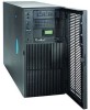
Panel Kit Install Guide: Intel® Entry Server Chassis SC5275-E UP/DP/WS/BRP Intel® Entry Server Chassis SC5299-E DP/WS/BRP Intel® Server Chassis SC5300 Intel® Server Chassis SC5400 A Guide for Technically Qualified Assemblers of Intel® Identified Subassemblies/Products Intel Order Number: C77420 - Intel SC5300BASE | Installation Guide - Page 2
for their specific application and environmental conditions. Intel Corporation can not be held responsible if components fail or the server board does not operate correctly when used outside any of their published operating or non-operating limits. Intel, Intel Pentium, and Intel Xeon are trademarks - Intel SC5300BASE | Installation Guide - Page 3
in this document before performing any of the instructions. See also Intel Server Boards and Server Chassis Safety Information on the Intel® Server Deployment Toolkit CD and/or at http://support.intel.com/support/ motherboards/server/sb/cs-010770.htm. Wichtige Sicherheitshinweise Lesen Sie - Intel SC5300BASE | Installation Guide - Page 4
Safety Information Warnings Heed safety instructions: Before working with your server product, whether you are using this guide or any other resource as a reference, pay close attention to the safety instructions. You must adhere to the assembly instructions in this guide to ensure and maintain - Intel SC5300BASE | Installation Guide - Page 5
System References ...2 Installation Instructions for Intel® Server Chassis SC5300/SC5400 2 Remove Access Cover Drive Bay of Server Chassis 14 Connect LCP Cable to LCP Header on Server Board 16 Replace Bezel ...17 Replace Access Cover ...18 Installation Instructions for Intel® Entry Server Chassis - Intel SC5300BASE | Installation Guide - Page 6
Contents Replace Bezel ...24 Replace Access Cover ...25 vi Local Control Panel Kit Install Guide - Intel SC5300BASE | Installation Guide - Page 7
on LCP Carrier 14 Figure 19. Installing Drive Rails to LCP Carrier 14 Figure 20. Inserting LCP Carrier into Drive Bay 15 Figure 21. Routing LCP Cable in Intel® Entry Server Chassis SC5275-E 15 Figure 22. Attaching LCP Cable to Header on Intel® Server Board SE7520AF2 16 Figure 23. Attaching LCP - Intel SC5300BASE | Installation Guide - Page 8
List of Figures viii Local Control Panel Kit Install Guide - Intel SC5300BASE | Installation Guide - Page 9
1 Local Control Panel Kit Installation Instructions Use the instructions in this installation guide to install a Local Control Panel display on an Intel® Server Chassis SC5300, Intel® Server Chassis SC5400, Intel® Entry Server Board SC5275-E or Intel® Entry Server Chassis SC5299-E. Note: For the - Intel SC5300BASE | Installation Guide - Page 10
Local Control Panel kit installations for the Intel® Server Chassis SC5300/SC5400. If you are installing a Local Control Panel kit into an Intel® Entry Server Chassis SC5275-E, follow the instructions under "Installation Instructions for Intel® Entry Server Chassis SC5275-E" on page 12. If you are - Intel SC5300BASE | Installation Guide - Page 11
Kit Installation Instructions Remove Bezel the bezel assembly away from the chassis (see letter "C"). If the bezel assembly does not immediately disconnect from the chassis then tap the left-hand bezel hooks on the right-hand side of the chassis. Caution: Do not rotate the bezel assembly more than - Intel SC5300BASE | Installation Guide - Page 12
Kit Installation Instructions Remove Outer Bezel Door from Bezel Assembly Note: The bezel assembly consists of two parts, an inner bezel door and an outer bezel door. With one hand supporting the inner bezel 3. Removing Outer Bezel Door from Bezel Assembly 4 Local Control Panel Kit Install Guide - Intel SC5300BASE | Installation Guide - Page 13
Local Control Panel Kit Installation Instructions Remove Upper Third of Bezel Grill Remove the upper one-third of the bezel grill by pushing grill forward. TP00636 bezel door by pressing grill in from the front. TP00637 Figure 5. Installing LCP Grill Local Control Panel Kit Install Guide 5 - Intel SC5300BASE | Installation Guide - Page 14
Kit Installation Instructions Remove Lowest CD-ROM/DVD Drive Filler Panel Remove the lowest CD-ROM/DVD/Floppy drive or filler panel from chassis. TP00638 Note:Removal of CD-ROM drive shown. Figure 6. Removing Lowest Floppy/CD-ROM/DVD Drives or Filler Panel 6 Local Control Panel Kit Install Guide - Intel SC5300BASE | Installation Guide - Page 15
Local Control Panel Kit Installation Instructions Install EMI Shield onto LCP Carrier Your backplane board shipped with an EMI shield EMI Shield on LCP Carrier Inserting LCP Carrier into Drive Bay of Server Chassis 1. Attach drive rails to LCP carrier using the top set of holes. TP00634 Figure - Intel SC5300BASE | Installation Guide - Page 16
Installation Instructions 2. Feed the LCP cable through the drive bay opening. Slide LCP carrier into server chassis. Make sure that the drive rails are using the correct slots in the chassis. Figure 9. Installing LCP Carrier TP00639 Route LCP Cable Route the LCP cable under the chassis fan area - Intel SC5300BASE | Installation Guide - Page 17
Kit Installation Instructions Connect LCP Cable to LCP Header of Server Board 1. Connect the LCP cable to the LCP header on the server board. 2. For an Intel Server Board SE7520AF2, use header J1J1 on the server board. TP00642 Figure 11. Attaching LCP Cable to Header on Intel® Server Board SE7520AF2 - Intel SC5300BASE | Installation Guide - Page 18
Installation Instructions 3. For an Intel Server Board SE7520BD2, use header J2K8 on the server board. TP00641 Figure 12. Attaching LCP Cable to Header on Intel® Server Board SE7520BD2 Replace Bezel Assembly Fit the right-hand side of the inner bezel door against the right-hand side of chassis and - Intel SC5300BASE | Installation Guide - Page 19
Local Control Panel Kit Installation Instructions Caution: Do not attach inner bezel door to chassis at more than a 40-degree angle Door Replace Access Cover Replace access cover and slide forward to secure cover to chassis. Replace shipping screw (see letter "A" in the following figure) if desired. - Intel SC5300BASE | Installation Guide - Page 20
Intel® Entry Server Chassis SC5275-E. If you are installing a Local Control Panel kit into an Intel® Server Chassis SC5300/SC5400, follow the instructions under "Installation Instructions for Intel® Server Chassis SC5300 Figure 15. Removing Access Cover 12 Local Control Panel Kit Install Guide - Intel SC5300BASE | Installation Guide - Page 21
attach the right side of the bezel to the chassis and remove (see letter "C"). Figure 16. Removing Bezel Remove Lowest CD-ROM/DVD Drive Filler Panel Remove the lowest CD-ROM/DVD/floppy drive or filler panel from chassis. Note:Removal of CD-ROM drive shown. Figure 17. Removing Lowest Floppy/CD-ROM - Intel SC5300BASE | Installation Guide - Page 22
Control Panel Kit Installation Instructions Install EMI Shield onto LCP Carrier Your backplane board shipped with Figure 18. Installing EMI Shield on LCP Carrier Inserting LCP Carrier into Drive Bay of Server Chassis 1. Install the drive rails by attaching each rail with two screws to the two lower - Intel SC5300BASE | Installation Guide - Page 23
Drive Bay Route LCP Cable Route the LCP cable to the corner of the server board where the LCP header is located on your Intel® Server Board SE7520AF2 or Intel® Server Board SE7520BD2. TP00646 Figure 21. Routing LCP Cable in Intel® Entry Server Chassis SC5275-E Local Control Panel Kit Install Guide - Intel SC5300BASE | Installation Guide - Page 24
Installation Instructions Connect LCP Cable to LCP Header on Server Board 1. Connect the LCP cable to the LCP header on the server board. 2. For an Intel® Server Board SE7520AF2, use header J1J1 on the server board. TP00648 Figure 22. Attaching LCP Cable to Header on Intel® Server Board SE7520AF2 - Intel SC5300BASE | Installation Guide - Page 25
Instructions 3. For an Intel® Server Board SE7520BD2, use header J2K8 on the server board. TP00647 Figure 23. Attaching LCP Cable to Header on Intel® Server right side of the chassis. 3. Rotate the left side of bezel towards the chassis (see letter "B"). Local Control Panel Kit Install Guide 17 - Intel SC5300BASE | Installation Guide - Page 26
Instructions 4. Snap the two bezel tabs (see letter "C") into their corresponding recesses at left edge of chassis. Figure 24. Installing Bezel Replace Access Cover To replace the access cover: 1. Position access cover on chassis see letter "C"). Caution: This chassis must be operated with the - Intel SC5300BASE | Installation Guide - Page 27
Intel® Entry Server Chassis SC5299-E. If you are installing a Local Control Panel kit into an Intel® Server Chassis SC5300/SC5400, follow the instructions in "Installation Instructions for Intel® Server Chassis SC5300 the following figure) from the chassis. Local Control Panel Kit Install Guide 19 - Intel SC5300BASE | Installation Guide - Page 28
Kit Installation Instructions 2. Rotate the left side of bezel outward slightly (see letter "B"). 3. Disengage the latches that attach the right side of the bezel to the chassis and remove (see letter "C"). C A C C A B TP02034 Figure 27. Removing Bezel Remove Lowest CD-ROM/DVD Drive Filler Panel - Intel SC5300BASE | Installation Guide - Page 29
Local Control Panel Kit Installation Instructions Install EMI Shield onto LCP Carrier Your backplane board shipped with an EMI shield that has to be installed. Install the EMI shield by carrier. A TP00635 Figure 29. Installing EMI Shield on LCP Carrier Local Control Panel Kit Install Guide 21 - Intel SC5300BASE | Installation Guide - Page 30
Local Control Panel Kit Installation Instructions Inserting LCP Carrier into Drive Bay of Server Chassis Slide the LCP carrier into the desired 5.25-in drive bay. Feed the cable in first. AF00567 Figure 30. Inserting LCP Carrier into Drive Bay Route LCP Cable Route the LCP cable to the corner of - Intel SC5300BASE | Installation Guide - Page 31
Header on Intel® Server Board S5000VSA 3. For an Intel® Server Board S5000PSL or Intel® Server Board S5000XVN, use header J2J1 on the server board. AF00570 Figure 33. Attaching LCP Cable to Header on Intel® Server Board S5000PSL or Intel® Server Board XVN Local Control Panel Kit Install Guide 23 - Intel SC5300BASE | Installation Guide - Page 32
Instructions Replace Bezel 1. If necessary, remove filler panel from bezel that corresponds to the position of the LCP carrier. 2. Line up the three clips (see letter "A" in the following figure) at the right edge of the bezel with the corresponding latches on the right side of the chassis - Intel SC5300BASE | Installation Guide - Page 33
Control Panel Kit Installation Instructions Replace Access Cover To replace the access cover: 1. Slide the access cover on the chassis and latch securely (see letter "A" in the following figure). 2. (optional) Replace shipping screws (see letter "B"). Caution: This chassis must be operated with - Intel SC5300BASE | Installation Guide - Page 34
Local Control Panel Kit Installation Instructions 26 Local Control Panel Kit Install Guide
-
 1
1 -
 2
2 -
 3
3 -
 4
4 -
 5
5 -
 6
6 -
 7
7 -
8
-
9
-
10
-
11
-
12
-
13
-
14
-
15
-
16
-
17
-
18
-
19
-
20
-
21
-
22
-
23
-
24
-
25
-
26
-
27
-
28
-
29
-
30
-
31
-
32
-
33
-
34
 |
 |

Local Control Panel Kit Install Guide:
Intel® Entry Server Chassis SC5275-E
UP/DP/WS/BRP
Intel® Entry Server Chassis SC5299-E
DP/WS/BRP
Intel® Server Chassis SC5300
Intel® Server Chassis SC5400
A Guide for Technically Qualified Assemblers of Intel
®
Identified Subassemblies/Products
Intel Order Number: C77420-002