Intel SC5650BRP Quick Start Guide
Intel SC5650BRP - Server Chassis - Tower Manual
 |
UPC - 735858207409
View all Intel SC5650BRP manuals
Add to My Manuals
Save this manual to your list of manuals |
Intel SC5650BRP manual content summary:
- Intel SC5650BRP | Quick Start Guide - Page 1
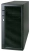
Intel® Server Chassis SC5650BRP/SC5650DP/ SC5650WS/SC5650UP Quick Start User's Guide Thank you for buying the Intel® Server Chassis SC5650. The following information will help you to prepare your chassis for integration with your selected Intel® Server Board. These guides and other supporting
-
 1
1
 |
 |

Thank you for buying the Intel
®
Server Chassis SC5650.
The following information will help you to prepare your chassis
for integration with your selected Intel
®
Server Board.
These guides and other supporting documents (including
a list of supported server boards) are located on the web at
If you are not familiar with ESD (Electrostatic Discharge) procedures
used during system integration, please see the Intel
®
Server
Chassis SC5650 Service Guide, available on the CD that came with
your Intel® Server Board.
Read all cautions and warnings before starting your server chassis
integration.
Intel
®
Server Chassis
SC5650BRP/SC5650DP/
SC5650WS/SC5650UP
Quick Start User's Guide
Building Value With Intel
Server Products, Programs and Support
Get the high-value server solutions you need by
taking advantage of the outstanding value Intel
provides to system integrators:
•
High-quality server building blocks
•
Extensive breadth of server building blocks
•
Solutions and tools to enable e-Business
•
Intel
®
System Management Software
•
Comprehensive training services
•
Worldwide 24x7 technical support
[AT&T Country Code + 866-655-6565]
1
•
World-class service, including a three-year
limited warranty and Advanced Warranty
Replacement
1
•
Product information, including product
briefs and technical product
specifications
•
Sales tools, such as videos and
presentations
•
Training information, such as the Intel
®
Online Learning Center
•
Support Information and much more
Intel
®
ServerBuilder is your one-stop shop
for information about all of Intel's server
building blocks, such as:
1
Available only to Intel
®
Channel Program
Members, part of the Intel
®
e-Business Network.
7
Install Server Board
6
Remove PCI Card Guide
(only for S5500BC)
1
2
Press in on two blue tabs.
1
Pull PCI card guide outward and remove
from chassis.
2
3
Remove Tool-less Hard Drive Cage
3
2
2
1
2
Push blue plastic
release mechanism
upward to unlatch
hard drive cage.
1
Loosen thumb screw. Apply pressure
to right side of EMI shield to release
EMI shield from hard drive cage.
Once released, pull hard drive
cage out of chassis.
3
4
Install Tool-less CD-ROM or DVD-ROM Drive
1
2
3
2
1
Remove EMI shield from 5.25-inch device drive bay.
Make sure latch is in "unlock" position.
Line up holes in CD-ROM
or DVD-ROM drive with
holes in chassis.
Connect power (P5 or P6 for
DP/BRP/WS; P3 or P4 for UP)
cables and data cables to rear
of the CD-ROM or DVD-ROM
drive.
Move latch to "lock" position.
Insert CD-ROM or DVD-ROM
drive into device drive bay.
An additional 4-pin IDE male-to-SATA 15 pin power cable
adapter may be needed if the CD-ROM or DVD-ROM does
not have a 4-pin power connector.
6
5
4
Data cables are included with the Intel
®
Server Board.
3
5
4
6
Data
Power
Use the mounting screws, bumpers and standoffs (if necessary) that came
with your chassis to secure the server board to the chassis.
For other configurations, see the
Quick Start User's Guide
that came
with your Intel
®
Server Board.
Return to this document when finished.
See your Intel
®
server board
Quick Start User's Guide
for server board
installation instructions and installation of the back panel I/O shield.
The standoffs that ship with the chassis need to be adjusted to
accommodate the Intel
®
Server Board
assembled.
For the Intel
®
Server Board S5500BC, standoffs should be installed at the following
positions:
K, L, M, F, 3, H, A and C.
For the Intel
®
Server Board
S5520HC/S5500HCV/S5520SC, standoffs should be installed at the
following positions:
K, L1, F, 3, E, J1, A, C and D, while there is a
push pin already installed at position N.
For the
Intel
®
Server Board S3420GP family, standoffs should be
installed at the following positions: 1,3,A,C,F,H,K,L and M.
Intel is a registered trademark of Intel Corporation or its
subsidiaries in the United States and other countries.
*Other names and brands may be claimed as the
property of others.
Copyright © 2009, Intel Corporation.
All rights reserved.
Warning
Read all caution and safety
statements in this document
before performing any of the
instructions.
Also see the
Intel
®
Server Board and Server Chassis
Safety Information
document at:
motherboards/server/sb/cs-010770
.htm
for complete safety information.
Warning
Installation and service of
this product to be performed
only by qualified service
personnel to avoid risk of injury from
electrical shock or energy hazard.
Tools Required
Caution
Observe normal ESD
[Electrostatic Discharge]
procedures during system
integration to avoid possible
damage to server board and/or
other components.
Anti-static
wrist strap
#2 Phillips*
screwdriver
E39540-004
Hex nut driver
(0.25 in or
6 mm)
5
a
Remove Fan Duct/
System Fan Assembly
For SC5650 DP/BRP/WS only:
Remove fan duct assembly as shown.
1
Remove system fan by
pushing the right and
left tabs outward and
disengaging from
fan housing.
2
1
2
Right
Tab
Left
Tab
Intel® Server Board Guide
Compatible
Intel
®
Server Board
Chassis Configuration
Product Code
S5520SC
S5500BC, S5520HC,
S5500HCV
SC5650WS
SC5650BRP
SC5650DP
S5500BC, S5520HC,
S5500HCV
SC5650DP and SC5650BRP do not need a system air duct with S5500BC board.
Only SC5650WS can support 130 W TDP CPU.
The server board that can be installed in your
Intel
®
Server Chassis SC5650 is dependent upon
the configuration of the chassis purchased.
SC5650UP
S3420GP Family
1
Remove Side Cover
1
2
Remove two screws.
Push in latch.
3
Slide side cover
rearward and remove.
2
3
1
1
2
Remove Front Bezel Assembly
3
Disengage three bezel clips
that attach the right side
of the bezel to the right side of
the chassis and remove.
2
Rotate left side of front bezel
assembly outward slightly.
1
Lift outward two bezel tabs on
left side of bezel assembly
to detach bezel assembly from
the chassis.
2
3
1
1
3
3
Intel
®
Server
Chassis SC5650DP
✓
= Fan header used
Intel
®
Server
Chassis SC5650BRP
Notes:
System Fan
1
✓
✓
PCI Zone Chassis Fan
System Fan
2
✓
✓
HDD Cage Fan
System Fan
3
✓
✓
Rear Chassis Fan
Chassis Fan Connection for the Intel
®
Server Board S5500BC
Intel
®
Server
Chassis SC5650DP
✓
= System Fan
header used
Intel
®
Server
Chassis SC5650BRP
Intel
®
Server
Chassis SC5650WS
Notes:
System Fan
1
✓
✓
PCI Zone Chassis Fan
System Fan
2
System Fan
3
✓
✓
✓
✓
System Fan
4
System Fan
5
✓
✓
✓
HDD Cage Fan
Rear Chassis Fan
Chassis Fan Connection for the Intel
®
Server Boards S5520HC / S5500HCV and Intel
®
Workstation Board S5520SC
S5520HC/S5500HCV
S5520SC
✓
✓
✓
Intel
®
Server
Chassis SC5650UP
✓
= Fan header used
Notes:
System Fan
1
System Fan
2
✓
HDD Cage Fan
System Fan
3
System Fan
4
✓
Rear Chassis Fan
Chassis Fan Connection for the Intel
®
Server Board S3420GP Family
5
b
Remove Fan Duct/System Fan
Assembly (for UP)
For SC5650UP only,
remove fan duct
assembly and system
fan by pushing the left
and right tabs outward
and disengaging from snap-in bracket.
1
Snap-in
Bracket