Intel SDS2 Product Specification
Intel SDS2 Manual
 |
View all Intel SDS2 manuals
Add to My Manuals
Save this manual to your list of manuals |
Intel SDS2 manual content summary:
- Intel SDS2 | Product Specification - Page 1
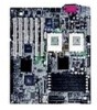
Intel® Server Board SDS2 Technical Product Specification Order Number: A85874-002 Revision 1.2 December 2, 2002 Enterprise Platforms and Services Marketing - Intel SDS2 | Product Specification - Page 2
History Revision History Intel® Server Board SDS2 Date 9/20/2001 5/15/2002 12/2/02 Revision Number 1.0 1.1 1.2 Modifications Initial release. Added Section 13: Errata. Corrected miscellaneous document errors. Added Table 6.2.5.4: Baseboard Management Controller (BMC) Beep Code Generation. Added - Intel SDS2 | Product Specification - Page 3
any features or instructions marked "reserved" or "undefined." Intel reserves these for local sales office that you have the latest datasheet before finalizing a design. The Intel® Server Board SDS2 the license. The information in this manual is furnished for informational use only, is subject to - Intel SDS2 | Product Specification - Page 4
Table of Contents Intel® Server Board SDS2 Table of Contents 1. Introduction ...1 2. Architecture ...2 3. Processor and Chipset ...4 3.1 Processors ...4 3.1.1 Processor Voltage Regulator Module (VRM 6 3.2 Memory Subsystem...6 3.2.1 Memory Configuration 6 3.2.2 I2C Bus ...8 3.3 Chipset...8 3.3.1 - Intel SDS2 | Product Specification - Page 5
Intel® Server Board SDS2 Table of Contents 4.6.2 BIOS Flash...20 4.7 Interrupt Routing ...20 4.7.1 Legacy Interrupt Routing 20 4.7.2 APIC Interrupt Routing 21 4.7.3 Serialized IRQ Support 21 4.7.4 IRQ Scan for PCIIRQ 21 5. Server Management...25 5.1 Sahalee Baseboard Management Controller 27 - Intel SDS2 | Product Specification - Page 6
Table of Contents Intel® Server Board SDS2 6.3.4 Clearing CMOS...67 6.4 Flash Update Utility ...67 6.4.1 Loading the System BIOS 67 6.4.2 User Binary Area...68 6.4.3 Language Area...68 6.4.4 OEM Logo Screen ...68 6.4.5 Recovery Mode ...68 7. Clock/Voltage Generation and Distribution 70 7.1 Clock - Intel SDS2 | Product Specification - Page 7
Intel® Server Board SDS2 Table of Contents 8.9 Connector Manufacturers and Part Numbers 87 9. Jumpers...88 9.1 System Configuration Jumpers 88 9.2 Performing CMOS Clear, BIOS Recovery, and BMC Force Update 92 9.2.1 Performing CMOS Clear 92 9.2.2 Performing BIOS Recovery Boot 92 9.2.3 - Intel SDS2 | Product Specification - Page 8
Intel® Server Board SDS2 5. Intel® & ICP Vortex* RAID Controllers will cause the Intel® Server Board SDS2 to halt during POST when the BIOS Logo screen is enabled 109 6. Intel® Server Board SDS2 CD-ROM issues 110 7. NIC driver memory is installed 124 viii Revision 1.2 Order Number: A85874-002 - Intel SDS2 | Product Specification - Page 9
Intel® Server Board SDS2 Table of Contents 34. Peer-to-peer PCI transactions are not supported between the CIOB-controlled 64-bit PCI bus and the legacy 32-bit PCI bus controlled by the HE-SL north bridge 125 35. SDS2 PCI slot current levels supported by the 5V rail 125 36. OB P100 NICs do not - Intel SDS2 | Product Specification - Page 10
List of Figures Intel® Server Board SDS2 List of Figures Figure 1. SDS2 Server Board Block Diagram 1 Figure 2. SDS2 Memory Bank Layout 7 Figure 3. SDS2 Interrupt Routing Diagram (CSB5 Internal 22 Figure 4. SDS2 Interrupt Routing Diagram 23 Figure 5. SDS2 PCI Interrupt Mapping Diagram 24 - Intel SDS2 | Product Specification - Page 11
Intel® Server Board SDS2 List of Tables List of Tables Table 1. SDS2 Intel® Pentium® III Processor Support Matrix 4 Table 2. Memory DIMM Pairs ...7 Table 3. I2C Addresses for DIMM Slots 8 Table 4. PCI Bus Segment Characteristics 11 Table 5. P32-A Configuration IDs 12 Table 6. P32-A - Intel SDS2 | Product Specification - Page 12
Intel® Server Board SDS2 Table 32. Main Menu Selections ...55 Table 33. Primary Master and Slave IDE Submenu Selections 56 Table 34. Processor Settings Submenu Selections 57 Table 35. Advanced Menu Selections 58 Table 36. Memory Connector Pin-out 81 xii Revision 1.2 Order Number: A85874-002 - Intel SDS2 | Product Specification - Page 13
Intel® Server Board SDS2 Part Numbers 87 Table 78. System Configuration Jumper Options 91 Table 79. CPU Frequency Select Jumper Options 91 Table 80. List of Assembled Jumpers in Production 92 Table 81. Absolute Maximum Ratings 94 Table 82. SDS2 Server Board Power Consumption 95 Table 83: SDS2 - Intel SDS2 | Product Specification - Page 14
List of Tables Intel® Server Board SDS2 < This page intentionally left blank. > xiv Revision 1.2 Order Number: A85874-002 - Intel SDS2 | Product Specification - Page 15
Intel® SDS2 Server Board. It provides a view of the functional blocks and their electrical relationships. The figure below shows the functional blocks of the Server Board and the plug-in modules that it supports B Figure 1. SDS2 Server Board Block Diagram Revision 1.2 1 Order Number: A85874-002 - Intel SDS2 | Product Specification - Page 16
PC-133 compliant Registered SDRAM memory modules are supported. The current tested memory listing is posted on the Intel technical support web site: http://support.intel.com/support/motherboards/server/SDS2/ The SDS2 Server Board provides the following features: • Dual Intel® Pentium® III FCPGA2 - Intel SDS2 | Product Specification - Page 17
Intel® Server Board SDS2 Architecture • 64-bit, 66-MHz 3.3 V full-length PCI segment C (P64-C) device for system BIOS: Fairchild* 29LV008B 8Mbit Flash ROM • Two IDE connectors, supporting up to two ATA-100 compatible devices each. Note: Fab 4 board PBA A58285-402 and -403 supported only one IDE - Intel SDS2 | Product Specification - Page 18
Server Board directly supports up to 6 GB of ECC memory, using six PC-133compliant registered SDRAM DIMMs. The ECC implementation in the HE-SL can detect and correct single-bit errors, and it can detect multiple-bit errors. 3.1 Processors The SDS2 Server Board supports two Intel S-Spec N/A Supported - Intel SDS2 | Product Specification - Page 19
FAB 5) supports the tB1 stepping, CPUID 06B4. These processors are being evaluated for addition to supported processor list. The current Intel support web site has the latest supported processor list for SDS2: http://support.intel.com/support/motherboards/server/SDS2/. Revision 1.2 5 Order Number - Intel SDS2 | Product Specification - Page 20
not identical, then the BMC will not turn on the VRMs and a beep code is generated. Table 30. BMC Beep Codes lists all of the error codes. 3.2 Memory Subsystem The SDS2 Server Board supports up to six DIMM sockets for a maximum memory capacity of 6 GB using 1 GB DIMMs. The DIMM organization is x72 - Intel SDS2 | Product Specification - Page 21
Intel® Server Board SDS2 Table 2. Memory DIMM Pairs Memory DIMM DIMM1A, DIMM1B DIMM2A, DIMM2B DIMM3A, DIMM3B DIMM PAIR 1 2 3 Row 1, 2 3, 4 5, 6 Processor and Chipset DIMM Pair 1 DIMM Pair 2 DIMM Pair 3 Figure 2. SDS2 Memory Bank Layout Revision 1.2 7 Order Number: A85874-002 - Intel SDS2 | Product Specification - Page 22
Intel® Server Board SDS2 3.2.2 I2C Bus An I2C* bus is between the BMC and the six DIMM slots. This bus is used by the system BIOS to retrieve DIMM information needed to program the HE-SL memory a number of GPIO pins and has the LPC bus to support low-speed legacy I/O. 8 Revision 1.2 Order - Intel SDS2 | Product Specification - Page 23
Intel® Server Board SDS2 Processor and Chipset 3.3.1 CNB20HE-SL Champion North Bridge The Champion North Bridge Rev 2.0 High End Super Lite (CNB20HE-SL) is the third generation product in the Server Works Champion North Bridge Technology. The HE-SL is a 644-pin ballgrid array (BGA) device and - Intel SDS2 | Product Specification - Page 24
Intel® Server Board SDS2 3.3.2 CIOB20 Champion I/O Bridge The Champion I/O Bridge (CIOB) is a 352-pin ball-grid array device and provides an integrated I/O bridge that provides a high-performance data flow path between the IMBus and the 64-bit I/O subsystem. This subsystem supports support supports - Intel SDS2 | Product Specification - Page 25
Intel® Server Board SDS2 I/O Subsystem 4. I/O Subsystem 4.1 PCI Subsystem The primary I/O bus for SDS2 DP Server Board is PCI, SDS2 Server Board is directed through the HE-SL North Bridge. The 32-bit, 33-MHz PCI segment created by the HE-SL is called the P32-A segment. The P32-A segment supports - Intel SDS2 | Product Specification - Page 26
Subsystem Intel® Server Board SDS2 Table 5. P32-A Configuration IDs IDSEL Value 18 19 20 24 25 31 Device ATI RAGE XL Video Controller Intel® 82550 Fast Ethernet Controller 1 Intel 82550 Fast Ethernet Controller 2 PCI Slot 3 PCI Slot 4 CSB5 South Bridge 4.1.1.2 P32-A Arbitration P32-A supports - Intel SDS2 | Product Specification - Page 27
Intel® Server Board SDS2 Table 4. P64-B Configuration IDs IDSEL Value 24 25 Device PCI Slot 1 PCI Slot 2 I/O Subsystem Table 5. P64-C Configuration IDs IDSEL Value 20 24 25 Device Adaptec AIC-7899W SCSI Controller PCI Slot 5 PCI Slot 6 4.1.2.2 P64-B Arbitration P64-B supports three PCI - Intel SDS2 | Product Specification - Page 28
Intel® Server Board SDS2 4.1.2.4 Zero Channel RAID (ZCR) Capable PCI Slot 6 The SDS2 Server Board supports zero-channel RAID controller on PCI Slot 6. This add-in card leverages the on-board MB SDRAM chips provide 4 MB of video memory. The SVGA subsystem supports a variety of modes, up to 1024 x - Intel SDS2 | Product Specification - Page 29
's baseline functionality is equivalent to that of the Intel 82559 with the addition of Alert on LAN* functionality. The SDS2 Server Board supports independent disabling of either of the two NIC controllers under BIOS setup menu. The 82550 supports the following features: • 32-bit PCI/Card Bus - Intel SDS2 | Product Specification - Page 30
Subsystem Intel® Server Board SDS2 4.4.1 SDS2 Server Board supports two IDE channels through the standard 40-pin (2x20) connector. Note FAB 4 boards (PBA A58285-402 and -403) supported only one IDE channel. The SDS2 IDE interface supports the following features: 16 Revision 1.2 Order Number - Intel SDS2 | Product Specification - Page 31
Intel® Server Board SDS2 I/O Subsystem • The scatter / gather mechanism supports both DMA and PIO IDE drives and ATAPI devices • Support for ATA and ATAPI, PIO Mode 0, 1, 2, 3, 4, DMA errors on Front Side Data bus and Memory Data bus Reporting for errors from CIOB Generation of NMI from CSB5 - Intel SDS2 | Product Specification - Page 32
Intel® Server Board SDS2 from jumper to be in BIOS Recovery mode in case of , and PS/2-compatible keyboard and mouse. The SDS2 Server Board supports the following features: • GPIO • Two serial Super I/O provides number of general-purpose input/output pins that the SDS2 Server Board utilizes. The - Intel SDS2 | Product Specification - Page 33
Intel® Server Board SDS2 I/O Subsystem Pin # 35 36 37 stacked over the keyboard connector. 4.6.1.5 Parallel Port The parallel port is supported on the Server Board through the rear I/O. 4.6.1.6 Real-time Clock The SIO contains a off of the system. Revision 1.2 19 Order Number: A85874-002 - Intel SDS2 | Product Specification - Page 34
Intel® Server Board SDS2 4.6.2 BIOS Flash The SDS2 Server Board incorporates a Fairchild* 29LV008B 8Mbit Flash ROM. The flash device is connected through the X-bus of the CSB5. 4.7 Interrupt Routing The SDS2 Server Board servicing these to the APIC bus. The numbers in the table below indicate the - Intel SDS2 | Product Specification - Page 35
APIC Interrupt Routing For APIC mode, the SDS2 interrupt architecture incorporates three Intel I/O APIC devices to manage and broadcast interrupts SDS2 Server Board has an external PCI interrupt serializer for PCIIRQ scan mechanism of CSB5 to support 16 PCIIRQs. Revision 1.2 21 Order Number - Intel SDS2 | Product Specification - Page 36
I/O Subsystem Intel® Server Board SDS2 IRQ0 IRQ1 IRQ2 IRQ3 IRQ4 IRQ5 IRQ6 IRQ7 IRQ8 IRQ9 IRQ10 IRQ11 IRQ12 IOAPIC 2 MASK for PCIIRQ16-31 1 PCIIRQ16 PCI Cycle 8259 PIC PCIIRQ to IRQ MAPPING Figure 3. SDS2 Interrupt Routing Diagram (CSB5 Internal) 22 Revision 1.2 Order Number: A85874-002 - Intel SDS2 | Product Specification - Page 37
Intel® Server Board SDS2 Timer Super I/O Keyboard Cascade Serial Port2/ISA Serial Port1/ISA ISA Floppy/ISA PCI IRQ Serializer SERIRQ PCI Clock 33 MHz PIRQ1 PIRQ_LATCH Figure 4. SDS2 Interrupt Routing Diagram Revision 1.2 Order Number: A85874-002 CSB5 Interrupt Routing I/O Subsystem 23 - Intel SDS2 | Product Specification - Page 38
I/O Subsystem Intel® Server Board SDS2 Slot 6 Slot 5 Slot 4 Slot 3 Slot 2 Slot 1 INTA INTB INTC INTD PCI IRQ 10 PCI IRQ 9 PCI IRQ 8 PCI IRQ 7 PCI IRQ 6 PCI IRQ 5 PCI IRQ 13 PCI IRQ 11 PCI IRQ 12 SCSI PORT A PORT B ZCR Present NIC 1 NIC 2 VIDEO Figure 5. SDS2 PCI Interrupt Mapping - Intel SDS2 | Product Specification - Page 39
Intel® Server Board SDS2 Server Management 5. Server Management The SDS2 server management features are implemented using the Sahalee Server Board Management the SDS2 server management architecture. A description of the hardware architecture follows. Revision 1.2 25 Order Number: A85874-002 - Intel SDS2 | Product Specification - Page 40
Server Management Intel® Server Board SDS2 Chassis Intrusion Front Panel NMI Switch Sleep Button System Identify Button Reset Button Power Button Fault Status LED Drive Activity/Fault LED Identify LED Power - Intel SDS2 | Product Specification - Page 41
Intel® Server Board SDS2 Server Management 5.1 Sahalee Baseboard Management Controller The Sahalee BMC contains a 32-bit RISC processor core and associated VID[2] CPU1 VID[3] CPU1 VID[4] CPU1 Thermal Trip CPU2 Thermal Trip Chassis Intrusion Description Revision 1.2 27 Order Number: A85874-002 - Intel SDS2 | Product Specification - Page 42
37 N_SC2VREF2+00 38 N_SC2VREF1+00 39 N_SC1VREF3+00 40 N_SC1VREF2+00 41 N_SC1VREF1+00 Intel® Server Board SDS2 Description Serial Bus Clock Serial Bus Data Pulse-width modulated output for control of fan Front System Fan 2 Speed Rear System Fan 1 Speed 28 Order Number: A85874-002 Revision 1.2 - Intel SDS2 | Product Specification - Page 43
Intel® Server Board SDS2 Pin Signal Name C14 N_FAN6_SENSE_P L12 N_MEM_ALERT_L M12 N_BMC_SECUREMODE Description Rear System Fan 2 Speed Memory ECC Error Detect Secure Mode Detect Server Management Note: For a complete listing of BMC sensors, please refer to SDS2 Baseboard Management - Intel SDS2 | Product Specification - Page 44
Server Management Intel® Server Board SDS2 5.2 System Reset Control Reset circuitry on the SDS2 Server Board looks at Server Board and system chassis. An added layer in the protocol supports transactions between multiple servers on inter-chassis I2C bus segments. 30 Revision 1.2 Order Number - Intel SDS2 | Product Specification - Page 45
Intel® Server Board SDS2 Server Management Table 17. IPMB Bus Devices Function SCSI HSBP-A SCSI HSBP-B OEM Connector Voltage 5VSB 5VSB 5VSB Address 0xC0 0xC2 N/A Notes In addition to the "public" IPMB, the Sahalee BMC also has five private I2C busses. Four of these are used on the Server Intel - Intel SDS2 | Product Specification - Page 46
Address 0xC2 0xA0 0xA2 0xA4 0xA6 0xA8 0xAA 0xD2 South Bridge Clock Buffers Intel® Server Board SDS2 Notes Function NIC1 NIC2 Voltage 3 VSB 3VSB Table 21. Private I2C Bus by BIOS. 5.4.3 Intel® Pentium® III Processor Bus Errors The HE-SL supports all the data integrity features supported by - Intel SDS2 | Product Specification - Page 47
Intel® Server Board SDS2 Server Management uncorrectable errors. In addition, the HE-SL can generate BERR# on unrecoverable ECC errors detected on the processor bus. Unrecoverable errors are routed to NMI by BIOS. 5.4.4 Memory Bus Errors The HE-SL is programmed to generate an SMI on single-bit - Intel SDS2 | Product Specification - Page 48
Server Management Setup Utility (F2) can change the AC link mode settings. Intel® Server Board SDS2 34 Revision 1.2 Order Number: A85874-002 - Intel SDS2 | Product Specification - Page 49
software for the SDS2 server board. The BIOS contains standard PC-compatible basic input/output (I/O) services, system-specific hardware configuration routines and register default settings that are embedded in Flash read-only memory (ROM). This document also describes BIOS support utilities (not - Intel SDS2 | Product Specification - Page 50
BIOS Intel® Server Board SDS2 • OEM customization • PCI and Plug and Play (PnP) BIOS interface • Console redirection • Resource allocation support 6.2 BIOS Error Handling This section defines how errors are handled by the system BIOS on the SDS2 server board. Also discussed are the role of BIOS - Intel SDS2 | Product Specification - Page 51
Intel® Server Board SDS2 BIOS The BIOS logs the following SEL entries. Sensor Type Processor Memory POST Memory Resize POST Error Event Logging Disabled System Event Critical Interrupt System Boot Initiated Boot Error Sensor Failure Chipset Specific Critical Interrupt Table 22. BIOS Generated - Intel SDS2 | Product Specification - Page 52
BIOS Intel® Server Board SDS2 Table 23: Event Request Message Event Data Field Contents Event Trigger Class Discrete Event Data 7:6 00 = Unspecified byte 2 01 = Previous state and/or severity in byte 2 10 = OEM code in byte 2 11 = Sensor specific event extension code in byte 2 5:4 00 = - Intel SDS2 | Product Specification - Page 53
Intel® Server Board SDS2 BIOS 6.2.3.3 Memory Bus Error The BMC monitors and logs memory errors. The BIOS will configure the hardware to notify the BMC on correctable and uncorrectable memory -of-band interfaces. 6.2.4.1 Sensor Number and Types Codes The BIOS generates a POST error message when - Intel SDS2 | Product Specification - Page 54
BIOS 40 Intel® Server Board SDS2 Sensor # Sensor Name Sensor Type Event/ Reading Type Event Offset Triggers Lost POST error Front Panel NMI Correctable ECC, Uncorrectable ECC Correctable Memory Error Logging Disabled, Log Area Reset/Cleared - - - - - - Order Number: A85874-002 Revision 1.2 - Intel SDS2 | Product Specification - Page 55
Intel® Server Board SDS2 Sensor # Sensor Name Sensor Type Event/ Reading Type Event Offset Triggers BB -12V 10h Voltage - 02h BB - 06h Threshold 01h Threshold 01h Threshold 01h Threshold 01h Threshold 01h Threshold 01h Performance Lags - Revision 1.2 Order Number: A85874-002 BIOS 41 - Intel SDS2 | Product Specification - Page 56
BIOS Intel® Server Board SDS2 Sensor # Sensor Name Sensor Type Event/ Reading Type Event Offset Triggers Fan Boost Performance Lags Performance Lags Performance Lags Performance Lags Performance Lags Presence, Failure, Predictive Fail, A/C Lost 42 Revision 1.2 Order Number: A85874-002 - Intel SDS2 | Product Specification - Page 57
Intel® Server Board SDS2 Sensor # Sensor Name Sensor Type Event/ Reading Type Power Supply 2 5Bh Power Supply - Sensor 08h Specific - 6Fh Power Supply 3 5Ch Power Supply 08h Sensor Specific - 6Fh Missing CPU Module 5Eh Module/Board Revision 1.2 Order Number: A85874-002 BIOS 43 - Intel SDS2 | Product Specification - Page 58
BIOS Intel® Server Board SDS2 Sensor # Sensor Name Sensor Type Event/ Reading Type Event Offset Triggers DIMM 6 6Dh Slot when software asynchronously changes the value. In addition to this, the BIOS send a timestamp to the BMC using Set SEL Time command during POST. 44 Revision 1.2 Order - Intel SDS2 | Product Specification - Page 59
Intel® Server Board SDS2 BIOS 6.2.5 Error Messages and Error Codes The system BIOS displays error messages on the video screen. Before video initialization, beep codes inform the user of errors. POST error codes are logged in the System Event Log. The BIOS displays POST error codes on the video - Intel SDS2 | Product Specification - Page 60
BIOS Intel® Server Board SDS2 The following table contains the POST codes displayed during the boot process. A beep code is a series of individual beeps on the PC speaker, each of equal length. The following table describes the error conditions associated with each beep code and the corresponding - Intel SDS2 | Product Specification - Page 61
Intel® Server Board SDS2 BIOS CP Beeps BIOS stops execution here if the BIOS does not detect any usable memory DIMMs Initializes the POST Memory Manager Clear 8 MB base RAM Base RAM failure, BIOS stops execution here if entire memory BIOS video BIOS ROM Display copyright notice Allocate memory - Intel SDS2 | Product Specification - Page 62
hard disk controller 91 Initialize local bus hard disk controller 92 Jump to UserPatch2 93 Build MPTABLE for multi-processor boards 94 Disable A20 address line 95 Install CD-ROM for boot 96 Clear huge ES segment register 48 Order Number: A85874-002 Intel® Server Board SDS2 Revision 1.2 - Intel SDS2 | Product Specification - Page 63
Intel® Server Board SDS2 CP Beeps 97 98 1-2 99 9A 9C 9D 9E A0 A2 A4 Fix up Multi Processor table Reason Search for option ROMs. One long, two short beeps on checksum failure Check for SMART Drive Shadow option ROMs Set up Power Management Initialize security engine Enable hardware - Intel SDS2 | Product Specification - Page 64
BIOS Intel® Server Board SDS2 6.2.5.3 POST Error Codes and Messages The following table defines POST error codes and their associated messages. The BIOS type - run SETUP System cache error - Cache disabled System Memory exceeds the CPU's caching limit. EISA CMOS not write able Number: A85874-002 - Intel SDS2 | Product Specification - Page 65
Intel® Server Board SDS2 BIOS Code 0614 0615 0616 0617 0618 0619 061A 0B00 0B01 0B02 0B1B 0B1C 0B22 0B28 0B29 0B30 0B31 0B32 0B33 0B34 0B35 0B50 0B51 0B60 0B61 - Intel SDS2 | Product Specification - Page 66
BIOS Intel® Server Board SDS2 Code 1-5-1-1 1-5-2-1 1-5-2-2 1-5-2-3 1-5-4-2 1-5-4-3 1-5-4-4 Reason for Beep FRB failure (processor failure) to configure the platform. The Setup utility is part of the system BIOS and allows limited control over on-board resources such as parallel port and mouse. - Intel SDS2 | Product Specification - Page 67
Intel® Server Board SDS2 BIOS Options Menu Item Specific Help Screen Each Option Menu occupies the left and center sections privileges (or other reasons), the feature's value field is inaccessible. The Keyboard Command Bar supports the following: Revision 1.2 53 Order Number: A85874-002 - Intel SDS2 | Product Specification - Page 68
BIOS Intel® Server Board SDS2 Key F1 Enter ESC ↑ ↓ ↔ F9 Option Help Execute Command Exit Select Item Select Item Select Menu Setup Defaults Description user is returned to where they were before F10 was pressed without affecting any existing values. 54 Revision 1.2 Order Number: A85874-002 - Intel SDS2 | Product Specification - Page 69
Intel® Server Board SDS2 BIOS 6.3.2.3 Menu Selection Bar The Menu Selection Bar is located at the top of the screen. It displays the various major menu selections available to the user: • Main Menu. • Advanced Menu. • Security Menu. • Server Menu. • Boot Menu. • Exit Menu. These and associated - Intel SDS2 | Product Specification - Page 70
BIOS Feature Spanish Italian French German Option Intel® Server Board SDS2 Description Table 33. Primary Master is only available for Type User. This field is informational only, for Type Auto. Total number of sectors on the drive that are addressable in LBA format. Capacity of the drive while - Intel SDS2 | Product Specification - Page 71
Intel® Server Board SDS2 Feature Transfer Mode Ultra DMA Mode Option Standard FPIO 1 FPIO 2 FPIO 3 FPIO 4 FPIO 3 / DMA 1 FPIO 4 /DMA 2 Disabled Mode 0 Mode 1 Mode 2 Mode 3 Mode 4 Mode 5 BIOS Description Select the method for moving data to/from the drive. This field is informational only, for - Intel SDS2 | Product Specification - Page 72
BIOS Intel® Server Board SDS2 6.3.2.3.2 Advanced Menu Selections The following tables describe the menu options and associated submenus available on the Advanced Menu. Please note that MPS 1.4/1.1 selection is no longer configurable. The BIOS always builds MPS 1.4 tables. Table 35. Advanced - Intel SDS2 | Product Specification - Page 73
Intel® Server Board SDS2 Extended RAM Step Disabled 1 MB 1 KB Every- Location BIOS Selects the size of step to use during Extended RAM tests. Feature Embedded SCSI Embedded NIC 1 Embedded NIC 2 Embedded Video Controller PCI slot 1 PCI slot 2 - Intel SDS2 | Product Specification - Page 74
BIOS Feature Option ROM Scan Enabled Disabled Option Intel® Server Board SDS2 Description Enable option ROM scan of the selected device. 60 Revision 1.2 Order Number: A85874-002 - Intel SDS2 | Product Specification - Page 75
Intel® Server Board SDS2 BIOS Table 41. I/O Device/Peripheral Configuration Submenu Selections Feature Serial Port 1 Base I/O Address Interrupt Serial Port 2 Base I/O Address Interrupt Parallel Port Mode Base I/O Address Interrupt DMA channel Legacy USB support to "Auto," BIOS or configures the - Intel SDS2 | Product Specification - Page 76
BIOS Intel® Server Board SDS2 Table 42. Advanced Chipset Controller Submenu Selections Feature PCI Device Wake On Ring Wake On LAN Sleep Button Option Enabled Disabled Enabled Disabled Present Absent Description Selects sub-menu Only controls legacy wake up. May not be present if not supported. - Intel SDS2 | Product Specification - Page 77
Intel® Server Board SDS2 Enabled BIOS Description Server Menu Selections Option Description Selects sub-menu. Selects sub-menu. Displays the partition type of the Service Partition; the default is 12h. If selected, the System Event log will be cleared i m m ediately. Revision 1.2 63 Order Number - Intel SDS2 | Product Specification - Page 78
State Stay off Intel® Server Board SDS2 Description If enabled, BIOS Version Board Part Number Board Serial Number Sys tem Part Number System Serial Number Chassis Part Number Chassis Serial Number BMC Device ID BMC Device Revision BMC Firmware Revision BMC Firmware BootBlock Revision BMC Support - Intel SDS2 | Product Specification - Page 79
Intel® Server Board SDS2 BIOS Feature Serial Port Address Baud Rate Flow Control Table 47. Console Redirection Submenu Selections Option Disabled On-board COM A On-board COM B 9600 19.2k 38.4k 57.6K 115. that is controlled by a PXE compliant option ROM. Revision 1.2 65 Order Number: A85874-002 - Intel SDS2 | Product Specification - Page 80
BIOS Intel® Server Board SDS2 Option Drive #1 (or actual drive string to the system BIOS through BIOS Boot specification mechanism. It may or may not be bootable, and may not correspond to any device. If BIOS boot spec. support is set to limited to NVRAM. 66 Revision 1.2 Order Number: A85874-002 - Intel SDS2 | Product Specification - Page 81
Intel® Server Board SDS2 BIOS 6.3.3 CMOS Memory Definition The CMOS map is available in the NVRAM.LST file generated for every BIOS release. The CMOS map is subject to change without notice. 6.3.4 Clearing CMOS The BIOS of Flash ROM. To manually load a portion of the BIOS, the user must - Intel SDS2 | Product Specification - Page 82
within 640 X 384 size. If an OEM logo is flashed into the system, it overrides the built in Intel logo. 6.4.5 Recovery Mode The SDS2 baseboard supports a method for performing a BIOS recovery in order to restore the system from a failed flash. This utilizes a jumper on the baseboard. The system - Intel SDS2 | Product Specification - Page 83
Intel® Server Board SDS2 BIOS 5. Turn on system power. The system boots from the recovery diskette. The BIOS will beep twice when the update process starts. The system will continue to beep while updating the BIOS. If BIOS update completes successfully, the system will stop beeping. If the update - Intel SDS2 | Product Specification - Page 84
Clock/Voltage Generation and Distribution Intel® Server Board SDS2 7. Clock/Voltage Generation and Distribution 7.1 Clock All buses on the SDS2 Server Board operate using synchronous clocks. Clock synthesizer/driver circuitry on the Server Board generates clock frequencies and voltage levels as - Intel SDS2 | Product Specification - Page 85
Order Number: A85874-002 71 Revision 1.2 Figure 8. SDS2 Server Board Clock Generation/Distribution Diagram 14.318 MHz 133 MHz 133 MHz 133 MHz HOST CLK CPU 1 CPU 66MHz CLK BUFFER 66 MHz 66 MHz 66 MHz PCI SLOT 1 PCI SLOT 2 Clock/Voltage Generation and Distribution Intel® Server Board SDS2 - Intel SDS2 | Product Specification - Page 86
Clock/Voltage Generation and Distribution Intel® Server Board SDS2 7.2 Voltage The system power supply provides +3.3V, +5V, +12V, -12V, and +5VSB and voltage regulators on the Server Board are used to create the following voltages: • +3.3VSB • VCORE for the CPUs • VTT for the CPUs • +2.5V for the - Intel SDS2 | Product Specification - Page 87
Order Number: A85874-002 73 Revision 1.2 Figure 9. SDS2 Server Board Voltage Generation/Distribution Diagram Power Supply -12V +12V +5V +3.3V +5VSB 5VSB --> 3.3VSB NIC 1 DIMM 5V--> 2.5V 5V--> 1.8V SCSI Term SCSI HE-SL Clock/Voltage Generation and Distribution Intel® Server Board SDS2 - Intel SDS2 | Product Specification - Page 88
Connections Intel® Server Board SDS2 8. Connections 8.1 Power Distribution Board Connector The main power supply connection is 8 +12V_CPU Color Yellow Yellow Yellow Yellow Note: The SDS2 server board requires a +12 V Power Connector. The board will not power on without +12 V Power supplied to - Intel SDS2 | Product Specification - Page 89
Intel® Server Board SDS2 Connections 3 PS_ALERT (Not Used) 4 ReturnS 5 3.3RS 8.2 Memory Module Connector The SDS2 Server Board has six PC-133 SDRAM DIMM connectors and supports registered SDRAM modules. For more information on DIMM modules refer to PC SDRAM Registered DIMM Design Support - Intel SDS2 | Product Specification - Page 90
Connections Intel® Server Board SDS2 8.3 System Management Headers 8.3.1 ICMB Connector The Intelligent Chassis Management Bus (ICMB) allows inter-chassis communications between intelligent chassis. This makes it possible to externally access - Intel SDS2 | Product Specification - Page 91
Intel® Server Board SDS2 Conne ctions Table 59. HSBP-B Connector Pin-out Pin Signal Name 1 IPMB_SDA 5 VSB Data Line 2 GND GND 3 IPMB_SCL 5 VSB Clock Line 28 System Ready Anode 30 System Ready Cathode 32 HDD Fault Anode 34 HDD Fault Cathode Revision 1.2 77 Order Number: A85874-002 - Intel SDS2 | Product Specification - Page 92
Connections Intel® Server Board SDS2 8.5 PCI Slot Connector The Server Board support two 32-bit, 33-MHz 5V PCI Slots and four 64-bit, 66-MHz 3.3 V PCI Slots. REQ64# +5 V +5 V Table 62: 64-bit 3.3V PCI Slot Pin-out Pin Side B Side A Pin Side B Side A 78 Revision 1.2 Order Number: A85874-002 - Intel SDS2 | Product Specification - Page 93
Intel® Server Board SDS2 Connections Pin Side B Side A Pin Side B Side A 1 -12 V TRST# 49 M66EN AD[09] 2 TCK +12 V 50 Ground Ground 3 Ground TMS 51 88 +3.3 V AD[36] 43 +3.3 V PAR 89 AD[35] AD[34] 44 C/BE[1]# AD[15] 90 AD[33] Ground Revision 1.2 79 Order Number: A85874-002 - Intel SDS2 | Product Specification - Page 94
AD[12] 48 AD[10] Side A +3.3 V AD[13] AD[11] Ground Intel® Server Board SDS2 Pin Side B 91 Ground 92 RSV 93 RSV 94 Ground Side A AD[32] RSV Contact Number 1 2 Signal Name +DB(12) +DB(13) Signal Name -DB(12) -DB(13) Connector Contact Number 35 36 80 Revision 1.2 Order Number: A85874 - Intel SDS2 | Product Specification - Page 95
Intel® Server Board SDS2 Connections Connector Contact Number 3 4 5 6 7 8 9 10 11 12 13 14 15 16 17 18 19 20 21 Connector Contact Number 37 38 39 40 41 42 43 44 45 46 47 48 49 50 51 52 53 54 55 56 57 58 59 60 61 62 63 64 65 66 67 68 8.6.3 NIC Connectors The SDS2 Server Board supports two RJ-45 - Intel SDS2 | Product Specification - Page 96
Intel® Server Board SDS2 7 RXDP 8 RXDM 9 Activity LED Cathode 10 Link LED Anode 11 Speed LED Anode 12 3VSB 8.6.4 IDE Connector There is one IDE channel on the Server Board 40 GND 8.6.5 Universal Serial Bus (USB) Connectors The Server Board provides four USB ports: three on the rear I/O - Intel SDS2 | Product Specification - Page 97
Intel® Server Board SDS2 Pin Signal Name 1 Fused 5 V 2 USB_PORT1_D- 3 USB_PORT1_D+ 4 GND 5 Fused 5 V 6 USB_PORT2_D- 7 USB_PORT2_D+ 8 GND 9 Fused 5 V 10 USB_PORT3_D- 11 USB_PORT3_D+ 12 GND Connections A 10-pin header (2X5) located at CN18 on the Server Board Number: A85874-002 - Intel SDS2 | Product Specification - Page 98
Connections Intel® Server Board SDS2 Table 69. 34-pin Floppy Connector Pin-out Pin Signal Name Pin Signal Name 1 GND 2 FD_DENSEL 3 GND 4 Test Point 5 KEY 6 CTS Clear to Send 9 RI Ring Indicate Table 71. 10-pin Header Serial Port Pin-out 84 Revision 1.2 Order Number: A85874-002 - Intel SDS2 | Product Specification - Page 99
Intel® Server Board SDS2 Pin Signal Name Description 1 DCD Data Carrier Detect 2 RXD Receive Data The top one is labeled "mouse" and the bottom is labeled "keyboard," although the board set supports swapping these connections. The following table details the pin-out of the PS/2 connectors. - Intel SDS2 | Product Specification - Page 100
Connections Intel® Server Board SDS2 Keyboard Mouse Pin Signal Name Pin Signal Name 1 labeled HDD LED at CN44) is provided on the Server Board to track SCSI drive activity on the Hot Swap IDE hard disk activity LED is not enabled on the SDS2 board via the front panel connector at CN37. Pins 2 - Intel SDS2 | Product Specification - Page 101
Intel® Server Board SDS2 Table 76. External Drive Activity Header Pin-out Pin Signal name 1 N/C 2 SDS2 Server Board Rear I/O Panel 8.9 Connector Manufacturers and Part Numbers The following table shows the quantity and manufacturer's part numbers for connectors on the Server Board - Intel SDS2 | Product Specification - Page 102
Intel® Server Board SDS2 CN Numbers 25 22 33 19 18 17 50 1 10 BT1 40, 41 39 47 46 48 49 5 8 2, 20, 21, 29, 36, 38 44 6 59 37 42 J2 23 Qty Manufacturer Mfg. Part pin OEM IPMB connector 2-pin BMC firmware write protect header 2-pin BIOS write protect header 2-pin BMC FRB timer disable header 2-pin - Intel SDS2 | Product Specification - Page 103
Intel® Server Board SDS2 Jumpers CN42 12 34 56 78 9 10 1 1 12 CN45 12 CN46 12 CN47 12 DEFAULT OPEN OPEN OPEN OPEN OPEN CLOSED FUNCTION CLOSED = CMOS Clear CLOSED = Password Disable CLOSED = RSV CLOSED = RSV CLOSED = BIOS Recovery CLOSED = RSV Figure 11. SDS2 Configuration Jumpers Note: CN59 CPU - Intel SDS2 | Product Specification - Page 104
Jumpers CN50 FUNCTION Chassis Intrusion Intel® Server Board SDS2 12 CN59 12 34 56 78 9 10 11 12 FUNCTION CPU Frequency Select CPU Frequency Select CPU Frequency Select CPU Frequency Select RSV RSV FUNCTION CN46 CN47 CN48 CN49 12 12 12 12 BIOS Write Protect BMC Write Protect FRB3 FRC CN42 12 - Intel SDS2 | Product Specification - Page 105
Intel® Server Board SDS2 Jumpers The following tables describe each jumper options. Table 78. System Configuration Jumper Options Option CMOS Clear Password Disable BIOS Recovery Enable BIOS Write Protect BMC Write Protect Chassis Intrusion Disable BMC Forced Update Mode FRB3 Timer Disable - Intel SDS2 | Product Specification - Page 106
Performing BIOS Recovery Boot In the event of BIOS corruption, the following procedure may be used to perform a BIOS Recovery boot. 1. Prepare a bootable floppy diskette containing the BIOS recovery files for the SDS2 Server Board obtained from Intel's web sites. 92 Revision 1.2 Order Number - Intel SDS2 | Product Specification - Page 107
Intel® Server Board SDS2 Jumpers 2. Power off the system, unplug the power cord, and remove the chassis panel. 3. Add a jumper on CN42 pins 9-10 (BIOS Recovery). 4. Insert the BIOS Recovery floppy diskette into the disk drive. 5. Reinstall the chassis panel; plug in the power cord(s), and power on - Intel SDS2 | Product Specification - Page 108
Intel® Server Board SDS2 10. Electrical and Thermal Specifications This section describes the electrical and thermal specifications required to integrate this board in a system. 10.1 Absolute Maximum Ratings Operation of the SDS2 Server Board backplane Note: The following numbers are provided as an - Intel SDS2 | Product Specification - Page 109
Intel® Server Board SDS2 Electrical and Thermal Specifications Device(s) Server Board Processors Memory PCI Slots Fans Peripherals Total Current Total Power Table 82. SDS2 Server Board Power Consumption +3.3 V 3.85 A - 8.3A 6.1A - - 18.25 msec msec msec Revision 1.2 95 Order Number: A85874-002 - Intel SDS2 | Product Specification - Page 110
Electrical and Thermal Specifications Intel® Server Board SDS2 96 Revision 1.2 Order Number: A85874-002 - Intel SDS2 | Product Specification - Page 111
Intel® Server Board SDS2 Electrical and Thermal Specifications Electrical and Thermal Specifications Intel® Server Board SDS2 10.4 Estimateded Server Board MTBF The estimated Mean-Time Between MTBF (ho 1 msec 100 msec 50 1000 msec Revision 1.2 100 Order Number: A85874-002 97 Revision 1.2 - Intel SDS2 | Product Specification - Page 112
Intel® Server Board SDS2 Mechanical Specifications 11. Mechanical Specifications The following figure shows the Server Board mechanical drawing. Figure 15. SDS2 Server Board Mechanical Drawing Revision 1.2 101 Order Number: A85874-002 - Intel SDS2 | Product Specification - Page 113
Directive via EN60 950 / IEC 60950 The SDS2 server board has been tested and verified to comply with the following EMC regulations when installed in a compatible Intel host system. For information on Intel compatible host system(s), refer to Intel's Server Builder website, or contact your local - Intel SDS2 | Product Specification - Page 114
Intel® Server Board SDS2 UL Recognition Mark (USA/Canada) CE Mark (Europe) C-Tick Mark (Australia) GOST Mark (Russia) BSMI Mark (Taiwan) Regulatory and Integration Information 12.2 Installation Instructions CAUTION: Follow these guidelines to meet safety and regulatory requirements when installing - Intel SDS2 | Product Specification - Page 115
Regulatory and Integration Information Intel® Server Board SDS2 If the host chassis, power instructions supplied with the module, contact the module supplier's technical support. 12.2.4 Place Battery Marking on Computer There is insufficient space on this server board to provide instructions - Intel SDS2 | Product Specification - Page 116
http://developer.intel.com/design/servers/ipmi/license_icmb11_old.htm Table 90. ICMB External Cable Connectors Product Code AXX2ICMBKIT Description Universal ICMB card for integration with: SCB2, SDS2 Female Jack for External Cable Keyed RJ45 (Type B) Revision 1.2 105 Order Number: A85874-002 - Intel SDS2 | Product Specification - Page 117
No. Plans Description of Errata 1. Fixed Intel® RAID controller SRCMR not yet supported with Intel® Server Board SDS2 2. Fixed Intel® Server Board SDS2 BIOS update utility does not allow updates from a PXE server or from network drives 3. Fixed Intel® Server Board SDS2 FRU/SDR update fails with - Intel SDS2 | Product Specification - Page 118
Intel® Server Board SDS2 Errata Listing 21. Fixed Keyboard and Mouse do not function under Microsoft* Windows* 2000 when legacy USB is enabled Fab 5 in BIOS setup 22. Fixed Data miscompares when using Seagate* ATA III model ST310215A hard drives 23. Fixed Boot to service partition via modem fails - Intel SDS2 | Product Specification - Page 119
support for the Intel iFLASH BIOS update utility. The iFLASH BIOS update utility has the ability to perform BIOS updates from a PXE server or from network drives. 3. Intel® Server Board SDS2 FRU/SDR update fails with console redirection enabled in BIOS Setup Problem: When using Intel Server Board - Intel SDS2 | Product Specification - Page 120
cause the Intel® Server Board SDS2 to halt during POST when the BIOS Logo screen is enabled Problem: When booting the Intel Server Board SDS2 with an Intel RAID Controller or ICP Vortex* RAID controller installed, the system will halt during POST when the Intel Server Board SDS2 BIOS Logo screen - Intel SDS2 | Product Specification - Page 121
Intel® Server Board SDS2 CD-ROM issues Problem: The Intel Server Board SDS2 system resource CD-ROM has the following two issues: 1. The BYO Platform Confidence Test Manual on the SDS2 system resource CD-ROM is Rev. 2.0 dated 9/2001, rather than the latest Rev. 2.2 dated 10/2001. The instructions - Intel SDS2 | Product Specification - Page 122
manual Rev. 2.2. Fixed. The SDS2 system resource CD-ROM with part number A58098-003 has corrected these issues. 7. NIC driver set 5.12 v.2.3.15 for UnixWare* 7.1.1 drops DPC LAN connection Problem: When the NIC driver set 5.1.2 v.2.3.15 for UnixWare* 7.1.1 is utilized on the Intel® Server Board - Intel SDS2 | Product Specification - Page 123
. Status: Fixed. Intel recommends using NIC driver set 5.0.1 v.5.40.11 or driver set 5.1.3 v.5.41.32 as the fix for this issue. 9. Extended RAM Step disable option in BIOS Setup has no effect Problem: Setting the Intel® Server Board SDS2 BIOS Setup Advanced à Memory Configuration à Extended RAM - Intel SDS2 | Product Specification - Page 124
of 60Hz and lower 1600x1200: Not supported Selecting an unsupported video mode no longer causes the monitor to turn gray or to operate incorrectly. 11. Lower performance with CAS Latency 2 memory Problem: Performance of the Intel® Server Board SDS2 memory subsystem is lower than expected when - Intel SDS2 | Product Specification - Page 125
Intel® Server Board SDS2 Implication: The SDS2 server board will not complete POST if more than 4GB or more of total system memory is installed and the Extended RAM step option in BIOS blanking Problem: Implication: When an Adaptec* 2100S RAID controller is installed in the SDS2 server board, the - Intel SDS2 | Product Specification - Page 126
To disable the SDS2 onboard SCSI controller option ROM, access the Intel® Server Board SDS2 BIOS Setup by pressing F2 during POST. In BIOS Setup, change Problem: When the SDS2 server board is installed in the SC5100 chassis, if the SC5100 front panel cable is disconnected from the SDS2 server board - Intel SDS2 | Product Specification - Page 127
Errata Listing Intel® Server Board SDS2 In addition to this message, the SC5100 front panel system status LED will light solid amber, indicating a system temperature fault. This condition will continue to appear during POST each time the SDS2 system is rebooted, until AC power is removed from the - Intel SDS2 | Product Specification - Page 128
. Fixed. This issue is fixed in SDS2 BIOS Production Release 2.5 (Build 48) and later versions. 19. SDS2 board level operating temperature and power supply voltage tolerance modification Problem: In Table 73 of the Intel® Server Board SDS2 Technical Product Specification (TPS) Rev. 1.0, the - Intel SDS2 | Product Specification - Page 129
Listing Intel® Server Board SDS2 Implication: If you are installing the Intel Server Board SDS2 into the Intel SC5100 Server Chassis, Intel recommends installing the rubber bumper included with the server board. If you are installing the Intel Server Board SDS2 into a chassis other than the Intel - Intel SDS2 | Product Specification - Page 130
Leave the Legacy USB Support option in BIOS setup set to "Disabled", which is a default option, if Microsoft* Windows* 2000 is being used. Status: Fix. Intel has identified a fix for this issue, which will be incorporated in the SDS2 FAB 5 server board. Revision 1.2 119 Order Number: A85874-002 - Intel SDS2 | Product Specification - Page 131
the Intel® Server Board SDS2 is currently not a supported configuration and should not be implemented in a production environment. None. Fix. Intel has identified a fix for this issue, which will be incorporated in the SDS2 FAB 5 server board. 23. Boot to service partition via modem fails Problem - Intel SDS2 | Product Specification - Page 132
Intel® Server Board SDS2 Errata Listing Problem: Mechanical interference between the Myelex installed memory memory Problem: During POST while the OPTION ROM scan for the on board Problem: Powered on the system with a bootable Win2k AS CD in the CDROM drive. As soon as the BIOS BIOS does not - Intel SDS2 | Product Specification - Page 133
Intel® Server Board SDS2 28. OB P100 NICs do not show at POST but attempt PXE boot and appear in Boot Menu Problem: On board by design. The system BIOS builds the on-board network controller Option ROM the full scan of all devices, and remains in memory. At this point no other channels are found, - Intel SDS2 | Product Specification - Page 134
Intel® Server Board SDS2 Status: Will Not Fix. Errata Listing 30. Can Not Change BIOS SETUP IDE Options Using Key Problem: In SETUP, when attempting to SP1 Overlay CD is available from http://support.novell.com/filefinder/13659/index.html Revision 1.2 123 Order Number: A85874-002 - Intel SDS2 | Product Specification - Page 135
Errata Listing Intel® Server Board SDS2 Alternatively, the updated drivers may installed using the following procedure to NIC in an SDS2 system with greater than 4GB of system memory installed. This issue results because the 3COM 3C980C-TX NIC does not physically support dual address cycles - Intel SDS2 | Product Specification - Page 136
Intel® Server Board SDS2 Errata Listing 34. Peer-to-peer PCI transactions are not supported between the CIOB-controlled 64-bit PCI bus and the legacy 32-bit PCI bus controlled by the HE-SL north bridge Problem: Peer-to-peer PCI transactions are supported system BIOS builds the on-board network - Intel SDS2 | Product Specification - Page 137
Errata Listing Intel® Server Board SDS2 Status: therefore does not display any text messages and does not allowing the CTRLS option. Will not fix. 126 Revision 1.2 Order Number: A85874-002 - Intel SDS2 | Product Specification - Page 138
Intel® Server Board SDS2 entered in their respective place, with non-acronyms following. Term ACPI ASIC BIOS BIST BMC Bridge Byte BYO CIOB CMOS CSB5 EEPROM EMP EPS FRB FRU memory, which normally resides on the baseboard. Legacy I/O controller hub Electrically erasable programmable read-only memory - Intel SDS2 | Product Specification - Page 139
Glossary Intel® Server Board SDS2 Term Mux NMI OEM Ohm P32-A P64-B P64-C PBGA PCT PLD PMI POST Test programmable logic device Platform management interrupt Power On Self Test Random Access Memory Read Only Memory Real-time clock. Component of ICH peripheral chip on the baseboard. Synchronous - Intel SDS2 | Product Specification - Page 140
Intel® Server Board SDS2 Reference Documents Reference Documents Specification Rev 0.9, FM-2024 • Tualatin Dual Processor Platform Design Guide Rev 1.0, OR2660 • ServerWorks Champion North Bridge 2.0 HE Technical Reference Manual, Rev 2.01 • VRM 8.5 DC-DC Converter Specification • Intel® 82550 Fast - Intel SDS2 | Product Specification - Page 141
Index Index Intel® Server Board SDS2 1 1.25V, 39 support, 15 Auxiliary signal connector, 72 B Baseboard Temp, 40 Beep Codes, 6, 35, 45, 50 Beep Codes, 44 BIOS, 45, 46, 47, 48 BIOS components, 34 BIOS defined, 34 BIOS features, 34 BIOS flash, 34 BIOS implementation, 34 BIOS LCD command, 37 BIOS - Intel SDS2 | Product Specification - Page 142
11, 17, 18 GPIO pins, 8 GPO pin, 17 Graphics accelerator, 2, 9, 14 Graphics Accelerator, 11 Intel® Server Board SDS2 Graphics Controller, 2 H Hard reset, 30 Hecetas, 27 HE-SL CNB20 North Bridge, 2 HE-SL memory registers, 8 Host bus interface, 4 Host controller, 21 I I/O APIC, 17, 20, 21 I/O bridge - Intel SDS2 | Product Specification - Page 143
Intel® Server Board SDS2 Index Memory configuration requirements, 6 Memory controller, 2, 4, 6, 8 Memory interleaving, 6 Memory card, 44 POST, 45 POST codes, 44 POST Error, 39 POST error codes, 43, 49 POST routines, 51 mechanism, 17 SCSI BIOS, 65 SCSI connectors, 78, 85 SCSI controller, 3, 10, - Intel SDS2 | Product Specification - Page 144
Index Intel® Server Board SDS2 SCSI Controller, 13, 68 SDRAM DIMM connectors, 73 Security, 51, 54 35, 65, 66, 67 V Vbat, 40 VID, 6, 27 Video BIOS, 65 Video connector interface, 78 Video Controller, 2, 11, 12 Video memory, 14, 78 Video SDRAM, 14 Voltage distribution, 70 Voltage generation, 70 - Intel SDS2 | Product Specification - Page 145
Intel® Server Board SDS2 Zero-channel RAID controller, 14 Index RVevision 1.2 Order Number: A85874-002
-
 1
1 -
 2
2 -
 3
3 -
 4
4 -
 5
5 -
 6
6 -
 7
7 -
8
-
9
-
10
-
11
-
12
-
13
-
14
-
15
-
16
-
17
-
18
-
19
-
20
-
21
-
22
-
23
-
24
-
25
-
26
-
27
-
28
-
29
-
30
-
31
-
32
-
33
-
34
-
35
-
36
-
37
-
38
-
39
-
40
-
41
-
42
-
43
-
44
-
45
-
46
-
47
-
48
-
49
-
50
-
51
-
52
-
53
-
54
-
55
-
56
-
57
-
58
-
59
-
60
-
61
-
62
-
63
-
64
-
65
-
66
-
67
-
68
-
69
-
70
-
71
-
72
-
73
-
74
-
75
-
76
-
77
-
78
-
79
-
80
-
81
-
82
-
83
-
84
-
85
-
86
-
87
-
88
-
89
-
90
-
91
-
92
-
93
-
94
-
95
-
96
-
97
-
98
-
99
-
100
-
101
-
102
-
103
-
104
-
105
-
106
-
107
-
108
-
109
-
110
-
111
-
112
-
113
-
114
-
115
-
116
-
117
-
118
-
119
-
120
-
121
-
122
-
123
-
124
-
125
-
126
-
127
-
128
-
129
-
130
-
131
-
132
-
133
-
134
-
135
-
136
-
137
-
138
-
139
-
140
-
141
-
142
-
143
-
144
-
145
 |
 |

Intel® Server Board SDS2
Technical Product Specification
Order Number:
A85874-002
Revision 1.2
December 2, 2002
Enterprise Platforms and Services Marketing