Intel SDS2 Quick Start Guide
Intel SDS2 Manual
 |
View all Intel SDS2 manuals
Add to My Manuals
Save this manual to your list of manuals |
Intel SDS2 manual content summary:
- Intel SDS2 | Quick Start Guide - Page 1
such as the Intel® Online Learning Center • Support Information and much more Available only to Intel® Channel Program Members, part of Intel® e-Business Network. Flat blade screw driver Phillips* screw driver Anti-static wrist strap See the Intel Server Board SDS2 Product Guide for product - Intel SDS2 | Quick Start Guide - Page 2
drive • Creating the Service Partition • Formatting the Service Partition Preparing the Server to Boot from the CD-ROM Drive 1. Insert the Intel ® Server Board SDS2 Resource CD into the server's CD-ROM drive. 2. Restart the server. 3. Press at the prompt to enter the BIOS setup utility during
-
 1
1 -
 2
2
 |
 |

2
Installing the Processor[s]
A58837-004
Open the Socket Lever
A
Attaching the Processor to the Socket
B
Installing the Heat Sink and Retention Clip
C
Locking the Heat Sink Retention Clip
D
Intel Server
Board SDS2
Quick Start
User Guide
2
3
1
Go to SIDE 2 to finish configuration
Notes and CAUTIONS:
1. If only ONE processor is to be used, it must be
installed in Primary Processor Socket [#1] and
a TERMINATOR must be installed in the
Secondary Processor Socket [#2].
See Step F
“Installing a Processor Terminator”.
2. When unpacking a processor, hold by the
edges only to avoid touching the pins.
4. This server board has
“
zero-insertion force
”
sockets. If processor does not drop easily into
socket holes, make sure lever is in the full-up
position.
Close and latch
socket lever.
Align corner
mark on the
processor to the
socket as shown.
Align features 1, 2, and 3 during
assembly as shown.
Use slow, constant pressure
to close retention lever.
Installing a Terminator
F
If only ONE processor is to be installed, a terminator
must be installed in the Processor Socket 2
as shown below.
Close and latch
socket lever
Align corner marks on
terminator with the
“handle-side
”
of the
processor socket.
Attaching the Fan
E
Install the heat sink fan by snapping it onto the
top of the heat sink as shown.
See Step #6 for processor fan
cabling to server board
A
A
DID YOU KNOW?
You can use the bag from your server board
as an anti-static pad while installing and
configuring components.
Intel and Pentium are registered trademarks of Intel Corporation or its subsidiaries in the United States and other countries. *Other names and brands may be claimed as the property of others. Copyright © 2001, Intel Corporation. All rights reserved.
1
Installing the I/O Shield and Gasket
Attaching the Gasket to the I/O Shield
A
Installing the I/O Shield
C
2
Press the gasket
onto the inside face
of the I/O shield
as shown.
1
Remove two backing
strips from gasket.
Shield installs
from inside
of chassis.
2
1
Rotate into chassis opening
until shield snaps into place.
Insert top edge
as shown.
Start Here
Thank you for buying an Intel Server Board. The
following information will help you prepare your server
board for integration with your selected server chassis.
This Guide is for technically qualified persons.
Expanded installation instructions and complete product
information are available in the
Intel Server Board
SDS2 Product Guide
located on the Resource CD.
See the
Intel Server Board SDS2 Product Guide
for
product Safety and EMC regulatory compliance information.
Before you begin
You will need the following tools and equipment:
Minimum Hardware Requirements
To avoid integration difficulties and possible board
damage, your system must meet the following
minimum requirements:
• Processor:
Minimum of one Intel Pentium III
processor with 256K cache support.
• Memory:
Minimum of two identical PC133 compliant,
3.3 V, ECC, registered SDRAM 168 pin
DIMMs, of minimum size 64MB.
• Power Supply:
Minimum of 275 W with 1.2 A +5 V
standby current and +12 V CPU power support [ATX].
If you are not familiar with ESD [Electro-Static Discharge]
Procedures to be used during system assembly, complete
ESD Procedures are described in your
Intel Server Board
SDS2 Product Guide.
Needle-nosed
pliars
Anti-static
wrist strap
Phillips*
screw driver
Flat blade
screw driver
Build Value With Intel
4
Installing Chassis Standoffs
For installation in the SC5100 chassis, install additional
standoffs in positions 7 and 17. Standoff numbering in
other chassis may be different.
Standoffs are included
with your chassis.
1
S
6
S
19
26
4
5
18
23
17
7
3
Installing Memory
Step #1:
Open both DIMM
Socket Levers.
Step #3:
Check that
socket levers are
securely latched.
Step #2:
Insert DIMM making
sure the connector edge of the
DIMM aligns correctly with the slot.
DIMM Memory Modules
Avoid touching
gold contacts
when handling or
installing DIMMs.
Note:
See “Minimum Hardware Requirements” in
the Start Here box above left for correct DIMM
specifications.
Memory banks must be populated in pairs.
Support for 2-way memory interleaving requires
the use of identical memory modules.
1
2
3
1A
1B
®
For more information on Intel's added-value
server offerings, visit the
Intel ServerBuilder
website at:
Available only to Intel Channel Program
Members, part of Intel e-Business Network.
www.intel.com/go/serverbuilder
High-quality server building blocks
Extensive breadth of server building blocks
Solutions and tools to enable e-Business
Comprehensive training services
Worldwide 24x7 technical support [AT&T
Country Code + 866-655-6565]
World-class service, including a three-year
warranty and Advanced Warranty
Replacement
Get the high-value server solutions you need by
taking advantage of the outstanding value Intel
provides to system integrators:
Processor
Socket 2
Terminator
goes here
if only one
processor
is used
F
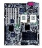
2
1A
1B
3B
3A
2A
2B
DIMM
Sockets
3
IDE
Connector
SCSI A
SCSI B
7
Processor
Socket 1
A
2
COM2
Connector
8
Information in this document is provided in connection with Intel products. No license, express or implied, by estoppel or otherwise, to any intellectual property rights is granted by this document. Except as provided in Intel's Terms and Conditions of Sale for such products, Intel assumes no liability whatsoever, and Intel disclaims any express or implied warranty, relating to sale and/or use of
Intel products including liability or warranties relating to fitness for a particular purpose, merchantability, or infringement of any patent, copyright or other intellectual property right. Intel products are not intended for use in medical, life saving, or life sustaining applications. Intel may make changes to specifications and product descriptions at any time, without notice.
®
Server Products, Programs and Support
Product information including product
briefs and technical product specifications
Sales tools such as videos and
presentations
Configurator Tools to help you build
complete solutions
Training information such as the Intel
Online Learning Center
Support Information and much more
Intel ServerBuilder is your one-stop shop for
information about all of Intel's Server Building
Blocks such as:
Additional resources and support for your server
board, including specifications and software updates, can
be found at:
For a list of qualified memory and chassis components, see:
3. Do not mix processors of different types or
frequencies.
Attaching the Label to the I/O Shield
B
1. Remove the backing from the label included with
your server board.
2. Press the label onto the outside face of the I/O shield.
Outside face
of I/O shield
PARALLEL
KYBD
MOUSE
10/100 MB
NET
1
2
3
USB
®
®
®
®
®
®
®
®
Translations of the
Intel Server Board Product Guide
are available at:
La traducción de la Guía del Producto Intel Server Board
se encuentra disponible en:
•
•
•
•
•
•
•
•
•
•
•