Intel SE7210TP1 User Guide
Intel SE7210TP1 Manual
 |
View all Intel SE7210TP1 manuals
Add to My Manuals
Save this manual to your list of manuals |
Intel SE7210TP1 manual content summary:
- Intel SE7210TP1 | User Guide - Page 1
Intel® Server Board SE7320SP2 / SE7525GP2 User Guide A Guide for Technically Qualified Assemblers of Intel® Identified Subassemblies/Products Order Number: C62033-002 - Intel SE7210TP1 | User Guide - Page 2
for their specific application and environmental conditions. Intel Corporation can not be held responsible if components fail or the server board does not operate correctly when used outside any of their published operating or nonoperating limits. Intel, Intel Pentium, and Intel Xeon are trademarks - Intel SE7210TP1 | User Guide - Page 3
information about which accessories, memory, processors, and third-party hardware have been tested and can be used with your board, and for ordering information for Intel products, see http://www.support.intel.com/support/motherboards/server. Intel Server Board SE7320SP2 / SE7525GP2 User Guide iii - Intel SE7210TP1 | User Guide - Page 4
Supported Memory Power Budget Intel Server Management Driver (for an extensive list of drivers available) Operating System Driver (for operating system drivers) For firmware and BIOS updates Firmware Update For diagnostics test software Diagnostics Intel Server Board SE7320SP2 / SE7525GP2 User - Intel SE7210TP1 | User Guide - Page 5
power, telephone, and communication cables. Turn off the server and disconnect the power cord, telecommunications systems, networks, and modems attached to the server before opening it. Otherwise, personal injury or equipment damage can result. Intel Server Board SE7320SP2 / SE7525GP2 User Guide v - Intel SE7210TP1 | User Guide - Page 6
covers removed. A microprocessor and heat sink may be hot if the system has been running. Also, there may be sharp pins and edges on some board and chassis parts. Contact should be made with care. Consider wearing protective gloves. Intel Server Board SE7320SP2 / SE7525GP2 User Guide vi - Intel SE7210TP1 | User Guide - Page 7
und Gehäuse sollten vorsichtig ausgeführt werden. Sie sollten Schutzhandschuhe tragen. Resource CD http://support.intel.com/support/motherboards/server/safecert.htm 上的 Intel Server Boards and Server Chassis Safety Information(《Intel Intel Server Board SE7320SP2 / SE7525GP2 User Guide vii - Intel SE7210TP1 | User Guide - Page 8
instruction. Consultez Intel Server Boards and Server Chassis Safety Information sur le CD Resource CD ou bien rendez-vous sur le site http://support.intel.com/support/motherboards/server recomienda precaución y el uso de guantes protectores. Intel Server Board SE7320SP2 / SE7525GP2 User Guide viii - Intel SE7210TP1 | User Guide - Page 9
dissipatore di calore potrebbero essere surriscaldati. Fare attenzione alla presenza di piedini appuntiti e parti taglienti sulle schede e sul telaio. È consigliabile l'uso di guanti di protezione. Intel Server Board SE7320SP2 / SE7525GP2 User Guide ix - Intel SE7210TP1 | User Guide - Page 10
Intel Server Board SE7320SP2 / SE7525GP2 User Guide x - Intel SE7210TP1 | User Guide - Page 11
41 Diskette Drive Activity Light Does Not Light 42 CD-ROM Drive or DVD-ROM Drive Activity Light Does Not Light 42 Cannot Connect to a Server 42 Intel Server Board SE7320SP2 / SE7525GP2 User Guide 11 - Intel SE7210TP1 | User Guide - Page 12
Windows* Operating System).. 45 Hard Drive(s) are not Recognized 45 Bootable CD-ROM Is Not Detected 45 LED Information ...46 BIOS Error Messages ...47 BIOS POST Beep Codes 48 BIOS Recovery Beep Codes ...55 Intel® Server Issue Report Form 57 Intel Server Board SE7320SP2 / SE7525GP2 User Guide 12 - Intel SE7210TP1 | User Guide - Page 13
16 Server Board SE7525GP2 Features 17 Configuration Jumper [J17 19 BIOS Select Jumper [J29 19 NIC LEDs...20 Keyboard Commands 31 BIOS Error Messages 47 Beep Codes 48 BIOS Recovery Beep Codes 49 Product Certification Markings 52 Intel Server Board SE7320SP2 / SE7525GP2 User Guide 13 - Intel SE7210TP1 | User Guide - Page 14
Intel Server Board SE7320SP2 / SE7525GP2 User Guide 14 - Intel SE7210TP1 | User Guide - Page 15
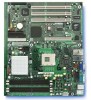
SE7320SP2 provides an additional PCI-Express device for 10/100/1000 Mbits/sec Ethernet LAN connectivity and a 4-port Silicon Image* Serial ATA controller: SI3124. The Server Board SE7320SP2 is shown below. Figure 1. Intel® Server Board SE7320SP2 Intel Server Board SE7320SP2 / SE7525GP2 User Guide - Intel SE7210TP1 | User Guide - Page 16
support via the National* Semiconductor PC87431M integrated management controller providing onboard platform instrumentation. ƒ Intel® Light-Guided Diagnostics on some FRU devices (processors, power) ƒ Port-80 Diagnostic LEDs displaying POST Codes Intel Server Board SE7320SP2 / SE7525GP2 User Guide - Intel SE7210TP1 | User Guide - Page 17
8.0 support via the National* Semiconductor PC87431M integrated management controller providing onboard platform instrumentation. ƒ Light Guided Diagnostics on some FRU devices (Processors, Power) ƒ Port-80 Diagnostic LEDs displaying POST Codes Intel Server Board SE7320SP2 / SE7525GP2 User Guide - Intel SE7210TP1 | User Guide - Page 18
Block Q: System Fan Header 6 KK: Chassis Intrusion Header R: System Fan Header 5 LL: Serial B Header S: Processor 2 Fan Header MM: SCSI LED Connector T: ATA Power Connector Figure 2. Intel Server Board SE7320SP2 / SE7525GP2 Layout Intel Server Board SE7320SP2 / SE7525GP2 User Guide 18 - Intel SE7210TP1 | User Guide - Page 19
reset... Normal Boot 1-2 If these pins are jumpered, the board will boot off of either BIOS (bank.0 or bank 1) depending on which is available first. Force Boot 2-3 If these pins are jumpered, the board will boot off of bank 0 BIOS. Intel Server Board SE7320SP2 / SE7525GP2 User Guide 19 - Intel SE7210TP1 | User Guide - Page 20
Solid Amber Blinking Amber Off Solid Amber Solid Green Description No network connection Network connection in place Transmit/receive activity 10 Mbps connection (if left LED is on or blinking) 100 Mbps connection 1000 Mbps connection Intel Server Board SE7320SP2 / SE7525GP2 User Guide 20 - Intel SE7210TP1 | User Guide - Page 21
1 Fan Header Q. OEM RMC Connector H. System Fan Headers 5 & 6 R. SATA Connectors I. Hot Swap Backplane Header S. Chassis Intrusion Connector J. Processor 21 Fan Header T. Serial B Header Figure 5. Making Connections to the Server Board Intel Server Board SE7320SP2 / SE7525GP2 User Guide 21 - Intel SE7210TP1 | User Guide - Page 22
SE7320SP2 and SE7525GP2 server boards are designed to support one or two Intel® Xeon™ processors utilizing an 800 MHz front side bus with frequencies starting at 2.8 GHz. Previous generations of the Xeon processor are not supported for use on server boards SE7320SP2 and SE7525GP2. Both server boards - Intel SE7210TP1 | User Guide - Page 23
." 2. Turn off all peripheral devices connected to the server. Turn off the server. 3. Disconnect the AC power cord. 4. Remove the server's cover. See your chassis documentation for instructions. 5. Locate the DIMM sockets. See Figure 6. Intel Server Board SE7320SP2 / SE7525GP2 User Guide 23 - Intel SE7210TP1 | User Guide - Page 24
1B DIMM 1A DIMM 2B DIMM 2A Figure 6. Installing Memory TP00684 6. Make sure the clips at either end of or remove. 12. Replace the server's cover. Reconnect any external components you needed to disconnect. 13. Attach the AC power cord. Intel Server Board SE7320SP2 / SE7525GP2 User Guide 24 - Intel SE7210TP1 | User Guide - Page 25
following: (1) Touch the metal chassis before touching the processor or server board. Keep part of your body in contact with the metal chassis to dissipate the static charge while handling the processor. (2) Avoid moving around unnecessarily. Intel Server Board SE7320SP2 / SE7525GP2 User Guide 25 - Intel SE7210TP1 | User Guide - Page 26
the processor into the socket. Lower the socket lever completely. ✏ NOTE Make sure the alignment triangle mark and the alignment triangle cutout align correctly. See Figure 7. A B OM15042 Figure 7. Opening Socket Lever and Attaching Processor Intel Server Board SE7320SP2 / SE7525GP2 User Guide - Intel SE7210TP1 | User Guide - Page 27
Installing Heat Sink over Processor 11. Reconnect or replace any internal components you needed to disconnect or remove. 12. Replace the server's cover. Reconnect any external components you needed to disconnect. 13. Attach the AC power cord. Intel Server Board SE7320SP2 / SE7525GP2 User Guide 27 - Intel SE7210TP1 | User Guide - Page 28
cover. See your chassis documentation for instructions. 5. Server Chassis SC5275-E only: Disconnect the processor fan cable. 6. Fully loosen server's cover. Reconnect any external components you needed to disconnect. 10. Attach the AC power cord. Intel Server Board SE7320SP2 / SE7525GP2 User Guide - Intel SE7210TP1 | User Guide - Page 29
batteri enligt fabrikantens instruktion. VAROITUS Paristo voi räjähtää, jos se on virheellisesti asennettu. Vaihda paristo ainoastaan laitevalmistajan suosittelemaan tyyppiin. Hävitä käytetty paristo valmistajan ohjeiden mukaisesti. Intel Server Board SE7320SP2 / SE7525GP2 User Guide 29 - Intel SE7210TP1 | User Guide - Page 30
internal components you needed to disconnect or remove. 11. Replace the server's cover. Reconnect any external components you needed to disconnect. 12. Attach the AC power cord. 13. Run Setup to restore the configuration settings to the RTC. Intel Server Board SE7320SP2 / SE7525GP2 User Guide 30 - Intel SE7210TP1 | User Guide - Page 31
the plus key has a different scan code than the plus key on the other the exit confirmation window is displayed and the user is asked whether user is returned to where they were before F10 was pressed without affecting any existing values. Intel Server Board SE7320SP2 / SE7525GP2 User Guide 31 - Intel SE7210TP1 | User Guide - Page 32
. Review also any release notes in the release notes file that accompanies the new version of the BIOS. The release notes may contain critical information regarding jumper settings, specific fixes, or other information to complete the upgrade. Intel Server Board SE7320SP2 / SE7525GP2 User Guide 32 - Intel SE7210TP1 | User Guide - Page 33
. 6. Check to make sure the BIOS version displayed during POST is the new version as the system reboots. 7. Enter Setup by pressing the F2 key during boot. 8. In Setup, press the F9 and to set the parameters back to default values. Intel Server Board SE7320SP2 / SE7525GP2 User Guide 33 - Intel SE7210TP1 | User Guide - Page 34
the new language into memory, select Continue with Programming. Press . 6. When the utility displays the message upgrade is complete, remove the diskette. Press . 7. The computer will reboot and the changes will take effect. Intel Server Board SE7320SP2 / SE7525GP2 User Guide 34 - Intel SE7210TP1 | User Guide - Page 35
system. 5. When the system begins beeping, power it down and disconnect the AC power. 6. Return the CMOS Clear jumper to the original location, covering pins 1 and 2. 7. Close the server chassis, reconnect the AC power and power up the system. Intel Server Board SE7320SP2 / SE7525GP2 User Guide 35 - Intel SE7210TP1 | User Guide - Page 36
on jumper block J17. 1. Power down the system and disconnect the AC power. 2. Open the server chassis. 3. Move the jumper from pins 5 and 6 to the Clear Password position, covering pins , covering pins 5 and 6. 7. Close the server chassis. Intel Server Board SE7320SP2 / SE7525GP2 User Guide 36 - Intel SE7210TP1 | User Guide - Page 37
add-in boards and peripheral devices correct? To check these settings, refer to the manufacturer's documentation that comes with them. If applicable, ensure that there are no conflicts-for example, two add-in boards sharing the same interrupt. Intel Server Board SE7320SP2 / SE7525GP2 User Guide 37 - Intel SE7210TP1 | User Guide - Page 38
device drivers properly memory, and chassis lists, as well as the supported LED does light, attempt to boot from a floppy diskette or from a CD-ROM disk. 6. Turn on the system. If the power LED does not light, see "Power Light Does Not Light." Intel Server Board SE7320SP2 / SE7525GP2 User Guide - Intel SE7210TP1 | User Guide - Page 39
loose. ‰ Have you securely plugged the server AC power cord into the power supply? ‰ Is the power supply correctly set to 110V or 235V, depending on your power output? ‰ Will other items plugged into the same power outlet function correctly? Intel Server Board SE7320SP2 / SE7525GP2 User Guide 39 - Intel SE7210TP1 | User Guide - Page 40
in the BIOS? ‰ memory DIMMs and re-seat them. ‰ Make sure the processor(s) comply with the system requirements. ‰ Make sure the processor(s) have been populated according to the system requirements. ‰ Remove the processor(s) and re-seat them. Intel Server Board SE7320SP2 / SE7525GP2 User Guide - Intel SE7210TP1 | User Guide - Page 41
panel board and to the server board? ‰ Are the power supply cables properly connected to the server board? ‰ Are there any shorted wires caused by pinched-cables or have power connector plugs been forced into power connector sockets the wrong way? Intel Server Board SE7320SP2 / SE7525GP2 User Guide - Intel SE7210TP1 | User Guide - Page 42
as the network controller. ‰ Make sure the correct networking software is installed. ‰ If you are directly connecting two servers (without a hub), you will need a crossover cable. ‰ Check the network controller LEDs next to the NIC connectors. Intel Server Board SE7320SP2 / SE7525GP2 User Guide 42 - Intel SE7210TP1 | User Guide - Page 43
in, a signal may be sent to the command the system to boot. Before installing a PCI card, you should always: ‰ Turn off the server power by using the power button on the front of the system. ‰ Unplug the AC power cord(s) from the server. Intel Server Board SE7320SP2 / SE7525GP2 User Guide 43 - Intel SE7210TP1 | User Guide - Page 44
correct device drivers installed. If the problems persist, contact the software vendor's customer service representative. Problems with Application Software that Ran Correctly Earlier Problems that the power outlet and the system power cord. Intel Server Board SE7320SP2 / SE7525GP2 User Guide 44 - Intel SE7210TP1 | User Guide - Page 45
using a RAID configuration with SCSI or SATA drives, make sure the RAID card is installed correctly. Bootable CD-ROM Is Not Detected Check the following: ‰ Make sure the BIOS is configured to allow the CD-ROM to be the first bootable device. Intel Server Board SE7320SP2 / SE7525GP2 User Guide 45 - Intel SE7210TP1 | User Guide - Page 46
CPU 1 & 2 Fault 5v Standby Power LED Identify failing memory module Display boot 80 POST code Warn on fan failure Identify fan failure Identify processor failure Identify 5v standby power on state Identify the power state of the system Control panel and board left side DIMM end front of board - Intel SE7210TP1 | User Guide - Page 47
and has been updated. Updated Failed NVRAM was invalid but was unable to be updated. Keyboard Error Error in the keyboard connection. Make sure keyboard is connected properly. KB/Interface Error Keyboard interface test failed. continued Intel Server Board SE7320SP2 / SE7525GP2 User Guide 47 - Intel SE7210TP1 | User Guide - Page 48
) 6 8042 GateA20 cannot be toggled (memory failure or not present) 7 Exception interrupt error 8 Display memory R/W error 9 (Reserved; not used) 10 CMOS Shutdown register test error 11 Invalid BIOS (such as, POST module not found) Intel Server Board SE7320SP2 / SE7525GP2 User Guide 48 - Intel SE7210TP1 | User Guide - Page 49
known as "beep codes. These beeps have a code that identifies system or PCI card events. For example, some Intel® RAID cards have beep codes. Before checking for a system beep code error make sure the PCI card is not causing the beeping. Intel Server Board SE7320SP2 / SE7525GP2 User Guide 49 - Intel SE7210TP1 | User Guide - Page 50
Intel Server Board SE7320SP2 / SE7525GP2 User Guide 50 - Intel SE7210TP1 | User Guide - Page 51
is required to comply with Class A emission requirements as it is intended for a commercial type market place. Intel targets 10db margin to Class A Limits The Server Board SE7320SP2 / SE7525GP2 has been has been tested and verified to comply with the following electromagnetic compatibility (EMC - Intel SE7210TP1 | User Guide - Page 52
Europe FCC Marking (Class A) USA EMC Marking (Class A) Canada BSMI Marking (Class A) Taiwan CANADA ICES-003 CLASS A CANADA NMB-003 CLASSE A RRL MIC Mark Korea Intel Server Board SE7320SP2 / SE7525GP2 User Guide 52 - Intel SE7210TP1 | User Guide - Page 53
radio frequency energy and, if not installed and used in accordance with the instructions, may cause harmful interference to radio communications. However, there is no guarantee grounded may result in interference to radio and TV reception. Intel Server Board SE7320SP2 / SE7525GP2 User Guide 53 - Intel SE7210TP1 | User Guide - Page 54
certificate from local Intel representative 3. Name of Certification Recipient: Intel Corporation 4. Date of Manufacturer: Refer to date code on product 5. Manufacturer/Nation: Intel Corporation/Refer to country of origin marked on product Intel Server Board SE7320SP2 / SE7525GP2 User Guide 54 - Intel SE7210TP1 | User Guide - Page 55
support.intel.com/support/motherboards/server. Telephone All calls are billed US $25.00 per incident, levied in local currency at the applicable credit card exchange rate plus applicable taxes. (Intel Singapore 65 6213-1311 India 0006517 2 68303634 (manual toll-free. From India, you need an IDD - Intel SE7210TP1 | User Guide - Page 56
222 1288. Once connected, dial 800 843 4481 Paraguay 001 916 377 0114 Peru 001 916 377 0114 Uruguay 001 916 377 0114 For an updated support contact list, see http://www.intel.com/support/9089.htm/ Intel Server Board SE7320SP2 / SE7525GP2 User Guide 56 - Intel SE7210TP1 | User Guide - Page 57
is available at http://support.intel.com/support/motherboards/server/ . For the fastest service, please submit your form via the Internet. Date Submitted: Company Name: Contact Name: Email Address: Intel Server Product: Priority (Critical, Hot, High, Low): Brief Problem Description. Provide a brief - Intel SE7210TP1 | User Guide - Page 58
System Version Service Pack Peripheral Information Board NIC1 (1 Gb) ˆ On-Board NIC2 (1 Gb) Driver Revision IRQ # I/O Base Address FW Rev# Hard Drive Information: ˆ ATA # of drives installed: Make/Model/Firmware Revision ˆ SCSI # of drives installed: Make/Model/Firmware Revision ˆ SATA - Intel SE7210TP1 | User Guide - Page 59
Issue Report Form Complete Problem Description In the space below, provide a complete description of the steps used to reproduce the problem or a complete description of where the problem can be found. Please also include any details on troubleshooting already done. 59 - Intel SE7210TP1 | User Guide - Page 60
60
-
 1
1 -
 2
2 -
 3
3 -
 4
4 -
 5
5 -
 6
6 -
 7
7 -
8
-
9
-
10
-
11
-
12
-
13
-
14
-
15
-
16
-
17
-
18
-
19
-
20
-
21
-
22
-
23
-
24
-
25
-
26
-
27
-
28
-
29
-
30
-
31
-
32
-
33
-
34
-
35
-
36
-
37
-
38
-
39
-
40
-
41
-
42
-
43
-
44
-
45
-
46
-
47
-
48
-
49
-
50
-
51
-
52
-
53
-
54
-
55
-
56
-
57
-
58
-
59
-
60
 |
 |

Intel
®
Server Board SE7320SP2 /
SE7525GP2 User Guide
A Guide for Technically Qualified Assemblers of Intel
®
Identified
Subassemblies/Products
Order Number:
C62033-002