Intel SE7520BD2SCSI User Guide
Intel SE7520BD2SCSI - E7520 DP PGA604 MAX-12GB Manual
 |
UPC - 735858167437
View all Intel SE7520BD2SCSI manuals
Add to My Manuals
Save this manual to your list of manuals |
Intel SE7520BD2SCSI manual content summary:
- Intel SE7520BD2SCSI | User Guide - Page 1
Intel® Server Board SE7520BD2 User Guide A Guide for Technically Qualified Assemblers of Intel® Identified Subassemblies/Products Order Number: C51518-007 - Intel SE7520BD2SCSI | User Guide - Page 2
board does not operate correctly when used outside any of their published operating or nonoperating limits. Intel, Intel Pentium, and Intel Xeon are trademarks or registered trademarks of Intel Corporation or its subsidiaries in the United States and other countries. * Other names and brands may be - Intel SE7520BD2SCSI | User Guide - Page 3
components you may need, troubleshooting information, and instructions on how to add and replace components on the Intel® Server Board SE7520BD2. For the latest version of this manual, refer to http://support.intel.com/support/motherboards/server/SE7520BD2/. Manual Organization Chapter 1 provides - Intel SE7520BD2SCSI | User Guide - Page 4
with this product Chassis that have been tested with this product Obtain this document / software Intel® Server Board SE7520BD2 Technical Product Specification Intel® Server Board SE7520BD2 Quick Start User's Guide located in the product box or to obtain a newer version, use this link: Quick Start - Intel SE7520BD2SCSI | User Guide - Page 5
and drivers Supported Processor List Tested Memory List Power Budget Tool Intel® Server Management Software Download Finder To obtain the documents or software mentioned in the above table and for the latest product technical information, please go to: http://support.intel.com/support/motherboards - Intel SE7520BD2SCSI | User Guide - Page 6
sides can damage the contacts inside the jumper, causing intermittent problems with the function controlled by that jumper. Take care to grip instructions. See also Intel Server Boards and Server Chassis Safety Information on the Deployment CD and/or at http://support.intel.com/support/motherboards - Intel SE7520BD2SCSI | User Guide - Page 7
garde indiquées dans ce document avant de suivre toute instruction. Consultez Intel Server Boards and Server Chassis Safety Information sur le CD Resource CD ou bien rendez-vous sur le site http://support.intel.com/support/motherboards/server/sb/CS-010770.htm Instrucciones de seguridad importantes - Intel SE7520BD2SCSI | User Guide - Page 8
Preface viii - Intel SE7520BD2SCSI | User Guide - Page 9
the System ...46 Problems following Initial System Installation 46 First Steps Checklist...46 Hardware Diagnostic Testing 47 Confirming Loading of the Operating System 48 Specific Problems and Corrective Actions 48 Power Light Does Not Light 48 Intel® Server Board SE7520BD2 User Guide ix - Intel SE7520BD2SCSI | User Guide - Page 10
Connect to a Server 51 Problems with Network 51 System Boots when Installing PCI Card 52 Problems with Newly Installed Application Software 52 Problems with Application Software that Ran Conformity (BSMI 59 Korean Compliance (RRL 59 Getting Help ...60 Intel® Server Issue Report Form 62 x - Intel SE7520BD2SCSI | User Guide - Page 11
Memory...29 Figure 7. Opening Socket Lever 31 Figure 8. Inserting Processor...31 Figure 9. Closing Socket Lever 32 Figure 10. Installing Configuration Jumpers 22 Table 4. NIC LEDs ...23 Table 5. Intel® Server Chassis Supported for each Server Board SE7520BD2 Product Code.. 24 Table 6. Keyboard - Intel SE7520BD2SCSI | User Guide - Page 12
Contents xii - Intel SE7520BD2SCSI | User Guide - Page 13
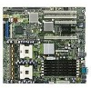
, a list of the server board features, and diagrams showing the location of important components and connections on the server board. Figure 1. Intel® Server Board SE7520BD2 Six product codes for the Server Board SE7520BD2 are available. The following table provides an overview of the differences - Intel SE7520BD2SCSI | User Guide - Page 14
PCI Express x4 One PCI-X* 133MHz Two PCI-X 100MHz One PCI 32-bit / 33MHz 5V SATA USB Connections Dual serial ATA channels with support for RAID 0 and 1. One IDE connector supporting two ATA/100 IDE channels. Five: - Three at rear of board - Two at front of board Dual serial ATA channels with - Intel SE7520BD2SCSI | User Guide - Page 15
-X 100MHz One PCI 32-bit / 33MHz 5V Two Ultra320/LVD channels via the LSI* 53C1030 SCSI controller Dual serial ATA channels with support for RAID 0 and 1. One IDE connector supporting two ATA/100 IDE channels. Five: - Three at rear of board - Two at front of board One PCI Express* x8 One PCI - Intel SE7520BD2SCSI | User Guide - Page 16
-bit / 33MHz 5V One Ultra320/LVD channel via either the LSI* 53C1020 or LSI* 53C1020A SCSI controller Dual serial ATA channels with support for RAID 0 and 1. One IDE connector supporting two ATA/100 IDE channels. Four: - Two at rear of board - Two at front of board One PCI Express x4 One PCI - Intel SE7520BD2SCSI | User Guide - Page 17
to provide a second, optional serial port (Serial B) ƒ One IDE connector supporting up to two ATA-100 compatible devices ƒ One standard floppy drive interface ƒ Integrated critical sensor information. ƒ Intel® Light-Guided Diagnostics on critical FRU devices, such as processors, memory, and power - Intel SE7520BD2SCSI | User Guide - Page 18
Server Board Features Connector and Header Locations Product Codes SE7520BD2, SE7520BD2SCSI, SE7520BD2V G A BCDE F H I L J KM TT SS RR QQ PP NN OO MM LL KK JJ II HH GG FF CPU 2 DD BB Z X W EE AA VU T CC Y N O P Q R CPU 1 S TP00718 18 - Intel SE7520BD2SCSI | User Guide - Page 19
Left x8 (x4speed) PCI-Express* Slot F, Right x8 PCI-Express Slot G Intel® 82541P1 (10/100/1000) H PCI-X 133 Slot I Battery P CPU Power Connector Q DIMM Sockets R CPU 1 Fan Header S CPU 1 T CPU 2 U Intel® Management Module Connector V IDE Connector W Floppy Connector X System Fan 2 (3-pin) Y - Intel SE7520BD2SCSI | User Guide - Page 20
Server Board Features Product Codes SE7520BD2SCSID2, SE7520BD2VD2, SE7520BD2SATAD2 G A BCDE F H I L J KM TT SS RR QQ PP NN OO MM LL KK JJ II HH GG FF CPU 2 DD BB Z X W EE AA VU T CC Y CPU 1 N O P O Q R S TP01688 20 - Intel SE7520BD2SCSI | User Guide - Page 21
Super I/O D PCI Slot 32/33 E ATI* Rage XL Graphics Controller F, Left x8 (x4speed) PCI-Express* Slot F, Right x8 PCI-Express Slot G Intel® 82541P1 (10/100/1000) H PCI-X 133 Slot I Battery J ICMB Connector K System Fan 5 L System Fan 6 M System I/O Connectors N Auxiliary Power Connector O Main Power - Intel SE7520BD2SCSI | User Guide - Page 22
J4H2 PASSWORD CLEAR TP00723 Figure 4. Configuration Jumper Location Table 3. Configuration Jumpers Jumper Name Pins What happens at system reset... CMOS Clear 1-2 BMC Control: These pins should be jumpered for normal operation. (J2H1) 2-3 Force Erase: If these pins are jumpered, the CMOS - Intel SE7520BD2SCSI | User Guide - Page 23
and SE7520BD2SCSI Figure 5. Back Panel Connectors The NIC LEDs at the right and left of the NICs provide the following information. See the Intel® Server Board SE7520BD2 Technical Product Specification for POST code errors. Table 4. NIC LEDs LED LED State Off Left LED Solid Green Blinking - Intel SE7520BD2SCSI | User Guide - Page 24
both must be of identical revision, core voltage, cache size, and bus/core speed. When a single processor is installed, it must be in the socket labeled CPU1. For a link to the complete list of supported processors, see: http://support.intel.com/support/motherboards/server/se7520bd2/sb/CS-013540.htm - Intel SE7520BD2SCSI | User Guide - Page 25
Server Board Features Memory For a list of supported memory DIMMs, see: http://support.intel.com/support/motherboards/server/se7520bd2/sb/CS-013543.htm. Product Codes SE7520BD2, SE7520BD2SCSI, and SE7520BD2V Product codes SE7520BD2, SE7520BD2SCSI, and SE7520BD2V include three banks of DIMMs across - Intel SE7520BD2SCSI | User Guide - Page 26
1B, DIMM 2A, DIMM 2B, DIMM 3A, and DIMM 3B have been populated. Memory Mirroring and Memory On-line Sparing The Intel® E7520 chipset includes hardware that supports memory mirroring and memory on-line sparing. Both memory mirroring and memory on-line sparing provide a way to prevent data loss in - Intel SE7520BD2SCSI | User Guide - Page 27
memory on-line sparing is used, the spare DIMMs must be equal to or larger than the largest in-service DIMM in that channel. For additional information, see the Intel® Server Board SE7520BD2 Technical Product Specification. Power Supply The minimum power supply required depends on the server chassis - Intel SE7520BD2SCSI | User Guide - Page 28
close attention to the "Safety Information" at the beginning of this manual. ✏ NOTES Most diagrams in this manual show product code SE7520BD2. Where necessary to complete a procedure, differences a link to the list of tested DIMMs for this server board. Intel® Server Board SE7520BD2 User Guide 28 - Intel SE7520BD2SCSI | User Guide - Page 29
the server. 4. Remove the chassis cover. See your chassis documentation for instructions. 5. Locate the DIMM sockets. See Figure 6. ✏ NOTES The product code SE7520BD2. If you are using a Server Board SE7520BD2 that supports DDR2 memory DIMMs, your server board will have eight DIMM sockets instead - Intel SE7520BD2SCSI | User Guide - Page 30
may damage the server board if you install a processor that is inappropriate for your server. See Supported Processor List for compatible processor(s). ESD and handling processors: Reduce the risk of electrostatic discharge (ESD) damage to the processor by doing the following: (1) Touch the metal - Intel SE7520BD2SCSI | User Guide - Page 31
Hardware Installations and Upgrades Installing the Processor To install a processor, follow these instructions: 1. Observe the safety and ESD precautions at the beginning of this book. 2. Turn off all peripheral devices connected to the server. Turn off the server. 3. - Intel SE7520BD2SCSI | User Guide - Page 32
not fully tighten one screw before tightening another. 4. Gradually and equally tighten each captive screw until all screws are tight. ✏ NOTE Boxed processor thermal solutions differ depending on the chassis. See the boxed processor documentation for specifc instructions for the thermal solution. 32 - Intel SE7520BD2SCSI | User Guide - Page 33
Hardware Installations and Upgrades Note: Heat sink styles may differ. Server Board Cutaway Heat Sink Retainer [CEK Spring] TP00721 Figure 10. Installing the Heat Sink 33 - Intel SE7520BD2SCSI | User Guide - Page 34
cord from the server. 4. Remove the chassis cover. 5. Unplug the processor fan cable from the server board. 6. Loosen the four captive screws Remove the chassis cover. 2. See the chassis Quick Start User's Guide for instructions on removing any chassis cooling ducts prior to installing or removing a - Intel SE7520BD2SCSI | User Guide - Page 35
example, the date and time) may be wrong. Contact your customer service representative or dealer for a list of approved devices. WARNING Danger of manufacturer. Discard used batteries according to manufacturer's instructions. ADVARSEL! Lithiumbatteri - Eksplosionsfare ved fejlagtig håndtering - Intel SE7520BD2SCSI | User Guide - Page 36
Hardware Installations and Upgrades TP00724 Figure 11. Replacing the Backup Battery 7 Dispose of the old battery according to local ordinance. 8 Remove the new lithium battery from its package, and observe the correct polarity. The flat side of the battery that has a "+" on it must face toward the - Intel SE7520BD2SCSI | User Guide - Page 37
If you are not able to access BIOS Setup, you might need to clear the CMOS memory. For instructions on clearing the CMOS, see "Clearing the CMOS". Setup Menus Each BIOS Setup menu page contains a for any reason, the feature's value field is inaccessible. Intel® Server Board SE7520BD2 User Guide 37 - Intel SE7520BD2SCSI | User Guide - Page 38
Server Utilities Table 6 describes the keyboard commands you can use in the BIOS Setup menus. Table 6. Keyboard Commands Press Description Help - Pressing F1 on any menu invokes the general Help window. The left and right arrow keys are used to move between the major menu pages. The keys - Intel SE7520BD2SCSI | User Guide - Page 39
Server Utilities Upgrading the BIOS ✏ NOTE These instructions describe the process of updating the BIOS only. It is recommented that you check the Intel website Download Finder for the System Update Package (SUP). The SUP contains the BIOS, FRU/SDR and HSC firmware all in one easy to install - Intel SE7520BD2SCSI | User Guide - Page 40
the values and exit Setup. 8. In the unlikely event that a BIOS error occurs during the BIOS update process, see "Recovering the BIOS" for instructions on performing a BIOS recovery. Other Bootable Storage Update 1. Copy the afudos.exe, f.bat, fbb.bat, and the .ROM files to a bootable storage such - Intel SE7520BD2SCSI | User Guide - Page 41
a BIOS update. You may encounter a CMOS Checksum error or other problem after reboot. If so, try shutting down the system and restarting. instructions on performing a BIOS recovery. You can obtain the Recovery.zip file which is packaged together with the BIOS Update Package from the Intel Support - Intel SE7520BD2SCSI | User Guide - Page 42
that the BIOS becomes damaged, a recovery process needs to be followed to return the system to service. Two methods are available to recover the BIOS: automatically with the crisis recovery diskette, and manually by moving a jumper on the system board. These methods are described below. ✏ NOTE BIOS - Intel SE7520BD2SCSI | User Guide - Page 43
initiated. This option would be used only when the BIOS is corrupt, but the ROM checksum error does not occur during POST. To manually initiate a BIOS recovery, use the following steps: 1. Power down and uplug the system from the AC power source. 2. Install the recovery jumper at J4H1. See - Intel SE7520BD2SCSI | User Guide - Page 44
Server Utilities Clearing the Password If the user or administrator password(s) is lost or forgotten, install a jumper on jumper block J4H3 to remove both passwords. The Password Clear jumper must be removed before a new password(s) can be set. 1. Power down the system and disconnect the AC power. - Intel SE7520BD2SCSI | User Guide - Page 45
Server Utilities Clearing the CMOS If you are not able to access the BIOS setup screens, the Clear CMOS jumper will need to be used to reset the configuration RAM. The Clear CMOS jumper is located on jumper block J2H1. 1. Power down the system and disconnect the AC power. 2. Open the server. 3. Move - Intel SE7520BD2SCSI | User Guide - Page 46
, such as video drivers, network drivers, and SCSI drivers. Intel provides a package called the "Platform Confidence Test" that may help with your diagnostics. See "Additional Information and Software" for a link to this software. If you are unable to resolve your server problems on your own, see - Intel SE7520BD2SCSI | User Guide - Page 47
Troubleshooting ‰ Are all peripheral devices installed correctly? ‰ If the system has a hard disk drive, is it properly formatted or configured? ‰ Are all device drivers lists, as well as the supported hardware and operating system list. See identifying a hardware problem and locating its source - Intel SE7520BD2SCSI | User Guide - Page 48
Troubleshooting Verifying Proper Operation of Key System Lights As POST is not detected. Try the following solutions in the order given. If you cannot correct the problem, contact your service representative or authorized dealer for help. Power Light Does Not Light Check the following: ‰ Did - Intel SE7520BD2SCSI | User Guide - Page 49
Troubleshooting processor(s) comply with the system requirements. ‰ Make sure the processor(s) have been populated according to the system requirements. ‰ Carefully remove the processor beep code you hear. This information is useful for your service representative. 5. If you do not receive a beep code - Intel SE7520BD2SCSI | User Guide - Page 50
Troubleshooting Characters Are Distorted or Incorrect Check the following: ‰ Are the brightness and contrast controls properly adjusted on the video monitor? See the manufacturer's documentation. ‰ Are - Intel SE7520BD2SCSI | User Guide - Page 51
Troubleshooting Problems with Network The server hangs when the drivers are loaded. ‰ Certain drivers may require interrupts that are not shared with other PCI drivers. For these drivers sure the other adapter supports shared interrupts. Make sure your operating system supports shared interrupts. ‰ - Intel SE7520BD2SCSI | User Guide - Page 52
Troubleshooting System Boots when Installing PCI Card System Server Management features the correct device drivers are installed. If the problems persist, contact the software vendor's customer service representative. Problems with Application Software that Ran Correctly Earlier Problems that occur - Intel SE7520BD2SCSI | User Guide - Page 53
systems do not include all of the drivers for the Intel® chipsets, on-board NICs, and troubleshooting your system. A table of these LEDs with a description of their use can be found in the Intel® Server Board SE7520BD2 Technical Product Specification at: http://support.intel.com/support/motherboards - Intel SE7520BD2SCSI | User Guide - Page 54
Troubleshooting BIOS POST Beep Codes Boot Block Error Beep Codes Table 7. Boot Block Error base memory (first 64KB block) 3 Base memory read / write test error 4 Motherboard timer not operational 5 Processor error 6 8042 Gate A20 test error (cannot switch to protected mode) 7 General - Intel SE7520BD2SCSI | User Guide - Page 55
Table 9. BIOS Beep Codes Number of Troubleshooting Action Beeps 1, 2 or 3 Reseat the memory, or replace with known good modules. 4-7, 9-11 Fatal error indicating a serious problem with the system. Consult your system manufacturer. Before declaring the motherboard beyond all hope, eliminate the - Intel SE7520BD2SCSI | User Guide - Page 56
requirements as it is intended for a commercial type market place. Intel targets 10db margin to Class A Limits The Intel® Server Board SE7520BD2 has been tested and verified to comply (Belarus) ƒ RRL MIC Notice No. 1997-41 (EMC) & 1997-42 (EMI) (Korea) Intel® Server Board SE7520BD2 User Guide 56 - Intel SE7520BD2SCSI | User Guide - Page 57
Regulatory and Compliance Information Certifications/Registrations/Declarations ƒ UL Certification (US/Canada) ƒ CE Declaration of Conformity (CENELEC Europe) ƒ FCC/ICES-003 Class A Attestation (USA/Canada) ƒ C-Tick Declaration of Conformity (Australia) ƒ MED Declaration of Conformity (New Zealand) - Intel SE7520BD2SCSI | User Guide - Page 58
For questions related to the EMC performance of this product, contact: Intel Corporation 5200 N.E. Elam Young Parkway Hillsboro, OR 97124-6497 1-800-628 and, if not installed and used in accordance with the instructions, may cause harmful interference to radio communications. However, there is - Intel SE7520BD2SCSI | User Guide - Page 59
Product 2. Certification No.: On RRL certificate. Obtain certificate from local Intel representative 3. Name of Certification Recipient: Intel Corporation 4. Date of Manufacturer: Refer to date code on product 5. Manufacturer/Nation: Intel Corporation/Refer to country of origin marked on product 59 - Intel SE7520BD2SCSI | User Guide - Page 60
support.intel.com/support/motherboards/server/SE7520BD2 Telephone All calls are billed US $25.00 per incident, levied in local currency at the applicable credit card exchange rate plus applicable taxes. (Intel 65 6213-1311 India 0006517 2 68303634 (manual toll-free. From India, you need an - Intel SE7520BD2SCSI | User Guide - Page 61
1288. Once connected, dial 800 843 4481 Paraguay 001 916 377 0114 Peru 001 916 377 0114 Uruguay 001 916 377 0114 For an updated support contact list, see http://www.intel.com/support/9089.htm/ 61 - Intel SE7520BD2SCSI | User Guide - Page 62
Entry Server Chassis SC5295-E DP ˆ Intel® Entry Server Chassis SC5295-E BRP ˆ Other Reference Chassis (Vendor / Model): Board Accessories Installed ˆ Intel® Management Module, Advanced or Professsional (specify) Indicate the BMC firmware version Intel® Server Board SE7520BD2 User Guide 62 - Intel SE7520BD2SCSI | User Guide - Page 63
Intel® Server Issue Report Form Operating System Information Operating System Version Service Pack / Kernel Version General Information 100/1000 Mb) On-board NIC2 (10/100/1000Mb) Card or Peripheral Description Driver IRQ # Revision I/O Base Address FW Rev# Hard Drive Information: ˆ IDE - Intel SE7520BD2SCSI | User Guide - Page 64
Intel® Server Issue Report Form Complete Issue Description In the space below, provide a complete description of the steps used to reproduce the issue or a complete description of where the problem can be found. Please also include any details on troubleshooting already done. 64
-
 1
1 -
 2
2 -
 3
3 -
 4
4 -
 5
5 -
 6
6 -
 7
7 -
8
-
9
-
10
-
11
-
12
-
13
-
14
-
15
-
16
-
17
-
18
-
19
-
20
-
21
-
22
-
23
-
24
-
25
-
26
-
27
-
28
-
29
-
30
-
31
-
32
-
33
-
34
-
35
-
36
-
37
-
38
-
39
-
40
-
41
-
42
-
43
-
44
-
45
-
46
-
47
-
48
-
49
-
50
-
51
-
52
-
53
-
54
-
55
-
56
-
57
-
58
-
59
-
60
-
61
-
62
-
63
-
64
 |
 |

Intel® Server Board SE7520BD2
User Guide
A Guide for Technically Qualified Assemblers of Intel
®
Identified
Subassemblies/Products
Order Number:
C51518-00
7