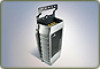
Intermec IV7 IV7 Vehicle-Mount Reader Instructions (for standard mounting plat
Intermec IV7 Manual
 |
View all Intermec IV7 manuals
Add to My Manuals
Save this manual to your list of manuals |
Intermec IV7 manual content summary:
- Intermec IV7 | IV7 Vehicle-Mount Reader Instructions (for standard mounting plat - Page 1
IV7 Vehicle-Mount Reader Instructions - Intermec IV7 | IV7 Vehicle-Mount Reader Instructions (for standard mounting plat - Page 2
98203 U.S.A. www.intermec.com The information contained herein is provided solely for the purpose of allowing customers to operate and service Intermec-manufactured equipment and ; 6,784,789; 6,816,063. There may be other U.S. and foreign patents pending. ii IV7 Vehicle-Mount Reader Instructions - Intermec IV7 | IV7 Vehicle-Mount Reader Instructions (for standard mounting plat - Page 3
the IV7 Firmware 11 Upgrading With SmartSystems Foundation 11 Upgrading With Windows XP 12 Sending Commands to the IV7 13 Understanding the GPIO Interfaces 13 Port Pin Assignments 14 Where to Go for More Information 15 Specifications 16 Notification 16 IV7 Vehicle-Mount Reader Instructions - Intermec IV7 | IV7 Vehicle-Mount Reader Instructions (for standard mounting plat - Page 4
iv IV7 Vehicle-Mount Reader Instructions - Intermec IV7 | IV7 Vehicle-Mount Reader Instructions (for standard mounting plat - Page 5
template, and these instructions. IV7 Vehicle-Mount Reader Out of Box Contents To install the IV7, you also need these items (purchased separately): • IV7 DC Power Cable Kit (P/N 203-713-002 with right-angle connector, or 203-713-003 with straight connector) • Appropriate RFID antennas and cables - Intermec IV7 | IV7 Vehicle-Mount Reader Instructions (for standard mounting plat - Page 6
Power Port, and Data Port Locations Antenna port (4 places) IV7 Antenna Port Locations Note: The IV7 ships with terminators installed on antenna ports 2, 3, and 4. Do not remove the terminator from any port unless you are installing an antenna on that port. 6 IV7 Vehicle-Mount Reader Instructions - Intermec IV7 | IV7 Vehicle-Mount Reader Instructions (for standard mounting plat - Page 7
your installation. The template is included in the IV7 documentation packet. Antenna cable tie-wrap slots (5 places) Mounting hole for M5 (1/4-in O.D.) hardware (4 places) Mounting hole for M8 (3/8-in O.D.) hardware (2 places) IV7 Mounting Hole Locations IV7 Vehicle-Mount Reader Instructions 7 - Intermec IV7 | IV7 Vehicle-Mount Reader Instructions (for standard mounting plat - Page 8
a firewall or other sheet metal. Note: Most vehicle manufacturers offer pulley kits for installation of wiring with risers. Intermec recommends using these manufacturerspecific kits with any installation of the IV7 on a forklift load back rest assembly. 8 IV7 Vehicle-Mount Reader Instructions - Intermec IV7 | IV7 Vehicle-Mount Reader Instructions (for standard mounting plat - Page 9
, connect the serial cable to COM1 or COM2. RFID antenna (up to 4) Power port To 6-60 VDC To PC serial port and GPIO devices Data port 8 Connect the power cable to the power port on the IV7. The power indicator turns green. The IV7 is now ready to use. IV7 Vehicle-Mount Reader Instructions 9 - Intermec IV7 | IV7 Vehicle-Mount Reader Instructions (for standard mounting plat - Page 10
tap RFID > Reader > Reader 1. The Reader 1 module appears. 3 Select the Enable Reader check box. 4 Tap File > Save Settings. 5 Tap View > Refresh. The Enable Reader check box should be selected and the Connected check box should be selected and grayed out. 10 IV7 Vehicle-Mount Reader Instructions - Intermec IV7 | IV7 Vehicle-Mount Reader Instructions (for standard mounting plat - Page 11
. To download IV7 firmware 1 Go to www.intermec.com and choose Support > Downloads. 2 In the Product Category list, choose RFID. 3 In the Product Family list, choose Vehicle Mount Readers. 4 In the Product list, choose IV7 Vehicle Mount and click Submit. The IV7 Vehicle Mount Downloads page appears - Intermec IV7 | IV7 Vehicle-Mount Reader Instructions (for standard mounting plat - Page 12
upgrade files as described in "Upgrading the IV7 Firmware" on page 11. 2 Double-click the installer package (XP_x86_IV7_yy.yy.exe, where yy.yy is the firmware version). The opening screen appears. Follow the steps in the wizard to upgrade the IV7 firmware. 12 IV7 Vehicle-Mount Reader Instructions - Intermec IV7 | IV7 Vehicle-Mount Reader Instructions (for standard mounting plat - Page 13
can then trigger IV7 operations. All GPIO interfaces should be restricted to a maximum operating input voltage of +5 VDC. To use higher input voltages, you need to use an external voltage conditioning network, such as resistor dividers or active regulators. IV7 Vehicle-Mount Reader Instructions 13 - Intermec IV7 | IV7 Vehicle-Mount Reader Instructions (for standard mounting plat - Page 14
the interfaces are not protected from continuous over voltage or over current conditions. The IV7 will be damaged if a low impedance source greater than +6.5 VDC is connected Assignments 3 1 4 6 8 10 13 15 2 5 7 9 12 14 16 17 19 11 IV7 Data Port 18 20 14 IV7 Vehicle-Mount Reader Instructions - Intermec IV7 | IV7 Vehicle-Mount Reader Instructions (for standard mounting plat - Page 15
GP Output 2 20 GP Output 3 1 2 3 IV7 Power Port Power Port Pin Assignments Pin Description 1 -VDC 2 +VDC 3 Ground Where to Go for More Information Visit the Intermec web site at www.intermec.com to download PDF versions of our current manuals. IV7 Vehicle-Mount Reader Instructions 15 - Intermec IV7 | IV7 Vehicle-Mount Reader Instructions (for standard mounting plat - Page 16
RFID radio model designation IM5; Certification number 003AFA080976. Worldwide Headquarters 6001 36th Avenue West Everett, Washington 98203 U.S.A. tel 425.348.2600 fax 425.355.9551 www.intermec.com © 2010 Intermec Technologies Corporation. All rights reserved. IV7 Vehicle-Mount Reader Instructions
-
 1
1 -
 2
2 -
 3
3 -
 4
4 -
 5
5 -
 6
6 -
 7
7 -
8
-
9
-
10
-
11
-
12
-
13
-
14
-
15
-
16
 |
 |

IV
7
Vehicle-Mount Reader
Instructions