Intermec IV7 Intermec RFID System Manual
Intermec IV7 Manual
 |
View all Intermec IV7 manuals
Add to My Manuals
Save this manual to your list of manuals |
Intermec IV7 manual content summary:
- Intermec IV7 | Intermec RFID System Manual - Page 1
System Manual Intermec RFID - Intermec IV7 | Intermec RFID System Manual - Page 2
to operate and service Intermec-manufactured equipment and is not to be released, reproduced, or used for any other purpose without written permission of Intermec. Information and specifications intention of infringement. There are U.S. and foreign patents pending. ii Intermec RFID System Manual - Intermec IV7 | Intermec RFID System Manual - Page 3
Services and Support vii Warranty Information vii Web Support vii Telephone Support viii Who Should Read This Manual viii Related Documents ix 1 Learning About RFID Systems 1 What is an RFID System 2 About RFID for Controlling RFID System Performance 19 Intermec RFID System Manual iii - Intermec IV7 | Intermec RFID System Manual - Page 4
Noise and Interference 36 Sources That Produce Electrical Noise in the RF Field 36 Other Sources of Electrical Noise 36 Solving Electrical Noise and Interference Problems 36 How to Choose the Right Reader 37 Application Type 37 Frequencies and Bandwidth 38 iv Intermec RFID System Manual - Intermec IV7 | Intermec RFID System Manual - Page 5
Formulas 55 Relationship Between Field Strength and Power Density 55 Converting Field Strength to Decibels (dB 56 Converting Power Density to Decibels (dB 56 How Readers Decode the Radio Signal 57 I Index 59 Intermec RFID System Manual v - Intermec IV7 | Intermec RFID System Manual - Page 6
Contents vi Intermec RFID System Manual - Intermec IV7 | Intermec RFID System Manual - Page 7
or contain special instructions for handling a particular condition or set of circumstances. Global Services and Support Warranty Information To understand the warranty for your Intermec product, visit the Intermec web site at www.intermec.com and click Service & Support. The Intermec Global Sales - Intermec IV7 | Intermec RFID System Manual - Page 8
option Order Intermec products Order Intermec media Order spare parts Technical Support Service Service contracts RFID system. This manual presents many key concepts that you need to understand RFID systems and introduces Intermec RFID systems and components. It provides a general overview of RFID - Intermec IV7 | Intermec RFID System Manual - Page 9
site at www.intermec.com. 2 Click Service & Support > Manuals. 3 In the Select a Product field, choose the product whose documentation you want to download. To order printed versions of the Intermec manuals, contact your local Intermec representative or distributor. Intermec RFID System Manual ix - Intermec IV7 | Intermec RFID System Manual - Page 10
Before You Begin Intermec RFID System Manual x - Intermec IV7 | Intermec RFID System Manual - Page 11
information on: • What is an RFID system? • About RFID standards • About the RF spectrum • About radio signals • About radio waves • What affects RFID system performance? • What are methods for controlling RFID system performance? • About Intermec RFID systems Intermec RFID System Manual 1 - Intermec IV7 | Intermec RFID System Manual - Page 12
see the simplest RFID system being used today in many retail stores. RFID tags are often attached to merchandise. If a tag is not disabled or removed from the merchandise before you leave the store, it passes through the RFID reader at the door and sets off an alarm. 2 Intermec RFID System Manual - Intermec IV7 | Intermec RFID System Manual - Page 13
antenna Container with RFID tag IF5 with Ethernet connection Host PC RFID System Network Diagram - Part 2: This illustration shows a simple RFID system. A reader reads and writes to the tag on the container and then sends information to an application on a host PC. Intermec RFID System Manual 3 - Intermec IV7 | Intermec RFID System Manual - Page 14
code label. It has an embedded single-chip processor and antenna that are mounted on an insert and then encapsulated with appropriate material for its application. A readers and tags communicate with each other. • Data content, which describe how the data is organized. 4 Intermec RFID System Manual - Intermec IV7 | Intermec RFID System Manual - Page 15
protocol standards that describe how readers communicate with EPC tags. Intermec makes RFID equipment that supports both ISO 18000-6B and EPCglobal Gen 2. Any equipment that supports RFID systems can be classified according to the frequency band in which they operate: Intermec RFID System Manual 5 - Intermec IV7 | Intermec RFID System Manual - Page 16
systems that have less than one wavelength from the antennas to the readers/tags. Most near-field system performances are controlled by inductive coupling identification and access control. Currently, Intermec does not produce equipment for low frequency systems. 6 Intermec RFID System Manual - Intermec IV7 | Intermec RFID System Manual - Page 17
for supply chain management applications. Intermec produces equipment for UHF systems. This worldwide frequency range supports both ISO and EPCglobal standards. it and has more channels to hop between. Intermec has produced limited equipment for microwave systems. Intermec RFID System Manual 7 - Intermec IV7 | Intermec RFID System Manual - Page 18
of Radio Signals Used in RFID Systems Radio signals are sent out as waves. All waves can be described in reference to their amplitude or strength. In RFID systems, there are three main types of radio signals that are used: • Continuous-wave • Pulsed • Swept frequency 8 Intermec RFID System Manual - Intermec IV7 | Intermec RFID System Manual - Page 19
In this system, the tag responds on a frequency (F) not related to the reader frequency (f ). The swept frequency systems broadcast (scan) across a range of frequencies. Tags respond at particular frequencies determined (programmed) by the desired identification data. Intermec RFID System Manual 9 - Intermec IV7 | Intermec RFID System Manual - Page 20
1 - Learning About RFID Systems Reader/Tag Radio Signals Used in RFID Systems (continued) Reader-to-Tag Signal Swept Frequency Pulsed Tag-to-Reader Signal Description Delayed Discrete Frequencies the area of the power density at point B (inverse square law). 10 Intermec RFID System Manual - Intermec IV7 | Intermec RFID System Manual - Page 21
Noise on the Signal The electrical noise on the radio signal is influenced by: • noise within the reader. • noise within the tags. • other RF transmitters. • other sources that produce low frequency noise the peaks and valleys of the radio waves when they converge. Intermec RFID System Manual 11 - Intermec IV7 | Intermec RFID System Manual - Page 22
of travel is altered by a small degree. RF refraction rarely affects RFID system performance, except when tags are mounted on or under surfaces where dielectric materials are placed (or may accumulate) more favorable radio paths exist between the tag and the antenna. 12 Intermec RFID System Manual - Intermec IV7 | Intermec RFID System Manual - Page 23
synchronized when they intersect, the combined effect creates an extended reading range. In this example, an antenna mounted 1.5 m (5 ft) from the ground sends out a main beam that is a direct radio signal signal can have one more wavelength than the direct beam. Intermec RFID System Manual 13 - Intermec IV7 | Intermec RFID System Manual - Page 24
to locate null regions by carefully mapping the reading range. The impact of null regions on RFID system performance depends on the overall size of the reading range and the speed at which the antenna orientation. • polarization of antenna and tag. • tag motion. 14 Intermec RFID System Manual - Intermec IV7 | Intermec RFID System Manual - Page 25
range. • tag power source (battery, reader). • tag sensitivity and tag reflectivity. • tag orientation vs. antenna orientation (polarization). • tag mounting surface. • presence of other tags in the reading range. • antenna radiation (gain) pattern. • reader power. Intermec RFID System Manual 15 - Intermec IV7 | Intermec RFID System Manual - Page 26
(length of message) read from the tag. • decreasing the number of tags to be read simultaneously. • increasing the clock rate of the tag. • programming the reader protocol to control the type of tag from which it receives data. 16 Intermec RFID System Manual - Intermec IV7 | Intermec RFID System Manual - Page 27
by 10% or more. Also, the surface on which the tags are mounted can affect the tag's performance. It may improve performance by directing the signal. RFID systems that use tags that transmit harmonics of the reader signal often encounter "rusty joint" problems. . Intermec RFID System Manual 17 - Intermec IV7 | Intermec RFID System Manual - Page 28
bad data. • "ghost" reads, which occur when a reader says it has read a tag, but the tag is not there. You should create a summary of the RFID system's performance, including a report of how many good tags tags to be read under seemingly impossible circumstances. 18 Intermec RFID System Manual - Intermec IV7 | Intermec RFID System Manual - Page 29
mounting (surface and orientation) Second priority: • ID filters • Host system logic Third priority: • Range sensitivity adjustment • Multiple readers Fourth priority: • Screens, absorbing surfaces • Control of multipath effects About Intermec RFID Systems Intermec makes RFID equipment that supports - Intermec IV7 | Intermec RFID System Manual - Page 30
used by Intermec RFID systems vary regulations, Intermec RFID technology uses that is transmitted from the reader to the tag. It receives from the transmitted signal. Reading Range Intermec's modulated backscatter tags can be read . Environmental Capabilities Intermec RFID components are designed - Intermec IV7 | Intermec RFID System Manual - Page 31
type of RFID tags that you may use in your RFID system and how the tag you choose affects the reading range. This chapter covers these topics: • Understanding RFID tags • Understanding tag technologies • How tags affect the reading range • How to choose the right tag Intemec RFID System Manual 21 - Intermec IV7 | Intermec RFID System Manual - Page 32
tags, windshield sticker tags, tire tag inserts, metal mount tags, and inserts. RFID Tags: These pictures show some examples of stick tags on the object to be tagged, such as part number, serial number, destination, purchase order, SSCC, and so forth. Besides reader. 22 Intemec RFID System Manual - Intermec IV7 | Intermec RFID System Manual - Page 33
customer, you cannot alter its data. Currently, Intermec does not provide WORM tags. Read/Write Tags Each IS0 18000-6B tag contains a unique serial number, but it also may have other Intermec provides read/write tags. Understanding Tag Technologies There are three different types of RFID - Intermec IV7 | Intermec RFID System Manual - Page 34
add to the radio noise background. Currently, Intermec does not provide active tags. About Active Backscatter reader (through its antennas) transmits RF energy. When a tag enters the reader's reading range, it reflects the reader-generated RF energy to transfer data. 24 Intemec RFID System Manual - Intermec IV7 | Intermec RFID System Manual - Page 35
RFID Tags Like the active tags, active backscatter tags have a limited operating life because they eventually lose power and it is probably not worth the cost to replace the battery. The more the tag is read, the sooner the battery runs out. Currently, Intermec close to the reader, the reading range of - Intermec IV7 | Intermec RFID System Manual - Page 36
Tags More About Modulated Backscatter Tag Technology Intermec provides RFID systems that use modulated backscatter tags. The reader (through its antenna) sends an unmodulated radio signal toward the tag, which systems, police radar systems, and marine sonar systems. 26 Intemec RFID System Manual - Intermec IV7 | Intermec RFID System Manual - Page 37
power source (battery or beam). • tag orientation. • tag speed through the reading range. • tag mounting surface. • tag sensitivity. • tag reflectivity. Tag Power Source Tags may be either active (powered by RF energy to energize its circuits, no signal is returned. Intemec RFID System Manual 27 - Intermec IV7 | Intermec RFID System Manual - Page 38
RFID system performance and reading range, tag polarization must be parallel with the applicable antenna's polarization. For most currently manufactured Intermec of their trajectory through the reading range. Reading Range Vehicle Trajectory Tag 90º 75º 60º 45º Antenna This RFID System Manual - Intermec IV7 | Intermec RFID System Manual - Page 39
-field antenna pattern diminishes. This also results in the diminished readability of the tag. Differences in mounting surface angle and height (such as exist between truck and sports car windshields), as well as for less-than-optimal orientations and alignments. Intemec RFID System Manual 29 - Intermec IV7 | Intermec RFID System Manual - Page 40
one reader is virtually noise-free and the reader may easily be able to power up the tag within a certain reading range. If several readers are added to this environment, they also add a lot of noise. The reading range for each reader may become significantly smaller. 30 Intemec RFID System Manual - Intermec IV7 | Intermec RFID System Manual - Page 41
tag's antenna-switching circuit reflects energy back to the RFID reader. This ability is affected by materials used, pattern, used regardless of which frequency is desired. Tag Type Intermec provides RFID systems that use read/write tags and modulated backscatter technology RFID System Manual 31 - Intermec IV7 | Intermec RFID System Manual - Page 42
both ISO 18000-6B and EPCglobal Gen 2 class 2. Any equipment that supports either of the standards are technically interoperable. Intermec's RFID equipment supports many other RFID technology standards. For a complete list, contact your local Intermec representative. 32 Intemec RFID System Manual - Intermec IV7 | Intermec RFID System Manual - Page 43
explains the type of RFID readers that you may use in your RFID system and how the reader you choose affects the RFID system. This chapter covers these topics: • Understanding RFID readers • How readers affect RFID system performance • How to choose the right reader Intermec RFID System Manual 33 - Intermec IV7 | Intermec RFID System Manual - Page 44
portable readers to add RFID capabilities to your existing application without investing in a new mobile computing system. You can also use portable readers to read and write to tags that are in remote locations. RFID Readers: This picture shows an IF5 fixed reader. 34 Intermec RFID System Manual - Intermec IV7 | Intermec RFID System Manual - Page 45
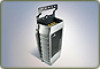
About RFID Readers RFID Readers: The left picture shows an IV7 vehicle-mount reader. The right picture shows an IP4 portable reader that is attached to a 700 mobile computer. Intermec's UHF readers are able to read and write to ISO 18000-6b and EPCglobal Gen 2 Class 2 tags. How Readers Affect RFID - Intermec IV7 | Intermec RFID System Manual - Page 46
reader from decoding the tag ID. Examples of these sources commonly found in the environment are: • other readers Electrical Noise and Interference Problems The best way to RFID system components, the source must be shielded with wire screen or other suitable material. 36 Intermec RFID System Manual - Intermec IV7 | Intermec RFID System Manual - Page 47
higher level of EMI (electromagnetic interference) shielding. How to Choose the Right Reader Intermec readers can be grouped into four categories based on the answer to these two questions: • Does the reader support more than one antenna? • Do you want the decision making (intelligence) performed - Intermec IV7 | Intermec RFID System Manual - Page 48
exception reading and subsequent rewriting of tag data. Smart readers combined with multiple antennas can cope with unpredictable tag placement, high tag volume through the reading range and high speed through the reading range. They can also provide local filtering. 38 Intermec RFID System Manual - Intermec IV7 | Intermec RFID System Manual - Page 49
explains the type of RFID antennas that you may use in your RFID system and how the antenna you choose affects the RFID system. This chapter covers these topics: • Understanding RFID antennas • How antennas affect the reading range • How to choose the right antennas Intermec RFID System Manual 39 - Intermec IV7 | Intermec RFID System Manual - Page 50
is considered the "active" region. Beyond the active region, the antenna radio signal is too weak to reliably maintain a communications link between the tag and reader. 40 Intermec RFID System Manual - Intermec IV7 | Intermec RFID System Manual - Page 51
Chapter 4 - Learning About RFID Antennas Understanding Antenna Radiation Patterns The antenna ratio of approximately 1.12. The antenna radiation pattern graphs apply only to the antenna's "far field." For Intermec antennas, the far field is considered to be a distance of 0.91 m (3 ft) or more from - Intermec IV7 | Intermec RFID System Manual - Page 52
Chapter 4 - Learning About RFID Antennas 310º 50º 340º 350º 330º 320º Attenuation dB 0º 10º 1 2 3 4 5 6 7 8 9 10 20º 30º 40º 300º 60º 290º 70º 280 directly above and below the antenna, respectively. The antenna signal is much weaker in these regions. 42 Intermec RFID System Manual - Intermec IV7 | Intermec RFID System Manual - Page 53
Chapter 4 - Learning About RFID Antennas 310º 50º 340º 350º 330º 320º Attenuation dB 0º 10º 1 2 3 4 5 6 7 8 9 10 20º 30º 40º 300º 60º 290º 70º 280º called "lobes" and "null regions." Their presence or absence is determined by the design of the antenna. Intermec RFID System Manual 43 - Intermec IV7 | Intermec RFID System Manual - Page 54
Chapter 4 - Learning About RFID Antennas 310º 50º 340º 350º 330º 320º Attenuation dB 0º 10º 1 2 3 4 5 6 7 8 9 10 20º 30º 40º 300º 60º 290º 70º 280 . Conductive materials, such as saltwater, attenuate the radio signal as it passes through the medium. 44 Intermec RFID System Manual - Intermec IV7 | Intermec RFID System Manual - Page 55
use them with discretion. You can also attenuate the field strength by changing the reader transmit power. Unlike an installed attenuator, this method does not affect the tag's return • Frequencies and bandwidth • Reading range performance • Environment • Cost Intermec RFID System Manual 45 - Intermec IV7 | Intermec RFID System Manual - Page 56
, and rail. For antenna integration support, contact: Kathrein Inc., Scala Division Attention: Dan Fowler P.O. Box 4580 Medford, OR 97501 U.S.A. Tel: 541-779-6500 Cell: 541-840-9889 Fax: 541-779-3991 e-mail: [email protected] web site: www.kathrein-scala.com 46 Intermec RFID System Manual - Intermec IV7 | Intermec RFID System Manual - Page 57
, to go-live support, service contracts and on-site preventative maintenance plans. This appendix provides checklists for designing and installing your Intermec RFID system. It outlines guidelines for: • designing your RFID system. • installing your RFID system. Intermec RFID System Manual 47 - Intermec IV7 | Intermec RFID System Manual - Page 58
shorter under special circumstances.) • Where uninterrupted service is critical, use an uninterruptible power supply and other interference. Some of the major causes of noise problems are: • excessive wiring inductance (ground, or shield). • Grounding • Filtering 48 Intermec RFID System Manual - Intermec IV7 | Intermec RFID System Manual - Page 59
Chapter 5 - Some Guidelines for Designing and Installing Your RFID System • Selection of RF frequencies The most common shielding problems involve: • coupling through apertures when D > λ/20, Radiative Electric motors connected to system power line Inductive Intermec RFID System Manual 49 - Intermec IV7 | Intermec RFID System Manual - Page 60
reader (generally). • Ground the communication equipment shield at either end, but not at both ends. A low noise grounding system can be established by employing the following techniques: • Isolate equipment racks from building steel • Use insulated equipment grounding conductors 50 Intermec RFID - Intermec IV7 | Intermec RFID System Manual - Page 61
Chapter 5 - Some Guidelines for Designing and Installing Your RFID System • Ensure only compatible equipment share a common grounding conductor Shielding Guidelines shields repeatedly. • Consider inductive coupling a more serious concern for low impedance circuits. Intermec RFID System Manual 51 - Intermec IV7 | Intermec RFID System Manual - Page 62
Chapter 5 - Some Guidelines for Designing and Installing Your RFID System 52 Intermec RFID System Manual - Intermec IV7 | Intermec RFID System Manual - Page 63
A Other Helpful Information Intermec RFID System Manual 53 - Intermec IV7 | Intermec RFID System Manual - Page 64
factors are often not constant, the r4 prediction must be used only as a guide to actual system performance. The following formulas assume that you know the tag's maximum calculated as follows: r = r′4 -P--P′ = 90feet″4 (---0---.-0---5----W------) 2W = 35.8 feet 54 Intermec RFID System Manual - Intermec IV7 | Intermec RFID System Manual - Page 65
modulated backscatter tags is determined primarily by the requirement to capture enough energy from the reader radio signal to power the tag. The inverse square law, which describes the density to field strength can be expressed by: Pd = --E----2-377 where: Intermec RFID System Manual 55 - Intermec IV7 | Intermec RFID System Manual - Page 66
of two is intentional so that 3 dB-whether it measures field strength or power density-always represents a factor of two change in power density. 56 Intermec RFID System Manual - Intermec IV7 | Intermec RFID System Manual - Page 67
Chapter A - Other Helpful Information How Readers Decode the Radio Signal Binary characters recognized by the RFID system are made up of sets of ones and zeros (bits) arranged Two-bit long frame marker 40kHz Cycles 20kHz Cycles Frequency-Shift Keying (FSK) Encoding Intermec RFID System Manual 57 - Intermec IV7 | Intermec RFID System Manual - Page 68
Appendix A - Other Helpful Information Because the tag data is contained solely in the modulating frequencies, the polarity of the signal is of no consequence. 58 Intermec RFID System Manual - Intermec IV7 | Intermec RFID System Manual - Page 69
I Index Intermec RFID System Manual 59 - Intermec IV7 | Intermec RFID System Manual - Page 70
, 15 See also reading range. channels primary service, 8 secondary service, 8 code frame, reading, 16, 30 RFID system, 15 reader vulnerability, 35 removing, 36 sources, 36 electronic ID systems, defined, 2 environmental capabilities, RFID systems, 18, 20 EPCglobal standards, 4 Intermec supported - Intermec IV7 | Intermec RFID System Manual - Page 71
capabilities, 20 Intermec RFID System Manual Index frequency and power, supported, 20 operational characteristics, 19 radio signals, 20 reading range, 20 supported, 19 service and support, vii telephone support, viii warranty information, vii web support, vii interrogator, See reader. inverse - Intermec IV7 | Intermec RFID System Manual - Page 72
reader influences, 35 pitch, antennas and tags definition, 29 illustrated, 29 placement, antennas and tags, 17, 28 polarization, See tag orientation. power density, 11 and the radio signal, 10 definition, 10 levels supported by Intermec factors, 15 tag influences, 27 62 Intermec RFID System Manual - Intermec IV7 | Intermec RFID System Manual - Page 73
, 29 illustrated, 29 rusty joint problems, 17 S safety information, vii semi-passive tag, See active backscatter tags. service and support, Intermec, vii shielding, guidelines, 51 signals, See radio signals. simple scanners, when to use, 38 smart labels, See tag. smart readers, when to use, 38 - Intermec IV7 | Intermec RFID System Manual - Page 74
-high frequency systems, 7 modulated backscatter, 31 understanding, 22 WORM, understanding, 23 telephone support, Intermec, viii transponders, See tag. troubleshooting, rusty joint problems, 17 U-V UHF systems, 6, 19 reading range, 7 regulatory agency guidelines, 7 tags, 7 understanding, 7 ultra - Intermec IV7 | Intermec RFID System Manual - Page 75
- Intermec IV7 | Intermec RFID System Manual - Page 76
Corporate Headquarters 6001 36th Avenue West Everett, Washington 98203 U.S.A. tel 425.348.2600 fax 425.355.9551 www.intermec.com Intermec RFID System Manual *936-000-001* P/N 936-000-001
-
 1
1 -
 2
2 -
 3
3 -
 4
4 -
 5
5 -
 6
6 -
 7
7 -
8
-
9
-
10
-
11
-
12
-
13
-
14
-
15
-
16
-
17
-
18
-
19
-
20
-
21
-
22
-
23
-
24
-
25
-
26
-
27
-
28
-
29
-
30
-
31
-
32
-
33
-
34
-
35
-
36
-
37
-
38
-
39
-
40
-
41
-
42
-
43
-
44
-
45
-
46
-
47
-
48
-
49
-
50
-
51
-
52
-
53
-
54
-
55
-
56
-
57
-
58
-
59
-
60
-
61
-
62
-
63
-
64
-
65
-
66
-
67
-
68
-
69
-
70
-
71
-
72
-
73
-
74
-
75
-
76
 |
 |

Intermec RFID
System Manual