KitchenAid KCMS2255BSS Installation Guide
KitchenAid KCMS2255BSS Manual
 |
View all KitchenAid KCMS2255BSS manuals
Add to My Manuals
Save this manual to your list of manuals |
KitchenAid KCMS2255BSS manual content summary:
- KitchenAid KCMS2255BSS | Installation Guide - Page 1
9 Install the Microwave Oven 9 Complete Installation 10 VENTING DESIGN SPECIFICATIONS 11 ASSISTANCE 12 Replacement Parts 12 Accessories 12 MICROWAVE HOOD COMBINATION SAFETY Your safety and the safety of others are very important. We have provided many important safety messages in this manual - KitchenAid KCMS2255BSS | Installation Guide - Page 2
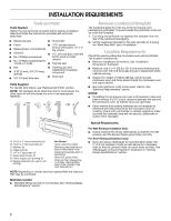
(attached to back of microwave oven) Cardboard template (part of packaging) Aluminum grease filters Charcoal filters (Depending on model, charcoal filters may not be included. See User Instructions.) NOTE: Depending on model, aluminum grease filter and charcoal filter may be combined. Materials - KitchenAid KCMS2255BSS | Installation Guide - Page 3
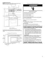
for 66" (167.6 cm) installation height. Exact dimensions may vary depending on type of range/cooktop below. Product Dimensions 17¹⁄₄" (43.8 cm) 16¹⁄₄" (41.3 cm) (401.05³c⁄₄m") 29⁷⁄₈" (76.0 cm) GROUNDING INSTRUCTIONS ■ For all cord connected appliances: The microwave oven must be grounded. In - KitchenAid KCMS2255BSS | Installation Guide - Page 4
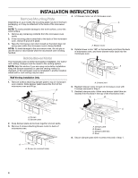
INSTALLATION INSTRUCTIONS Remove Mounting Plate Depending on your model, the mounting plate may be in the foam packaging, or it may be attached to the back of the microwave oven. NOTE: To avoid possible damage to the work surface, cover the work surface. 1. Remove any remaining contents from the - KitchenAid KCMS2255BSS | Installation Guide - Page 5
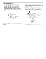
ports face the top of microwave oven, and flat sides of blower motor face back of microwave oven. Lower blower motor back into microwave oven. A 6. Reattach blower motor to back of microwave oven with 2 screws removed in Step 3 of "Wall Venting Installation Only." Securely tighten screws. NOTE - KitchenAid KCMS2255BSS | Installation Guide - Page 6
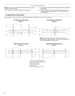
wall studs exist within the cabinet opening, do not install the microwave oven. 1. Using a stud finder, locate the edges of A. End holes (on mounting plate) B. Cabinet opening vertical centerline C. Wall stud centerlines D. Holes for lag screws E. Support tabs F. Mounting plate center markers 6 - KitchenAid KCMS2255BSS | Installation Guide - Page 7
microwave oven must be installed unusable, measure and mark the wall with the dimensions described in Step 4. D A C B ) from the centerline. 5. With the support tabs facing forward (see illustrations in " hole locations. 7. Set the mounting plate aside. Wall Venting Installation Only Upper cabinet - KitchenAid KCMS2255BSS | Installation Guide - Page 8
as well as at both ends. 1. With the support tabs of the mounting plate facing forward, insert 1/4- trim lines to use as guides. ■ If the wall behind the microwave oven (as installed) has a partial wall covering (for example, tile backsplash), be sure the "Rear Wall" arrows align to the thickest part - KitchenAid KCMS2255BSS | Installation Guide - Page 9
, lift microwave oven and hang it on support tabs at the bottom of mounting plate. NOTE: To avoid damage to the microwave oven, do not grip or use the door or door handle while the microwave oven is being handled. A. Back of microwave oven B. Damper assembly C. Damper blade D. Sheet metal screws - KitchenAid KCMS2255BSS | Installation Guide - Page 10
a cook time of 1 minute at 100% power. Test vent fan and exhaust by operating the vent fan. 5. If the microwave oven does not operate: ■ Check that a household fuse has not blown, or that a circuit breaker has not tripped. Replace the fuse or reset the circuit breaker. If the problem continues - KitchenAid KCMS2255BSS | Installation Guide - Page 11
VENTING DESIGN SPECIFICATIONS This section is intended for architectural designer and builder/contractor reference only. NOTES: ■ Vent materials needed for installation are not provided with microwave hood combination. ■ We do not recommend using a flexible metal vent. ■ To avoid possible product - KitchenAid KCMS2255BSS | Installation Guide - Page 12
Replacement Parts If any of the installation hardware needs to be replaced, call us at our toll free number listed in the User Instructions. Following is a list of available replacement parts. You will need your model number located on the front facing of the microwave oven opening, behind the door
-
 1
1 -
 2
2 -
 3
3 -
 4
4 -
 5
5 -
 6
6 -
 7
7 -
8
-
9
-
10
-
11
-
12
 |
 |
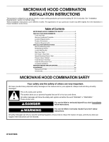
MICROWAVE HOOD COMBINATION
INSTALLATION INSTRUCTIONS
MICROWAVE HOOD COMBINATION SAFETY
This product is suitable for use above electric or gas cooking products up to and including 36" (91.4 cm) wide. See “Installation
Requirements” section for further notes.
These installation instructions cover different models. The appearance of your particular model may differ slightly from the illustration in
these installation instructions.
Table of Contents
MICROWAVE HOOD COMBINATION SAFETY
..............................
1
INSTALLATION REQUIREMENTS
...................................................
2
Tools and Parts
...............................................................................
2
Remove Cardboard Template
........................................................
2
Location Requirements
...................................................................
2
Product Dimensions
.......................................................................
3
Electrical Requirements
..................................................................
3
INSTALLATION INSTRUCTIONS
.....................................................
4
Remove Mounting Plate
.................................................................
4
Rotate Blower Motor
.......................................................................
4
Locate Wall Stud(s)
.........................................................................
6
Mark Rear Wall
................................................................................
7
Drill Holes in Rear Wall
....................................................................
7
Attach Mounting Plate to Wall
........................................................
8
Prepare Upper Cabinet
...................................................................
8
Install Damper Assembly
................................................................
9
Install the Microwave Oven
............................................................
9
Complete Installation
....................................................................
10
VENTING DESIGN SPECIFICATIONS
............................................
11
ASSISTANCE
...................................................................................
12
Replacement Parts
.......................................................................
12
Accessories
...................................................................................
12
W10247296B
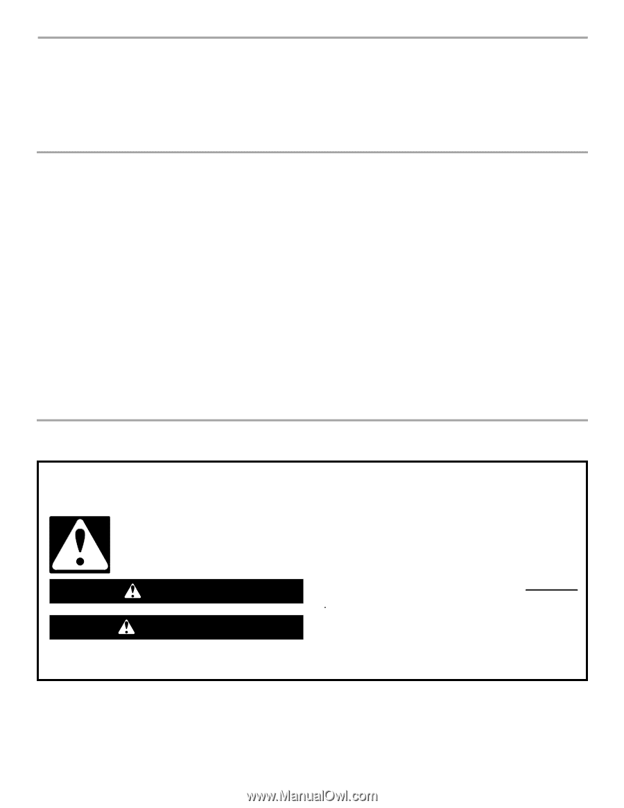
You can be killed or seriously injured if you don't immediately
You
can be killed or seriously injured if you don't follow
All safety messages will tell you what the potential hazard is, tell you how to reduce the chance of injury, and tell you what can
happen if the instructions are not followed.
Your safety and the safety of others are very important.
We have provided many important safety messages in this manual and on your appliance. Always read and obey all safety
messages.
This is the safety alert symbol.
This symbol alerts you to potential hazards that can kill or hurt you and others.
All safety messages will follow the safety alert symbol and either the word “DANGER” or “WARNING.”
These words mean:
follow instructions.
instructions.
DANGER
WARNING